10
32HW-53E
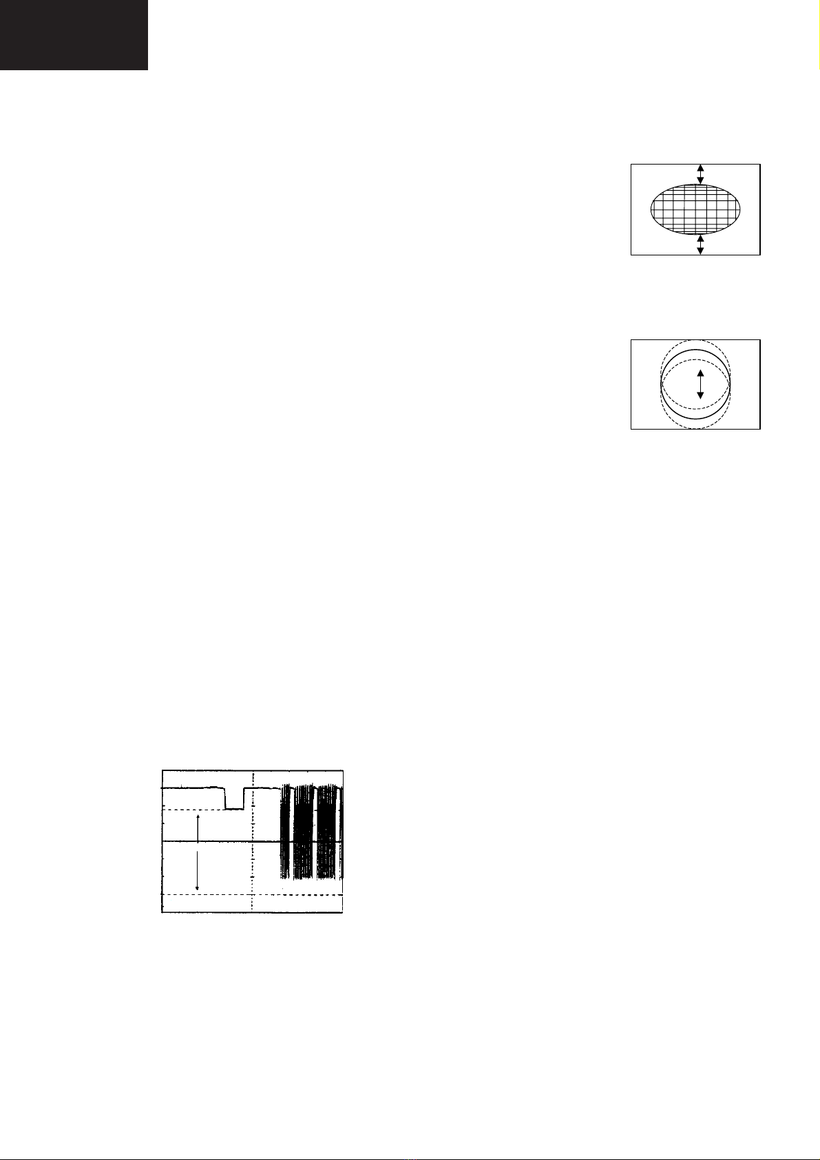
DVCO Adjustment (PAL)
Carry out the DVCO Adjustment (PAL) as shown below:
1. Receive a Phillips pattern signal.
2. While in the DVCO ADJUSTMENT (PAL) menu, press
the standby button.
3. The adjustment will be carried out automatically and
stored.
DVCO Adjustment (NTSC)
No adjustment required.
Auto Installation On/Off
To return the receiver to the original Auto Installation mode,
using the volume up or down button, set the Auto Installa-
tion On/Off to On. This setting is automatically stored and
when the receiver is turned on the next time it will start up in
Auto Installation mode.
AGC Adjustment
To correctly align the Automatic Gain Control, follow the
procedure outlined below:
1. Tune the set into a pattern generator on CH10.
2. Adjust the signal strength of the pattern generator to 57uV
3. Enter the service mode.
4. Enter the AGC Adjustment menu.
5. Press the standby button on the remote control.
6. The adjustment will be carried out and stored
automatically.
AFT Adjustment (BG-I, SECAM L)
To correctly align the Automatic Fine Tune, follow the
procedure outlined below:
1. Tune the set into a pattern generator on CH69.
2. Enter the service mode.
3. Enter the AFT Adjustment menu.
4. Press the standby button on the remote control.
5. The adjustment will be carried out and stored
automatically.
AFT Adjustment (SECAM L’)
To correctly align the Automatic Fine Tune, follow the
procedure outlined below:
1. Tune the set into a pattern generator on F04.
2. Enter the service mode.
3. Enter the AFT Adjustment menu.
4. Press the standby button on the remote control.
5. The adjustment will be carried out and stored
automatically.
LED FLASHING CODES
This model is not provided with stereo led, so to let “flashing
codes” for IC failures detection when the TV set does not
work, we have answered with the next solution:
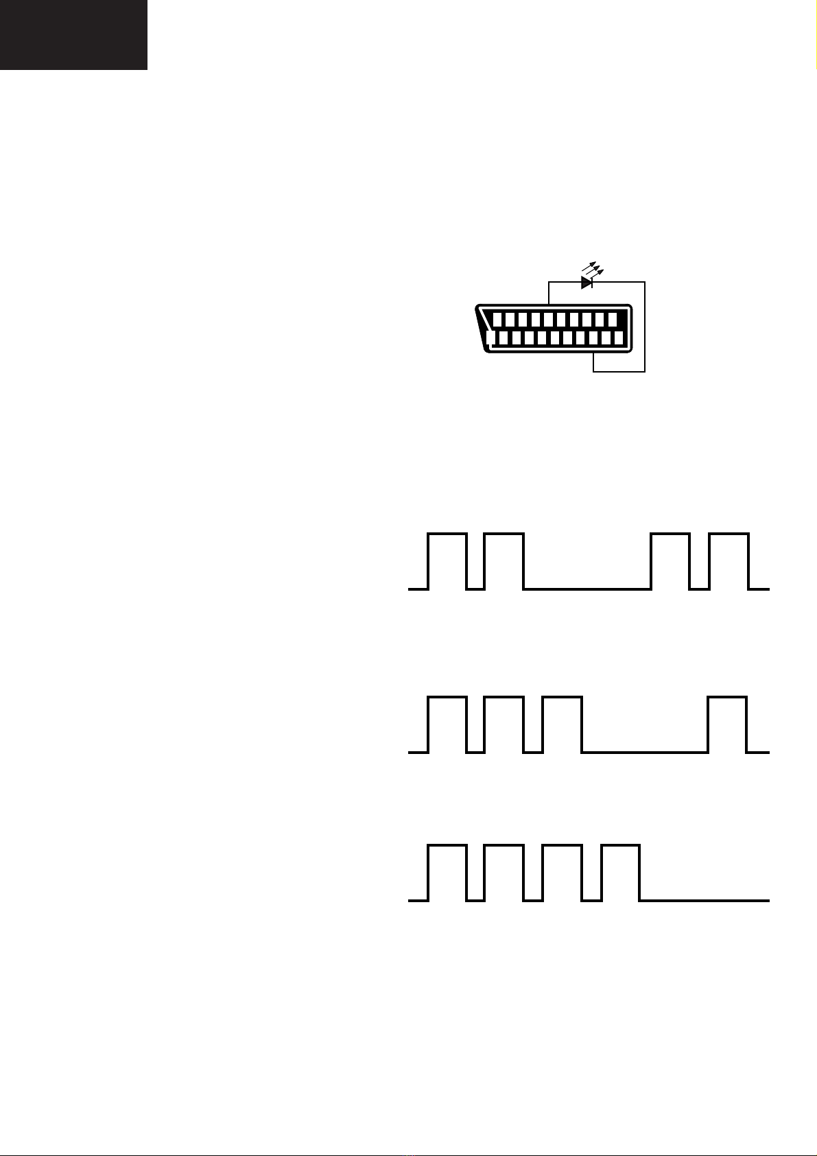
• The detection of failure will be made with an external LED.
• The output of the flashing code will be via AV1 (pin 12).
• Insert a generic led diode between pin 12 and ground (i.e.
pin 5, 13 or 21) as shows the below picture.
Follow the sequence according to the information below, as
a guide to fault finding.
1. Unable to read or write into NVM: 66% ON, 33% OFF
twice and OFF for a second.
2. MSP failure: 66% ON, 33% OFF for three times and
OFF for a second.
3. VDP failure: 66% ON, 33% OFF for four times and OFF
for a second.
NOTE:
If you want to check that the system is working, open resis-
tor R307 to avoid I2C comunication with MSP. The TV set
will flash three times and OFF for a second, showing MSP
failure.
Then the system is working properly.
On Off
On Off
On Off
21
21 19 17 15 13 11 9 7 5 3 1
20 1 16 14 12 10 6 4 2