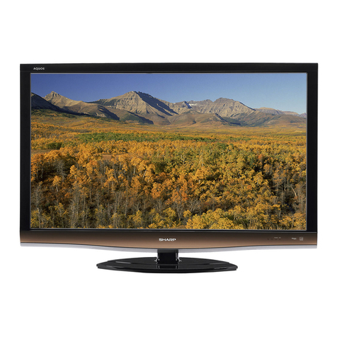
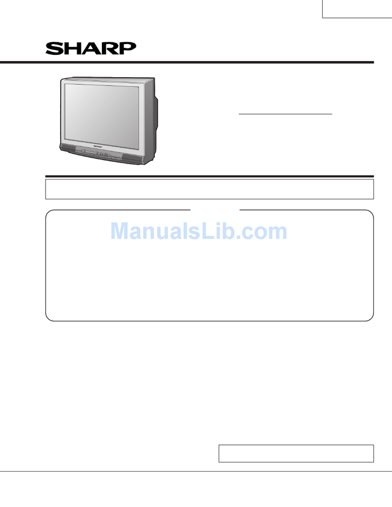
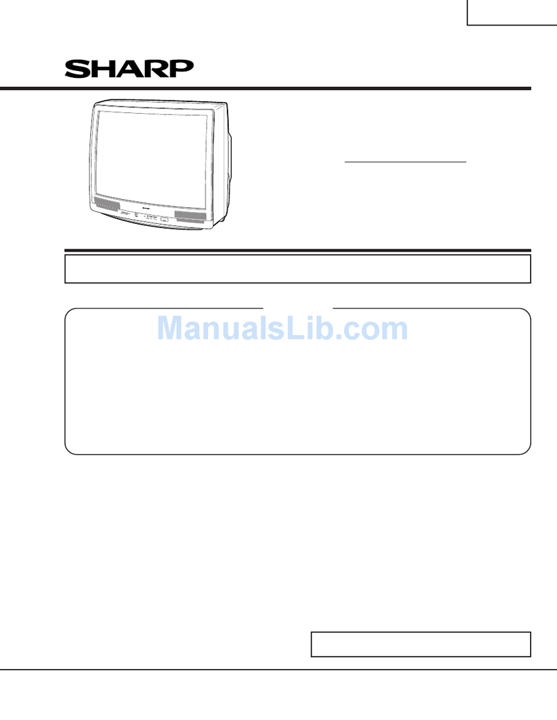
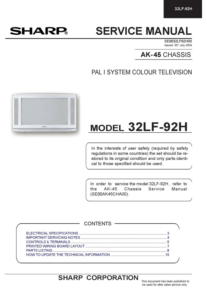
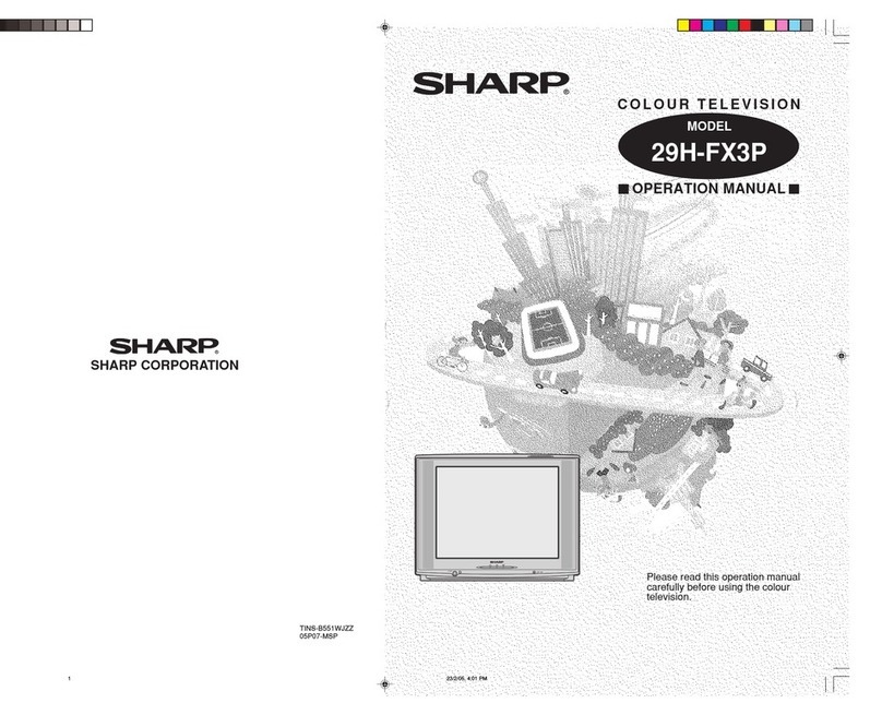
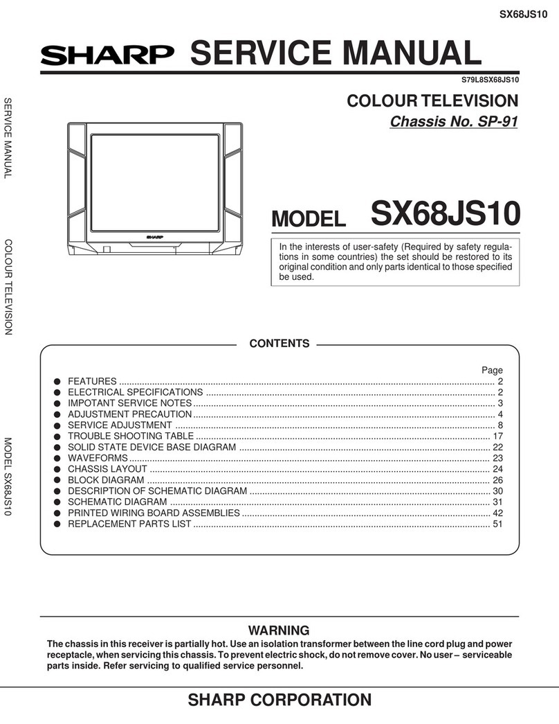
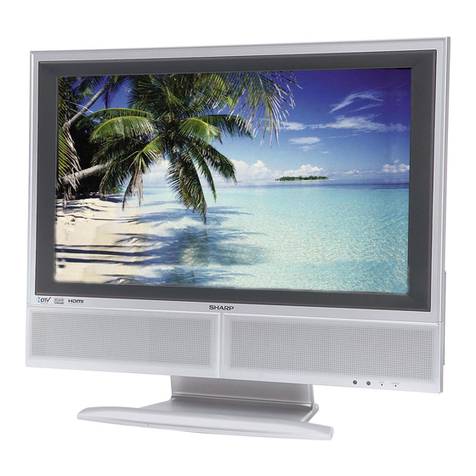
Sharp LC-26D44 Installation guide

Training course: D44
1
SEES Engineering Department
Presentation By:
Jan Niemi
Issued: Sofía García
SEES Engineering Department
MODELS:
LC-26D44
LC-32D44
Training Course
May 2008

Training course: D44
2
SEES Engineering Department
1. Models introduction
2. Block Diagram
3. Software Updating
4. Service Mode
5. LCD Adjust Process
6. Electrical Diagrams / PWB
Index

Training course: D44
3
SEES Engineering Department
1. Models Introduction
Sizes:
26” & 32”
Type of cabinet:
- Bottom speakers.
- BK : Black Color.
- GY: Grey Color.
Models:
LC-26/32D44EE-BK/GY → Continental
LC-26/32D44ES-BK/GY → Sweden Market
LC-26/32D44EK-BK/GY → United Kingdom
LC-26/32D44RU-BK/GY → Russian Market

Training course: D44
4
SEES Engineering Department
1. Models Introduction (continued)
• ASV & Black TFT LCD.
• HD Ready Panel (1366 x 768) WXGA with 4ms response.
• Wide vision angle (H/V 176º).
• High brightness and contrast (1.500:1).
• Interlaced and progressive mode compatible (I/P).
• Built-in DVB-T Tuner.
• Multistandard Video and audio:
- Multistandard Video & audio .
- Video: PAL/SECAM & NTSC (AV only).
- TV: B/G, I, D/K, L & L’.
- Sound: NICAM & A2 (IGR).
• OSD multilanguage.
• 2 HDMI 1.2 inputs (Video Digital, Audio Digital
& Analog).
• Analog mode PC input.
• Components Input ( 3RCA to 15pin D-sub adapter).
• RGB at EXT1/EXT2 Terminal.
• RS-232C.
• AV-Link at EXT2.
• Does not support CEC at HDMI.
• Active Backlight (dynamic contrast 10.000:1)
• Sleep Timer.
• Does not support “RC Path Through” by Pin Nº 9 of
Service Connector.
LC-26D44 & LC-32D44 Models
Specifications
Item 26oLCD COLOUR TV, Model: LC-26D44E, LC-26D44S
LCD panel 26oAdvanced Super View & BLACK TFT LCD
Resolution 1,049,088 pixels (1,366 g768)
Video Colour System PAL/SECAM/NTSC 3.58/NTSC 4.43/PAL 60
TV
Function
TV-Standard Analogue CCIR (B/G, I, D/K, L, L’)
Digital DVB-T (2K/8K OFDM)
Receiving
Channel
VHF/UHF E2–E69ch, F2–F10ch, I21–I69ch, IR A–IR Jch, (Digital: E5–E69ch)
CATV Hyper-band, S1–S41ch
TV-Tuning System Auto Preset 99 ch, Auto Label, Auto Sort
STEREO/BILINGUAL NICAM/A2
Brightness 450 cd/m2
Backlight life 60,000 hours (at Backlight Standard position)
Viewing angles H : 176° V : 176°
Audio amplifier 10W g2
Speaker Ø XX mm g2, Ø XX mm g2
Terminals Antenna UHF/VHF 75qDin type (Analogue & Digital)
RS-232C 9 pin mini D-sub
EXT 1 SCART (AV input, Y/C input, RGB input, TV output)
EXT 2 SCART (AV input/output, Y/C input, RGB input, AV Link)
EXT 3 S-VIDEO (Y/C input), RCA pin (AV input)
EXT 4 Ø 3.5 mm jack (Audio input), 15 pin mini D-sub (PC)
EXT 5 Audio in, Component in
EXT 6 HDMI, Ø 3.5 mm jack (Audio input)
EXT 7 HDMI
C. I. (Common Interface) EN50221, R206001
OUTPUT RCA pin (Audio)
Headphones Ø 3.5 mm jack (Audio output)
OSD language English/German/French/Italian/Spanish/Dutch/Swedish/Portuguese/Finnish/Turkish/Greek/
Russian/Polish
Power Requirement AC 220–240 V, 50 Hz
Power Consumption XXX W (0.9 W Standby) (Method IEC60107)
Weight XX.X kg (Display only), XX.X kg (Display with stand)
Operating temperature 0°C to k40°C
• As a part of policy of continuous improvement, SHARP reserves the right to make design and specification changes for
product improvement without prior notice. The performance specification figures indicated are nominal values of production
units. There may be some deviations from these values in individual units.
TV LCD 26”: LC-26D44E/S/K/RU TV LCD 32”: LC-32D44E/S/K/RU
120W (0,9 Standby) Method IEC60107)
10,5 Kg (With Stand) 13,0 Kg (With Stand)
95W (0,9 Standby) Method IEC60107)

Training course: D44
7
SEES Engineering Department
2. Block Diagrams
Main ICs
IC207: COFDM DECODER (Coded Orthogonal Frequency Division Multiplexing)
Part Number : STV0362 SHARP Code: RH-IXB964WJZZQ
The STv0362 is a single-chip demodulator using COFDM and is intended for digital terrestrial receivers using compressed video, sound and data
services. It converts IF or base band differential signals to MPEG-2 transport stream format by processing OFDM carriers. The STv0362 is fully
compliant with the DVB-T specification (ETS 300 744) and Nor Dig Unified specification.
IC1951: HDMI RECEIVER (High Definition Multimedia Interface)
Part number : Sii9025 SHARP Code : VHISII9025+-1Q
The Sii9025 is a compliant with the latest HDMI 1.2 (High Definition Multimedia Interface) specification. Backward compatibility with DVI 1.0 allows
HDMI systems to connect to existing DVI 1.0 hosts. The SiI9025 is capable of receiving and outputting two channel digital audio at up to 192 kHz-
an excellent solution for Digital TVs. An S/PDIF port supports up to 192 kHz audio. The SiI9025 also comes pre-programmed with HDCP keys,
greatly simplifying the manufacturing process, while providing the highest level of HDCP key security.
This IC includes the main features show below:
1- Dual-Input HDMI 1.2, HDCP 1.1 and DVI 1.0 compliant receiver.
2- Integrated TMDSR core.
3- Digital video interface supports video processors:
• 24-bit RGB/YCbCr 4:4:4
• 16/20/24-bit YCbCr 4:2:2
• 8/10/12-bit YCbCr 4:2:2 (ITU BT.656)
• 12-bit DMO (Digital Multimedia Output) RGB/YCbCr 4:4:4 (clocked with rising & falling edges)
• Color Space Conversion for both RGB-to-YCbCr and YCbCr-to-RGB (both 601 and 709)
• Auto video mode configuration simplifies system firmware design

Training course: D44
8
SEES Engineering Department
2. Block Diagrams (continued)
Main ICs
4- Digital audio interface supports high-end audio systems:
• One programmable I2S output for connection to low-cost DACs at 32-192kHz.
• S/PDIF output supports PCM, Dolby Digital, DTS digital audio transmission (32-192 kHz Fs) using IEC60958 and IEC61937.
• Auto audio error detection with programmable soft mute.
5- Integrated HDCP decryption engine for receiving protected audio and video content.
6- HDCP Built in Self Test (BIST) lowers cost to test HDCP operation.
7- Pre-programmed HDCP keys provide highest level of key security, simplifies manufacturing.
IC1922 & IC1902: NVM OF HDMI (E-EDID)
Part Number : 24LC2BIN SHARP Code: VHI24LC2BIN-1Y
This IC is a 2-wire (I2C bus type) serial EEPROM this is electrically programmable. This EEPROM chip stores the data structure used to carry
configuration information for optimal use of a display (EDID data).
IC4001: DIGITAL PROCESSOR MPEG 1/2 DECODER (Audio/Video)
Part Number : STI5105ALC SHARP Code: RH-IXC243WJZZQ
The STi5105ALC sets a new standard for set-top box decoder ICs, delivering outstanding performance, features and innovations to dramatically
reduce cost compared with previous generations. The Sti5105 features an even faster ST20CPU with direct map, single cycle caches to boost
performance.
Graphics and display capabilities have been enhanced with the provision of a blitter engine for formatting and final display composition. Color
formats (CLUT8 and true color ARGB16) and display planes (background, still picture, video and OSD graphics) are provided. Overall system
performance benefits from the integration of SDRAM (DDR or SDR) external memory, that provides a unified memory system with high bandwith
and low latency CPU access over a 16-bit interface.
System cost reduction is further promoted by the integration of additional peripheral and system services functions, such as VCXO, an enhancer
reset controller, DVB-CI support, smartcard power control and improved low power and standby functionality.

Training course: D44
9
SEES Engineering Department
2. Block Diagrams (continued)
Main ICs
This IC includes the main features show below:
1- An enhanced ST20 32-bit VL-RISC CPU with a 200MHz clock, 4Kbytes of instruction cache, 4Kbytes of data cache and 2Kbytes of
embedded SRAM.
2- A 16-bit, 166MHz Shared Memory Interface, with support for 64- and 128-bit configurations.
3- A programmable External Memory Interface supporting 4 separately configurable banks of SRAM, Flash and DRAM.
4- An MPEG-2 (MP@ML) decoder, including trick modes such as smooth fast-forward and rewind.
5- A Graphics/Display unit with 4 display planes, alpha blending, antialiasing and antiflutter filters, subpicture decoder, and blitter
display compositor with separate OSD (On-Screen Display) controls for TV and VCR outputs.
6- PAL/NTSC/SECAM encoder.
7- CGMS, Teletext, WSS, VPS encoder.
8- MPEG-1 layer I/II audio subsystem with embedded DSP for all popular audio formats.
9- A full range of on-chip peripherals, including 2 UARTs, 3 parallel I/O banks, 1 smartcard interface, four PWM channels, 1 IR
transmitter/receiver, etc.
IC4252: NVM 64Kb-E2PROM FOR DIGITAL PROCESSOR (IC4001).
Part Number : BR24S64FVM-WTR SHARP Code: VHIBR24S64M-1Y
The BR24S64FVM is a 2-wire (I2C bus type) serial EEPROM that is electrically programmable. This IC stores all data related to the Digital Module
(Channels, User settings, etc.).

Training course: D44
10
SEES Engineering Department
IC3001: Main CPU / VIDEO PROCESSOR.
Part Number: VCT7993P-FA-A1-H000 SHARP Code: RH-IXC354WJZZQ
The VCT 77VWP (VCT-Pro) family is dedicated to high-quality FPD and double-scan TV sets. The memory and program ROM are integrated in
the IC. Modular design and deep submicron technology allow the integration of audio, video, Teletext, OSD, and controller-related functionalities.
They cover the whole range of flat-panel display TVs. Each member of the IC family contains the entire audio, video, up-conversion processing for
4:3 and 16:9 50/60 Hz progressive or 100/120 Hz interlaced stereo TV sets plus the control/data interface for flat-panel displays. The integrated
microcontroller supports a powerful OSD and graphics generator with integrated Teletext acquisition.
The VCT 77vwP family provides a front-end video-processing unit with 4 CVBS-Y/C or component inputs for HDTV, EDTV and SDTV. A VBI slicer,
support of 2000 pages of Teletext, and a 3-D comb filter for PAL and NTSC (in certain versions) are also available. The front-end unit further allows
processing an SD and an HD source in parallel, thus enabling PiP and PaP functionality. Motion-adaptive de-interlacing, temporal noise reduction,
and film mode detection are based on a unified memory technology. Post-scaling in the display-processing block ensures the desired output format.
Display processing is supported by an 8-bit 8051-compatible controller. By means of powerful alpha blending, the graphics mixer composes the
output image from following image layers: the video layer, the OSD layer and the pixel graphics layer. The audio part consists of a multi-standard
sound IF demodulator and a base-band processor supporting all desired sound features in this range.
The VCT-Pro front-end video processing unit offers 16 analog video inputs (CVBS/Y/C, RGB/Y Cr Cb) as well as digital interfaces for SDTV and
HDTV. Latest 3D+ comb filter generation provides highest performance for PAL/NTSC signals.
A VBI slicer, supporting up to 2000 pages of Teletext completes the analog video front end. 3D-motion-adaptive de-interlacing, temporal noise re-
duction and film mode detection are based on a unified memory technology.
2. Block Diagrams (continued)
Main ICs

Training course: D44
11
SEES Engineering Department
This IC includes the main features show below:
1- Stereo Decoder Audio Processing.
2- Video Front-end 3D Comb filter, PC Connectivity.
3- Motion Adaptive Deinterlacer.
4- Scaling, Display Processing and FPD Control.
5- Unified Memory for Audio, Video and Teletext.
6- OSD and Teletext processor.
7- Main CPU (TV controller).
IC3051: NVM 64Kb-E2PROM FOR ANALOG PROCESSOR (IC3001).
Part Number: BR24S64FVM-WTR SHARP Code: VHIBR24S64M-1Y
The BR24S64FVM is a 2-wire (I2C bus type) serial EEPROM that is electrically programmable. This IC stores all data related to the Analog Module
(Channels, User settings, etc.)
IC2302: SUB-CPU AND PORT EXPANSOR.
Part Number: TMP86FS49AUG-6NU2 SHARP Code: RH-IXC009WJZZQ
This IC functions as ports Expansor of the main microcontroller (e.g leds, remote control, key, Power Supply supervisor, Audio mutes, LCD control-
ler signals, temperature sensor, lamp error, etc..).
This microcontroller integrates 60KB of Flash memory, 2KB of RAM. It’s including 56 I/O pins (13 high current) with 2 UARTS, 1 I2C serial link, 16
channels of 10 bits A/D converters, 2 timers 16 bits.
2. Block Diagrams (continued)
Main ICs

Training course: D44
12
SEES Engineering Department
2. Block Diagrams (continued)
Main ICs
IC1301: DIGITAL AUDIO POWER AMPLIFIER
Part Number: YDA147-SZE2 SHARP Code: VHIYDA147SZ-1Y
This IC is a Stereo 20W (10W+10W) digital audio power amplifier. The IC is class D amplifier equipped with the function for the dynamic self-adjust-
ment of the output volume in proportion to the amplitude of the input signal. The company calls the function of automatic adjustment of the installed
output volume “DRC (dynamic range compression)”.
The modulation method adopted PWM. An external LC filter is unnecessary. It only has to supply the output signal directly to the speaker. It has the
output control function to prevent an excessive input to the speaker. The maximum output electric power can be set to an arbitrary size by external
resistance. Besides this, the protection function to overheating and the overcurrent was installed.
The switching operation of power MOS-FET is installed and the technology that carefully controls the slewing rate is installed. Moreover, the auto-
matic offset calibration circuit that suppresses the pop noise when the power supply starts is built into.
IC8103: LCD CONTROLLER
Part Number: T3Z18AFG-0003 SHARP Code: VHIT3Z18AFG-1Q
This IC is a custom Gate Array of Toshiba. The alias of this IC is EAGLE2 and is marked as SHARP. This IC is generating all the necessary timing
signals for controlling the panel and the RSDS interface for data..
IC8101: NVM 256Kb -E2PROM FOR LCD CONTROLLER (IC8103)
Part Number: M24256-BWMN6TP SHARP Code: VHIM24256B +-1L
The BR24256B is a 2-wire (I2C bus type) serial EEPROM that is electrically programmable. This IC stores all data related to the LCD Controller
(Gamma, timings, etc…).

Training course: D44
13
SEES Engineering Department
2. Block Diagrams (continued)
Main ICs
IC203: I2C BUS SELECTOR
Part Number: SN74LV4053APWR SHARP Code: VHILV4053AT-1Y
The SN74LV4053APWR is a high-speed CMOS analog multiplexer/demultiplexer backed by silicon gate CMOS technology. The multiplexer func-
tion includes the selection and mixing of analog and digital signals. The chip includes two independent 3 channels selectors. A digital signal through
the control terminal turns on the switch of a corresponding channel. This IC is selecting if the Tuner is controlled from VCT-Pro (ATV mode) or from
OFDM decoder (DTV mode).
IC1201: NVM OF PC INPUT (EDID)
Part Number: BRC21F SHARP Code:VHIBR24C21F-1Y
This IC is a 2-wire (I2C bus type) serial EEPROM this is electrically programmable. This EEPROM chip stores the data structure used to carry
configuration information for optimal use of a display (EDID data).
IC1501: RS-232 TRANSCEPTOR
Part Number: ISL83220 SHARP Code: VHIISL83220-1Y
This ISL83220 is a 3.0V to 5.5V powered RS-232 transceiver (emitter/receiver), +/-15kV ESD protected, with a maximum data rate of 250 kbps.

Training course: D44
18
SEES Engineering Department
2. Block Diagrams (continued)
Overall Wiring Diagram 26”

Training course: D44
20
SEES Engineering Department
EMI Filter + Rectifier
PFC
BUCK CAP.
L7103 & Q7305
AC Brown out
VCC
C7108
Primary Secondary
Power Block
Signal Block
High Voltage
path
High Current path
Signal path
Comments
Comments
5V O/P rectifier
Controller
U7101
BU5V* 1A
5V Feedback Loop
U7102
PS_ON
System Interface
S13V*2A
13V*0.5A
DCM controller
U7300
AC-DETECT
13V O/P rectifier
ON/OFF switch
FLYBACK
T7101
AC Input
ޓ
220~240Vac
38V O/P rectifier
1
ψ
2 Transformer
1
ψ
2 Transformer
1
ψ
2 Transformer
1
ψ
2 Transformer
1
ψ
2 Transformer
Controller
IC7500
Dimming Control,
Other I/O signal
CCFL
10lamps
8.5mA
1700V Typ.
33.9KHz Typ.
FULL
Bridge
MOS7500
MOS7502
MOS7501
MOS7503
Feedback,
Protections
AC_DET
STB, OFL1,OSC,
REG,REG2,BRT,ADIM
ERR
+
+
+
+
+
-
-
-
-
-
ON/OFF Feedback Loop
U7203
Q7291
Q7265
38V*1.8A
Lamp Open & Shorted
OFL=150Hz
20% min
RUNTKA395WJQZ Power Supply & Inverter Block Diagram (26”)

Training course: D44
21
SEES Engineering Department
2. Block Diagrams (continued)
RUNTKA396WJQZ Power Supply Block Diagram (32”)
HALF
BRIDGE
Nº 1
CURRENT
SENSOR
Nº2
REG
PS_ON
AC DET PS_ON 60/13V OVERVOLTAGE
BU+5V REG
13V OVERVOLT.
60V OVERVOLT.
60/13V REG
13V SHORT DET
STBY ON/UNDERV.

Training course: D44
22
SEES Engineering Department
2. Block Diagrams (continued)
RUNTKA396WJQZ Inverter Block Diagram (32”)
HIGH CURRENT LAMP
LOW VOLT LAMP
LAMP OPEN
SHORT CIRCUIT PROTECTION
TIMER LATCH
C7558=GROUND PROT DISABLED

Training course: D44
23
SEES Engineering Department
3. Software Updating
HOW TO UPDATE THE SOFTWARE
VCTPro SOFTWARE UPDATE
There are 4 methods to update software in the VCTpro:
• RS-232C HyperTerminal Method
• RS-232C Tera Term Method
NOTE: (RS-232C method is allowed when the TV is working properly and the action should be only software upgrade)
• I2C Method
• PCMCIA Card Method (NEW!!)
DIGITAL SOFTWARE UPDATE
There are 2 methods to update the Digital Board Software on Flash Memory (IC4203) throught the Digital Processor
(IC4001):
• PCMCIA CARD (Compact Flash Memory) Method
NOTE: The PCMCIA method is only compatible with those PCs running XP Windows Version.
• Jig RS-232 WinUpload Method (From PC through RS-232C COM port)

Training course: D44
55
SEES Engineering Department
4. Service Mode
HOW TO ENTER TO SERVICE MODE
Press the “POWER” key on the set of running TV set to force off the power.
While holding down the “VOL (-)” and “INPUT” keys on the set at once, plug in the AC power cord to turn on the power.
The letter “K”, appears on the screen.
Next, hold down the “VOL (-)” and “P (-)” keys on the set at once. Multiple lines of character string appearing on the
screen indicate that the set is now in the adjustment Process mode. If you fail to enter the adjustment mode (the display
is the same as normal start-up), retry the procedure. (Another procedure)
To exit of Service Mode, after the adjustment is done, unplug the AC power cord to force off the power. (When the
power is turned off with the remote controller, once unplug the AC power cord and plug it in again. In this case, wait 10
seconds before plugging.)
•
•
•
•
Remote controller keyMain unit keyFunction
P (Λ / V) P (Λ / V) Moving an item (line) by one (UP/DOWN)
VOL (+/-) VOL (+/-) Changing a selected item setting (+1/-1)
Cursor (UP / DOWN) ———— Turning a page (PREVIOUS / NEXT)
Cursor (LEFT / RIGHT) ———— Changing a selected line setting (+10/-10)
INPUT SOURCE
on remote controller
INPUT button Input source switching (toggle switching)
(TV→DTV→EXT1→EXT2→EXT3→EXT4→EXT5→EXT6
→EXT7)
OK ———— Executing a function
Main Key operation in adjustment process mode

Training course: D44
56
SEES Engineering Department
Display Description
The colors of K letter that shown on the screen when TV is at Inspection Mode are as follows:
Red Picture adjustment: without making adjustments. (SRC or after delete NVM )
Grey Picture adjustment is doing. (SEES)
Light Blue All picture adjustments have been completed. (SEES)
Dark Blue The TV has been forced INSPECTION MODE from Panel Control keys (INPUT + VOL▼ + AC ON).
In this mode, the colors classification does not work, and the state of adjustments must be checked directly in results
line.
K
K
K
K
K
K
K
K 26D44
Model adjust
Size adjust
T: Tuner Level adjustment
1= Adjust done
0= Adjust not done
4. Service Mode (continued)
T W
1 1
W: White Balance adjustment
1= Adjust done
0= Adjust not done

Training course: D44
57
SEES Engineering Department
Service Mode Menu
The character string in brackets [ ] will appear as a page title in the adjustment process menu header.
PageLineItem DescriptionRemarks (Adjustment detail, etc.)
[INFO]1/11
1
2
3
4
5
6
7
Main Version
DevVersion
DevLoader Version
PICVersion
TEMP SENSOR
NORMALSTANDBY CAUSE
ERROR STANDBY CAUSE
1.xxx (xx/xx/xxxx) x
x.xxx
x.x
xx.xx
xxx
[X]0
xxHxxM (X5)
Main microprocessor version(VCTP)
DigitalModuleversion
DigitalModuleloader version
PICversion
Temp inside cabinet (near panel)
Last statuswhichcause standby
Error standby cause
Totaloperating time before error
[INIT]2/11
1
2
3
4
5
6
7
8
9
10
FactoryInit
InchSetting
PUBLICMODE
Center Acutime
RESET
Backlight Acutime
RESET
Picture Read Pos X
Picture Read Pos Y
Picture Read
(--/EURO/UK/ITALY/FRANCE/RUSSIA)ENTER
(--/26/32/37/45)
OFF/ON
XxH xxM
OFF/ON
XxH xxM
OFF/ON
0
0
ON/OFF
Initializationto factorysettings
Initializationdata for different panelsizes
PUBLICMODE flagsetting
Main operating hours (Not Operative)
Main operating hours reset
Backlight operating hours
Backlight operating hours reset
x-axis setting ofpicture data
y-axis setting ofpicture data
Start/stop ofpicture data
[PAL.SECAM.N358]3/11
1
2
3
4
5
6
7
8
9
RF-AGC ADJ
PAL+TUNER ADJ
PALADJ
TUNER ADJ
CONTRASTSD
SECAMCB OFFSET
SECAMCR OFFSET
TUNER A DAC
RF AGC
ENTER
ENTER
ENTER
ENTER
32
1
1
32
20
RF AGC auto adjustment
PALTUNER auto adjustment
PALauto adjustment
TUNER auto adjustment
SD contrast adjustment
SECAMcontrast adjustment
TUNER DAC adjustment
RF AGC adjustment
[COMP 15K]4/11
1
2
COMP 15KADJ
COMP 15KCONTRAST
ENTER
32
COMP 15Kauto adjustment
Contrast adjustment
[HDTV]5/11
1HDTVCONTRAST 32 Contrast adjustment
[SMPTE]6/11
1
2
3
4
5
6
7
8
9
RF-AGC ADJ
PAL+TUNER ADJ
PALADJ
TUNER ADJ
CONTRASTSD
SECAMCBOFFSET
SECAMCR OFFSET
TUNER A DAC
RF AGC
ENTER
ENTER
ENTER
ENTER
32
1
1
32
20
RF AGC auto adjustment
PALTUNER auto adjustment
PALauto adjustment
TUNER auto adjustment
SD contrast adjustment
SECAMcontrast adjustment
TUNER DAC adjustment
RF AGC adjustment
[M GAMMAINFO]7/11
1
2
3
4
5
6
7
8
MGAMMAIN 1
MGAMMAIN 2
MGAMMAIN 3
MGAMMAIN 4
MGAMMAIN 5
MGAMMAIN 6
MGAMMAWRITE
MGAMMARESET
160
320
480
640
800
960
OFF/ON
OFF/ON
W/B adjustment,g
radation1 input setting
W/B adjustment,gradation2 input setting
W/B adjustment,gradation3 input setting
W/B adjustment,gradation4 input setting
W/B adjustment,gradation5 input setting
W/B adjustment,gradation6 input setting
EEP writing ofadjustmentvalues
Initializationofadjustmentvalues
(--/EURO/RUSSIA/SWEDEN) ENTER
(26/32)
40
40
Defined by software version
LTX7E XX.XXXZ (YYYY/MM/DD X) (VCTPro)
(STi5105)
PageLineItem DescriptionRemarks (Adjustment detail, etc.)
[M GAMMA 4-6]9/11
(Continued)6
7
8
9
10
MGAMMAB5
MGAMMAR6
MGAMMAG6
MGAMMAB6
MGAMMAWRITE
0
0
0
0
OFF/ON
W/B adjustment,gradation5Badjustmentvalue
W/B adjustment,gradation6Radjustmentvalue
W/B adjustment,gradation6Gadjustmentvalue
W/B adjustment,gradation6Badjustmentvalue
EEP writing ofadjustmentvalues
[ETC]10/11
1
2
3
4
5
6
7
8
9
10
EEP CLEAR
EEP CLEARB
STAND BY CAUSE RESET
AUTOINSTALLATION SW
OPTION
COUNTRY
LERRRESET
LERRSTOP
DTVCLR
I2C-OFF
OFF/ON
OFF/ON
OFF/ON
0/1
0
(--/EURO/UK/ITALY/FRANCE/RUSSIA)
0
0/1
0/1
ENTER
Restore NVM data to defaultvalues
Restore NVM data to defaultvalues except
adjustment data
Clearing ofstandby cause error list
0: unfinished 1:finish (The setting takes effect
the next time the power is turned on.)
Selected country
Lamp error counter
Stops Lamp Error feature
Restore DigitalModuleNVM to defaultvalues
BUS STOP
LCD11/11
1
2
3
OSCFREQ 50
OSCFREQ 60
PWM FREQ 50
144
144
1
(--/EURO/RUSSIA/SWEDEN)
[COM-BIAS]
V COM ADJ
TEST PATTERN
63 [0....127]
0 [0, 1....24]
0...127 COMBIAS ADJUSTMENT
TEST PATTERN 0 - OFF
1 - 24 PATTERNS
j
[M GAMMA 1-3]8/11
1
2
3
4
5
6
7
8
9
10
MGAMMAR1
MGAMMAG1
MGAMMAB1
MGAMMAR2
MGAMMAG2
MGAMMAB2
MGAMMAR3
MGAMMAG3
MGAMMAB3
MGAMMAWRITE
0
0
0
0
0
0
0
0
0
OFF/ON
W/B adjustment,gradation1Radjustmentvalue
W/B adjustment,gradation1Gadjustmentvalue
W/B adjustment,gradation1Badjustmentvalue
W/B adjustment,gradation2Radjustmentvalue
W/B adjustment,gradation2Gadjustmentvalue
W/B adjustment,gradation2Badjustmentvalue
W/B adjustment,gradation3Radjustmentvalue
W/B adjustment,gradation3Gadjustmentvalue
W/B adjustment,gradation3Badjustmentvalue
EEP writing ofadjustmentvalues
[M GAMMA 4-6]9/11
1
2
3
4
5
MGAMMAR4
MGAMMAG4
MGAMMAB4
MGAMMAR5
MGAMMAG5
0
0
0
0
0
W/B adjustment,gradation4Radjustmentvalue
W/B adjustment,gradation4Gadjustmentvalue
W/B adjustment,gradation4Badjustmentvalue
W/B adjustment,gradation5Radjustmentvalue
W/B adjustment,gradation5Gadjustmentvalue
4. Service Mode (continued)

Training course: D44
58
SEES Engineering Department
5. LCD Adjustment Process
TUNER LEVEL ADJUSTMENT
Adjustment Point Adjustment Conditions Adjustment Point
1 Settings [Signal]
RF Signal
Feed the PAL color bar signal (E-12CH) to TUNER. Sig-
nal level: 55 ± 1dB μV (75Ω LOAD)
[TUNER]
2 Auto adjustment
performance
Adjustment Process (See
Service Manual)
Bring the cursor on [TUNER ADJ] and press [OK].
[TUNER ADJ OK] appears when finished.
↑ 100% white
This manual suits for next models
1
Table of contents
Other Sharp TV manuals

Sharp
Sharp LC-32LB370U User manual

Sharp
Sharp 20R-S100S User manual

Sharp
Sharp LC-32SH130E Manual

Sharp
Sharp LC-50LE650V Manual

Sharp
Sharp 70DS-01FP User manual

Sharp
Sharp 49BL2KA User manual

Sharp
Sharp 29H-FG5RU User manual

Sharp
Sharp 21H-FV5RU User manual

Sharp
Sharp Aquos LC-32PX5X User manual

Sharp
Sharp 66FW-54H User manual

Sharp
Sharp 28LF-92H User manual

Sharp
Sharp 25C340 User manual

Sharp
Sharp 66GF-63H User manual

Sharp
Sharp LC-40UG7252E User manual

Sharp
Sharp LC-46E77UN User manual

Sharp
Sharp 1T-C32BC2KE1FB User manual

Sharp
Sharp Aquos LC-60LE631M User manual

Sharp
Sharp 21F-A30 User manual

Sharp
Sharp Aquos LC-32LE150M User manual

Sharp
Sharp LC-22CFE4000E User manual