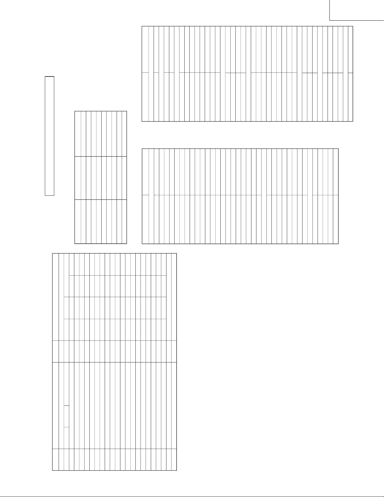
ITEM EEPROM SETTING DATA RANGE IC OSD INITIAL DATA SETTING DATA
A001 RF-AGC 0…63 UOC-TV RF-AGC 32 19
A002 RF AGC PIP 0…63 PIP-IF RF AGC PIP 0 0
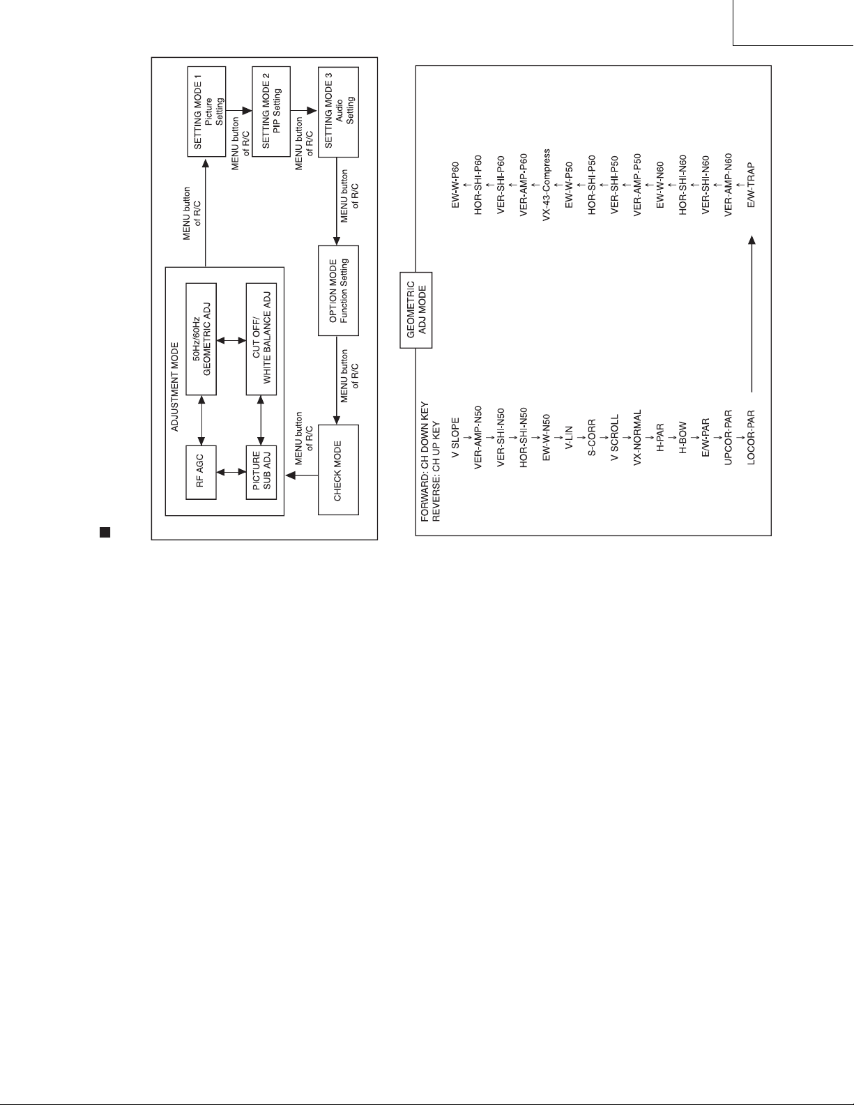
A003 V SLOPE 0…63 UOC-TV V SLOPE 40 35
A004 VER-AMP-N50 0…63 UOC-TV VER-AMP-N50 32 21
A005 VER-SHI-N50 0…63 UOC-TV VER-SHI-N50 25 25
A006 HOR-SHI-N50 0…63 UOC-TV HOR-SHI-N50 45 44
A007 EW-W-N50 0…63 UOC-TV EW-W-N50 40 40
A008 V-LIN 0…63 UOC-TV V-LIN 32 32
A009 S-COR 0…63 UOC-TV S-COR 30 32
A010 V SCROLL 0…63 UOC-TV V SCROLL 32 32
A011 VX-NORMAL 0…63 UOC-TV VX-NORMAL 32 32
A012 H-PAR 0…63 UOC-TV H-PAR 35 24
A013 H-BOW 0…63 UOC-TV H-BOW 25 28
A014 E/W-PAR 0…63 UOC-TV E/W-PAR 35 42
A015 UPCOR-PAR 0…63 UOC-TV UPCOR-PAR 45 47
A016 LOCOR-PAR 0…63 UOC-TV LOCOR-PAR 42 44
A017 E/W-TRAP 0…63 UOC-TV E/W-TRAP 32 32
A018 VER-AMP-N60 0…63 UOC-TV VER-AMP-N60 32 22
A019 VER-SHI-N60 0…63 UOC-TV VER-SHI-N60 25 24
A020 HOR-SHI-N60 0…63 UOC-TV HOR-SHI-N60 45 49
A021 EW-W-N60 0…63 UOC-TV EW-W-N60 40 41
A022 VER-AMP-P50 0…63 UOC-TV VER-AMP-P50 32 21
A023 VER-SHI-P50 0…63 UOC-TV VER-SHI-P50 32 25
A024 HOR-SHI-P50 0…63 UOC-TV HOR-SHI-P50 32 44
A025 EW-W-P50 0…63 UOC-TV EW-W-P50 32 40
A026 VX-43-COMPRESS 0…63 UOC-TV VX-43-COMPRESS 32 5
A027 VER-AMP-F50 0…63 UOC-TV VER-AMP-F50 32 32
A028 VER-SHI-F50 0…63 UOC-TV VER-SHI-F50 32 32
A029 HOR-SHI-F50 0…63 UOC-TV HOR-SHI-F50 32 32
A030 EW-W-F50 0…63 UOC-TV EW-W-F50 32 32
A031 VER-AMP-S50 0…63 UOC-TV VER-AMP-S50 32 32
A032 VER-SHI-S50 0…63 UOC-TV VER-SHI-S50 32 32
A033 HOR-SHI-S50 0…63 UOC-TV HOR-SHI-S50 32 32
A034 EW-W-S50 0…63 UOC-TV EW-W-S50 32 32
A035 SUB-SLOPE-S 0…63 UOC-TV SUB-SLOPE-S 32 32
A036 SUB-VX-S 0…63 UOC-TV SUB-VX-S 32 32
A037 VER-AMP-C50 0…63 UOC-TV VER-AMP-C50 32 32
A038 VER-SHI-C50 0…63 UOC-TV VER-SHI-C50 32 32
A039 HOR-SHI-C50 0…63 UOC-TV HOR-SHI-C50 34 34
A040 EW-W-C50 0…63 UOC-TV EW-W-C50 32 32
A041 SUB-SLOPE-C 0…63 UOC-TV SUB-SLOPE-C 32 32
A042 SUB-VX-C 0…63 UOC-TV SUB-VX-C 32 32
A043 VER-AMP-P60 0…63 UOC-TV VER-AMP-P60 32 22
A044 VER-SHI-P60 0…63 UOC-TV VER-SHI-P60 32 24
A045 HOR-SHI-P60 0…63 UOC-TV HOR-SHI-P60 32 49
A046 EW-W-P60 0…63 UOC-TV EW-W-P60 32 41
A047 VER-AMP-F60 0…63 UOC-TV VER-AMP-F60 32 32
A048 VER-SHI-F60 0…63 UOC-TV VER-SHI-F60 32 32
A049 HOR-SHI-F60 0…63 UOC-TV HOR-SHI-F60 32 32
A050 EW-W-F60 0…63 UOC-TV EW-W-F60 32 32
A051 VER-AMP-S60 0…63 UOC-TV VER-AMP-S60 32 32
A052 VER-SHI-S60 0…63 UOC-TV VER-SHI-S60 32 32
A053 HOR-SHI-S60 0…63 UOC-TV HOR-SHI-S60 32 32
A054 EW-W-S60 0…63 UOC-TV EW-W-S60 32 32
A055 VER-AMP-C60 0…63 UOC-TV VER-AMP-C60 32 32
A056 VER-SHI-C60 0…63 UOC-TV VER-SHI-C60 32 32
A057 HOR-SHI-C60 0…63 UOC-TV HOR-SHI-C60 32 32
A058 EW-W-C60 0…63 UOC-TV EW-W-C60 32 32
A059 OF-ROTATE 0…127 UOC-TV OF-ROTATE 63 0
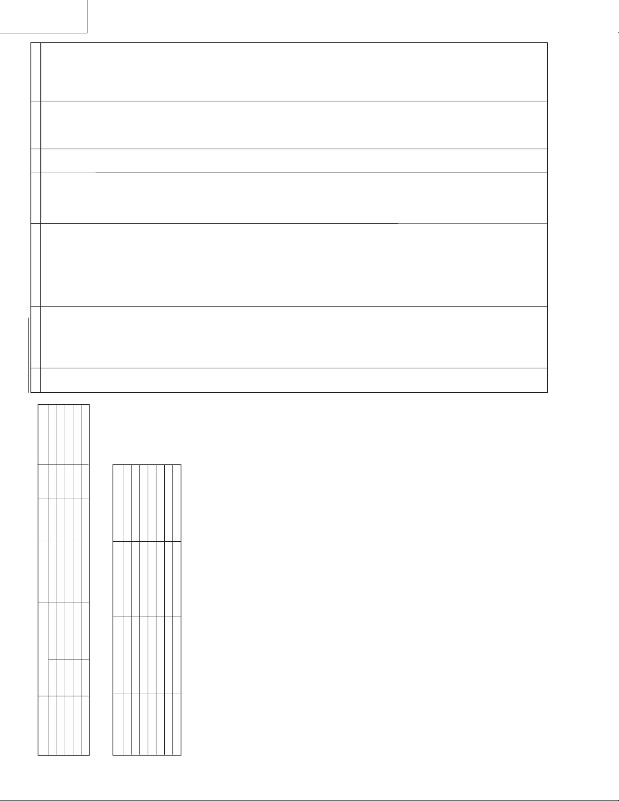
Adjustment Mode Items
ITEM EEPROM SETTING DATA RANGE IC OSD INITIAL DATA SETTING DATA
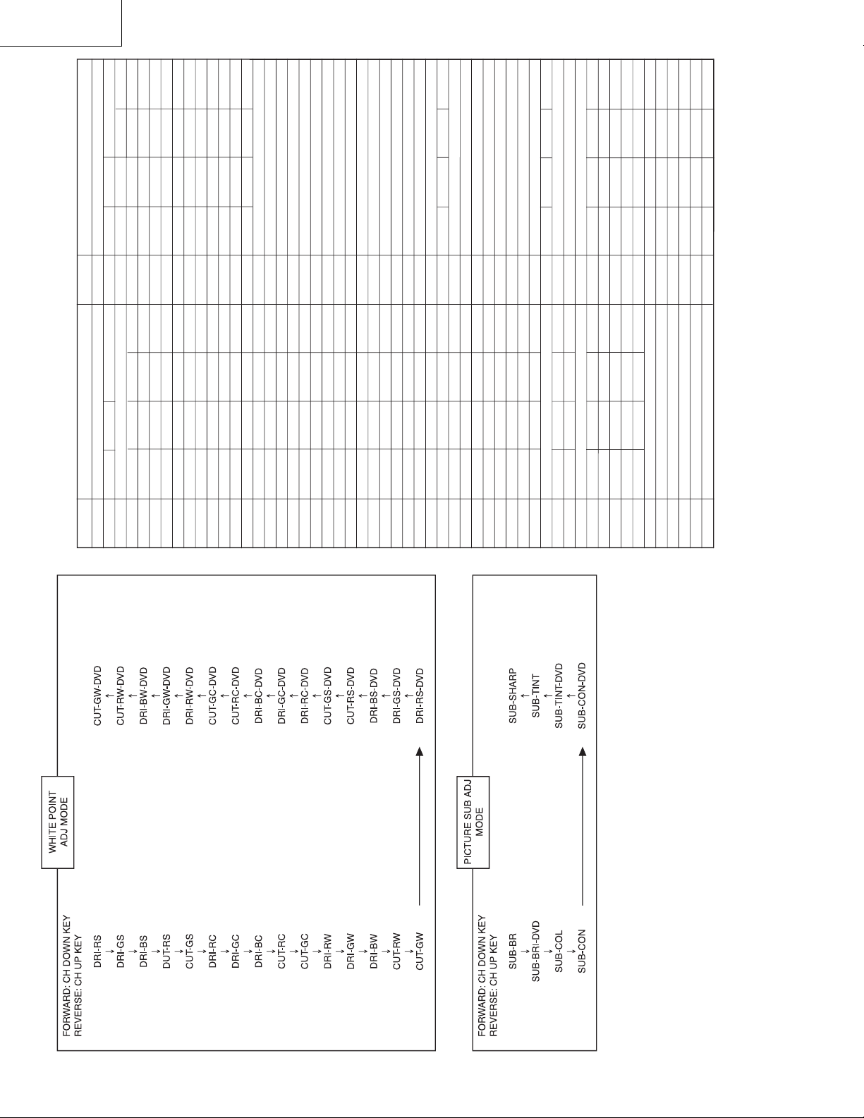
A060 DRI-RS 0…63 UOC-TV DRI-RS 32 32
A061 DRI-GS 0…63 UOC-TV DRI-GS 32 32
A062 DRI-BS 0…63 UOC-TV DRI-BS 32 32
A063 CUT-RS 0…63 UOC-TV CUT-RS 32 32
A064 CUT-GS 0…63 UOC-TV CUT-GS 32 32
A065 DRI-RC 0…63 UOC-TV DRI-RC 32 32
A066 DRI-GC 0…63 UOC-TV DRI-GC 32 32
A067 DRI-BC 0…63 UOC-TV DRI-BC 32 32
A068 CUT-RC 0…63 UOC-TV CUT-RC 32 32
A069 CUT-GC 0…63 UOC-TV CUT-GC 32 32
A070 DRI-RW 0…63 UOC-TV DRI-RW 32 32
A071 DRI-GW 0…63 UOC-TV DRI-GW 32 32
A072 DRI-BW 0…63 UOC-TV DRI-BW 32 32
A073 CUT-RW 0…63 UOC-TV CUT-RW 32 32
A074 CUT-GW 0…63 UOC-TV CUT-GW 32 32
A075 DRI-RS-DVD 0…63 UOC-TV DRI-RS-DVD 32 32
A076 DRI-GS-DVD 0…63 UOC-TV DRI-GS-DVD 32 32
A077 DRI-BS-DVD 0…63 UOC-TV DRI-BS-DVD 32 32
A078 CUT-RS-DVD 0…63 UOC-TV CUT-RS-DVD 32 32
A079 CUT-GS-DVD 0…63 UOC-TV CUT-GS-DVD 32 32
A080 DRI-RC-DVD 0…63 UOC-TV DRI-RC-DVD 32 32
A081 DRI-GC-DVD 0…63 UOC-TV DRI-GC-DVD 32 32
A082 DRI-BC-DVD 0…63 UOC-TV DRI-BC-DVD 32 32
A083 CUT-RC-DVD 0…63 UOC-TV CUT-RC-DVD 32 32
A084 CUT-GC-DVD 0…63 UOC-TV CUT-GC-DVD 32 32
A085 DRI-RW-DVD 0…63 UOC-TV DRI-RW-DVD 32 32
A086 DRI-GW-DVD 0…63 UOC-TV DRI-GW-DVD 32 32
A087 DRI-BW-DVD 0…63 UOC-TV DRI-BW-DVD 32 32
A088 CUT-RW-DVD 0…63 UOC-TV CUT-RW-DVD 32 32
A089 CUT-GW-DVD 0…63 UOC-TV CUT-GW-DVD 32 32
A090 SUB-BRI 0…63 UOC-TV SUB-BRI 32 39
A091 SUB-BRI-DVD 0…63 UOC-TV SUB-BRI-DVD 32 38
A092 SUB-COL 0…63 UOC-TV SUB-COL 32 34
A093 SUB-CON 0…63 UOC-TV SUB-CON 32 48
A094 SUB-CON-DVD 0…63 UOC-TV SUB-CON-DVD 32 49
A095 SUB-TINT-DVD 0…63 UOC-TV SUB-TINT-DVD 32 34
A096 SUB-TINT 0…63 UOC-TV SUB-TINT 32 34
A097 SUB-SHARP 0…63 UOC-TV SUB-SHARP 32 12
A098 P-POSOFH-50 0…31 PIP P-POSOFH-50 0 16
A099 P-POSOFV-50 0…7 PIP P-POSOFV-50 0 3
A100 P-POSOFH-60 0…31 PIP P-POSOFH-60 0 16
A101 P-POSOFV-60 0…7 PIP P-POSOFV-60 0 3
A102 P-SUB-TINT 0…63 PIP P-SUB-TINT 0 32
A103 P-CON-CTM 0…15 PIP P-CON-CTM 0 4
A104 P-CON-DYN 0…15 PIP P-CON-DYN 0 4
A105 P-CON-STD 0…15 PIP P-CON-STD 0 4
A106 P-CON-SOFT 0…15 PIP P-CON-SOFT 0 4
A107 P-SUB-BRI 0…15 PIP P-SUB-BRI 0 4
A108 P-BKGD-R 0…15 PIP P-BKGD-R 0 4
A109 P-BKGD-G 0…15 PIP P-BKGD-G 0 4
A110 P-BKGD-B 0…15 PIP P-BKGD-B 0 4
A111 P-SUB-COL 0…15 PIP P-SUB-COL 0 7
A112 P-SUB-SHP 0…7PIP P-SUB-SHP 0 3
A113 VSD 0/1 UOC-TV VSD 0 0
A114 CUT OFF 0…63 UOC-TV CUT OFF 6 6
A115 VG2 0/1 UOC-TV VG2 0 1
A116 DCXO 0…127 UOC-TV DCXO 79 69
A117 DCXO-AUTO 0/1 UOC-TV DCXO-AUTO 0 0