2
LC-37DB5U
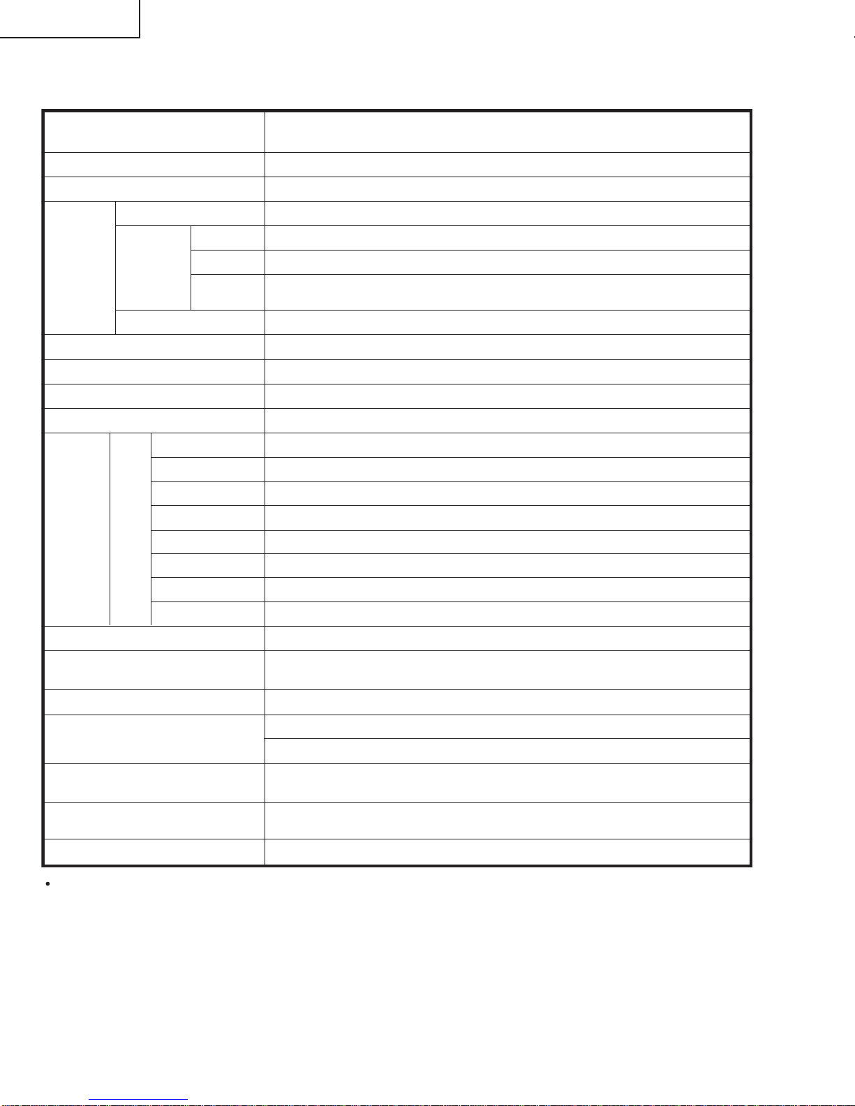
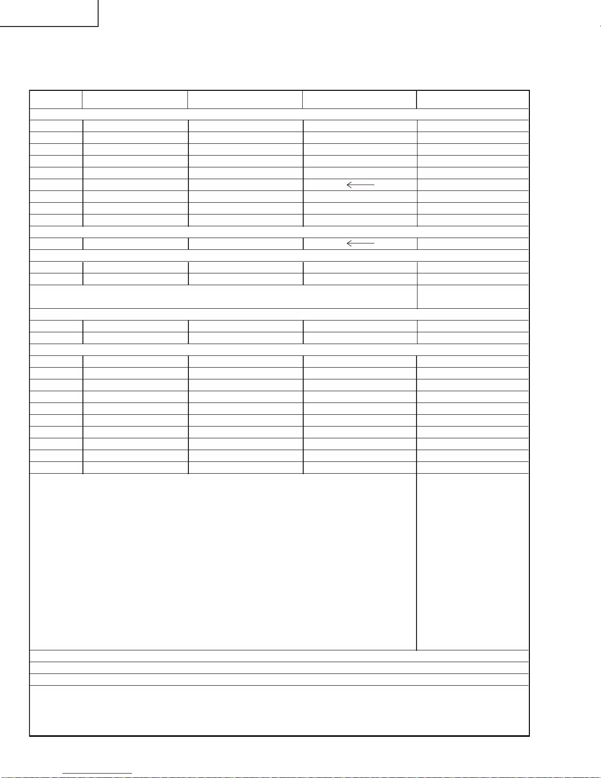
LIST OF CHANGED PARTS
LC-37D4U → LC-37DB5U
Ref.No. Description LC-37D4U LC-37DB5U Note
PWB ASSEMBLIES
DIGITAL Unit DUNTKD331FE14 DUNTKD331FE16 *Some parts changed
AV Unit DUNTKD352DE19 DUNTKD352WE03 *Some parts changed
KEY Unit DUNTKD353DE19 DUNTKD353WE01 No parts changed
R/C, LED Unit DUNTKD354DE19 DUNTKD354WE01 *Some parts changed
MAIN Unit DUNTKD376FE06 DUNTKD376FM07 No parts changed
POWER Unit RDENCA140WJQZ
LCD PANEL
37 WIDE LCD PANEL MODULE Unit
RLCUCA026WJZZ
AV Unit
R3926 Metal Oxide VRS-CY1JF222JY VRS-CY1JF102JY *Change
R3930 Metal Oxide VRS-CY1JF682JY VRS-CY1JF102JY *Change
These parts is deleted from “LC-37D4U”. *Delete
Q1110, L1103, C1110, C1113, R1114, R1118, UNT1101
R/C, LED Unit
D103 Diode RH-PXA087WJZZY RH-PXA089WJZZY *Change
R108 Metal Oxide VRS-CY1JF911JY VRS-CY1JF561JY *Change
DIGITAL Unit
R8106 Metal Oxide VRS-CZ1JF000JY VRS-CZ1JF470JY *Change
R8107 Metal Oxide VRS-CH1JF000JY VRS-CH1JF470JY *Change
R8125 Metal Oxide VRS-CH1JF103JY VRS-CH1JF470JY *Change
R8164 Metal Oxide VRS-CZ1JF000JY VRS-CZ1JF470JY *Change
R8198 Metal Oxide VRS-CZ1JF103JY VRS-CZ1JF470JY *Change
R8208 Metal Oxide VRS-CZ1JF103JY *Add
R8209 Metal Oxide VRS-CZ1JF103JY *Add
R9537 Metal Oxide VRS-CH1JF470JY VRS-CH1JF000JY *Change
R9538 Metal Oxide VRS-CH1JF470JY VRS-CH1JF000JY *Change
R9539 Metal Oxide VRS-CZ1JF000JY *Add
These parts is deleted from “LC-37D4U”. *Delete
CABINET AND MECHANICAL PARTS
Please refer to a Parts list.
PACKING PARTS AND ACCESSORIES
Please refer to a Parts list.
IC8051, IC8052, IC9402, IC9403, IC9405, IC9501, IC9502, IC9503, IC9701, IC9702, D9701, D9702, D9703,
FL8051, L8051, L8052, L8053, L8054, L8055, L8056, L8057, L8058, L8059, L8060, L8061, L9702, L9703,
C8051, C8052, C8053, C8054, C8055, C8056, C8057, C8058, C8059, C8060, C8061, C8062, C8063, C8064,
C8065, C8066, C8067, C8068, C8069, C8070, C8071, C8072, C8073, C8074, C8075, C8076, C8077, C8078,
C8079, C8080, C8081, C8082, C8083, C8084, C8085, C8086, C8087, C9404, C9405, C9406, C9407, C9408,
C9409, C9410, C9411, C9413, C9417, C9501, C9502, C9503, C9504, C9505, C9506, C9507, C9508, C9509,
C9510, C9511, C9512, C9513, C9514, C9515, C9516, C9517, C9518, C9701, C9702, C9703, C9704, C9705,
C9706, C9707, C9708, C9709, C9711, C9714, R8051, R8052, R8053, R8054, R8056, R8057, R8101, R8105,
R8112, R8117, R8124, R8132, R8414, R8415, R9124, R9125, R9126, R9401, R9402, R9403, R9404, R9405,
R9407, R9408, R9409, R9410, R9411, R9413, R9414, R9418, R9501, R9502, R9503, R9504, R9505, R9507,
R9509, R9511, R9513, R9515, R9517, R9519, R9521, R9523, R9524, R9525, R9526, R9527, R9528, R9701,
R9702, R9704, R9705, R9706, R9710, R9711, FB9401, FB9402, FB9403, FB9701, J8052, SC9401, SC9501,
LUG9401, LUG9402