SX-68JF200
3
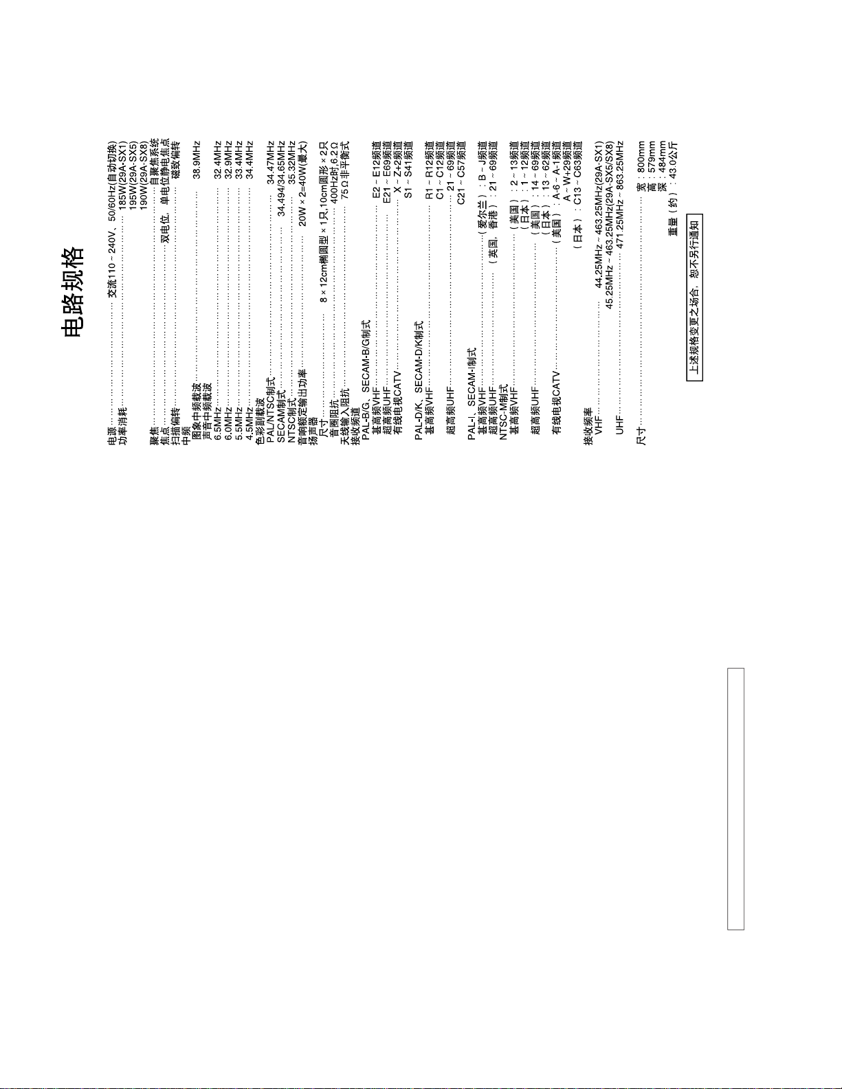
ELECTRICAL SPECIFICATIONS
Power Input .............................................................................................. AC 110-240V, 50/60Hz (Auto)
Power Consumption ...................................................................................................... 185W(29A-SX1)
195W(29A-SX5)
190W(29A-SX8)
Convergence.................................................................................................. Self Convergence System
Focus ......................................................................................... Bi-Potential, Uni-Potential Electroslatic
Sweep Deflection ......................................................................................................................Magnetic
Intermediate Frequency
Picture IF Carrier.................................................................................................................. 38.9 MHz
Sound IF Carrier
6.5 MHz .............................................................................................................................. 32.4 MHz
6.0 MHz .............................................................................................................................. 32.9 MHz
5.5 MHz .............................................................................................................................. 33.4 MHz
4.5 MHz .............................................................................................................................. 34.4 MHz
Colour Sub-Carrier
PAL/NTSC ........................................................................................................................ 34.47 MHz
SECAM................................................................................................................. 34.494/34.65 MHz
NTSC................................................................................................................................ 35.32 MHz
Audio Power Output Rating............................................................................. 20W x 2 total 40W (Max)
Speaker
Size ........................................................................................8 x 12 cm x 2pcs, 10cm Round x 2pcs.
Speaker Box Unit Impedance ................................................................................. 6.2 ohm at 400Hz
Aerial Input Inpedance ............................................................................................ 75 ohm Unbalanced
Receiving Channels
PAL-B/G, SECAM-B/G
VHF ...........................................................................................................................E2 thru E12
UHF .........................................................................................................................E21 thru E69
CATV ...........................................................................................................................X thru Z + 2,
S1 thru S41
PAL-D/K, SECAM-D/K
VHF ...........................................................................................................................R1 thru R12,
C1 thru C12
UHF ........................................................................................................................... 21 thru 69,
C21 thru C57
PAL-I, SECAM-I
VHF ............................................................................................... (IRELAND): B thru J
UHF ................................................................................................(U.K.,H.K.): 21 thru 69
NTSC-M
VHF ..........................................................................................................(US): 2 thru 13
(JAPAN): 1 thru 12
UHF ..........................................................................................................(US): 14 thru 69
(JAPAN): 13 thru 62
CATV ........................................................................................................(US): A-6 thru A-1
A thru W+29
(JAPAN): C13 thru C63
Receiving Frequency
VHF ................................................................................ 44.25 MHz thru 463.25 MHz(29A-SX1)
45.25 MHz thru 463.25 MHz(29A-SX5/SX8)
UHF ...................................................................................................... 471.25 MHz thru 863.25 MHz
Dimensions.................................................................................................................. Width : 800mm
Height : 579mm
Depth : 484mm
Weight (Approx) : 43.0kg
Specifications are subject to change without notice.