7
SX-68JS7
SX-68JS9
(To be done after the purity adjustment)
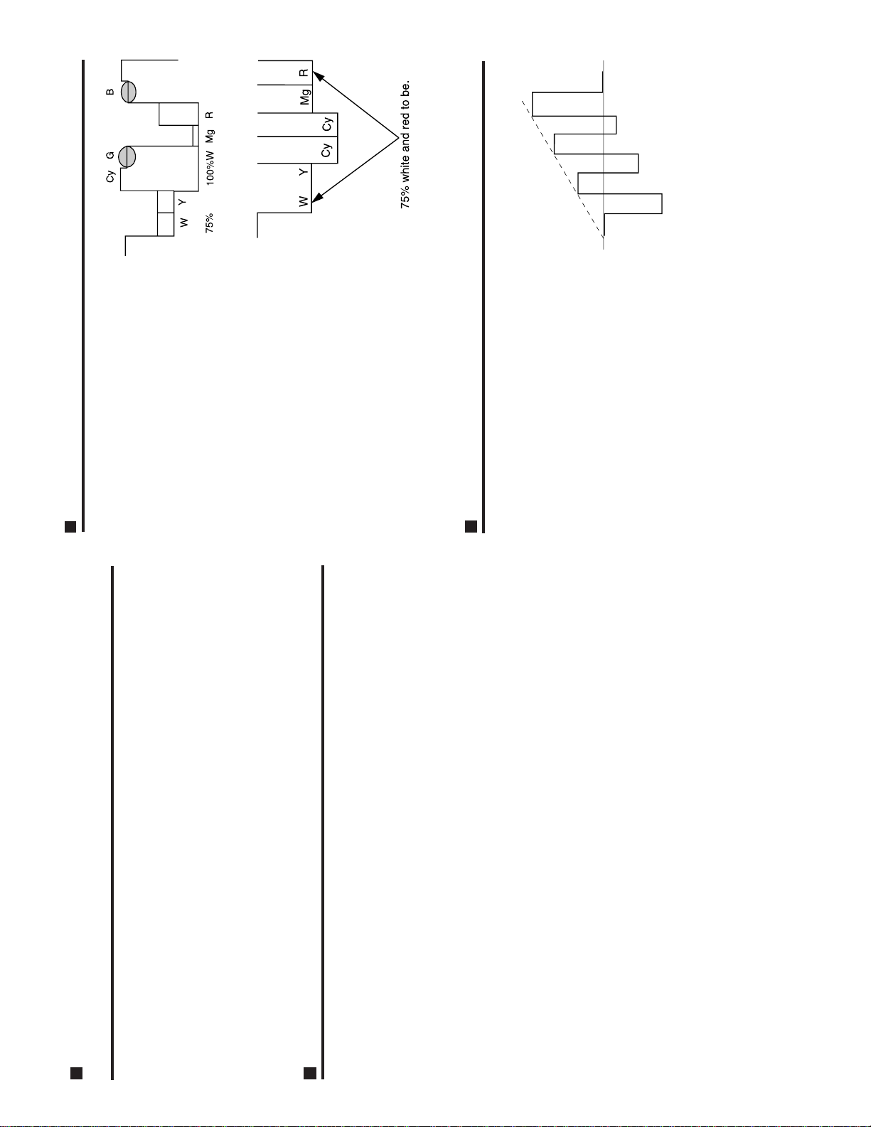
CONVERGENCE ADJUSTMENT
1. Receivethe "CROSSHATCHPATTERN" signal.
2. Using the remote controller, call the Normal
mode.
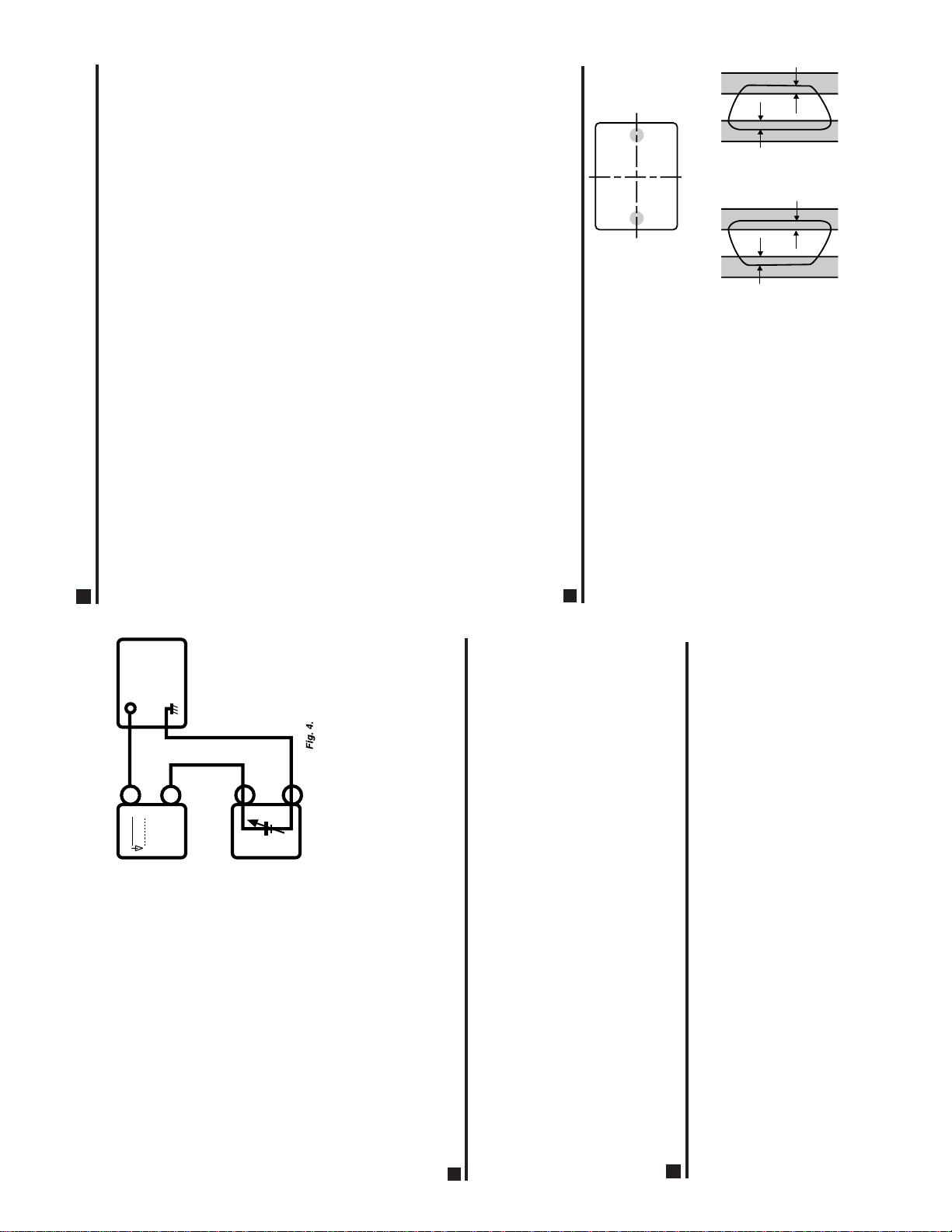
STATIC CONVERGENCE
1. Turn the 4-pole magnet to a proper opening
angle in order to superimpose the blue and red
colours.
2. Turn the 6-pole magnet to a proper opening
angle in order to superimpose the green colour
over the blue and red ones.
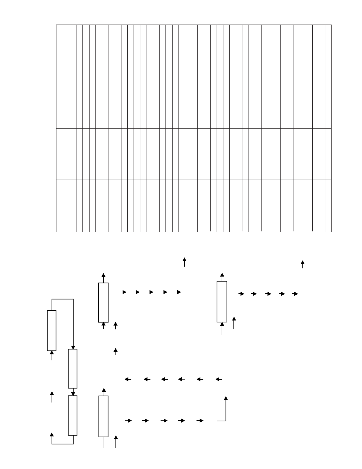
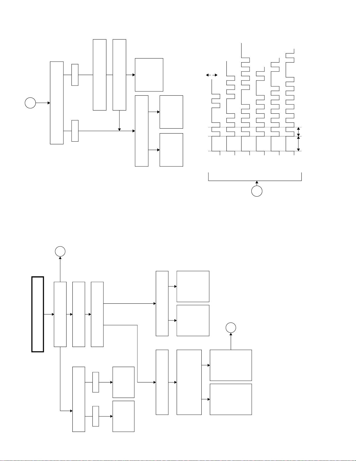
DYNAMIC CONVERGENCE
1. Adjust the convergence on the fringes of the
screen in the following steps.
a) Fig.a:Drivethewedge atpoint"a" andswing
the deflection coil upward.
b) Fig.b:D
rive the wedge at points "b" and "c" and
swing the deflection coil down ward.
c) Fig. c: Drive the"c"wedgedeeperand swing
the deflection coil rightward.
d) Fig. d: Drivethe "b"wedgedeeper andswing
the deflection coil leftward.
2. Fix all the wedges on the CRT and apply glass
tape over them.
3. Apply lacquer to the deflection yoke lock screw,
magnetunit (purity, 4-poleand6-pole magnets)
and magnet unit lock screw.
B G R
B G R
R G B
R G B
Fig. a Fig. b
Fig. c Fig. d
B
G
R
B
G
R
R
G
B
R
G
B
Wedge "a"
Wedge "b" Wedge "c"
About 100°
About 100°
Lacquer
4-pole magnet
6-pole magnet
4 - pole magnet
CRT neck
Lacquer
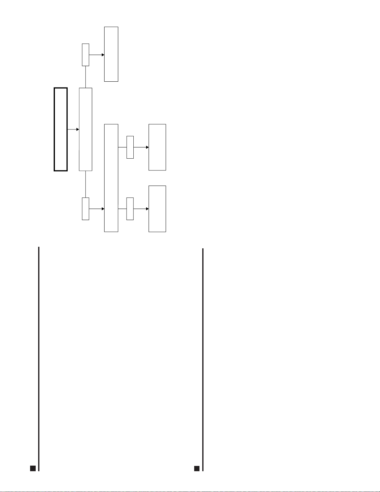
CRT CUT-OFF, BACKGROUND AND SUB-CONTRAST
ADJUSTMENT
1. CRT CUT-OFF ADJUSTMENTS
Adjusting Point
Sub-Brightness: R890
1 Receive "MONOSCOPE PATTERN" signal.
2. Using the remote controller, call up the P-NORM mode.
3. Turn on the service switch and select the cut-off/back-
ground mode.
4. Connect the oscilloscope to TP852 (RED cathode).
5. Set the screen control to 0/10 position.
6. Press the "9" key on the remote controller to reach the
horizontal centering mode.
7. Adjustthe sub-brightnesscontrol (R890) sothattheblank-
ing pulse on the oscilloscope screen be 10 ±1Vp-p.
8. Disconnect the oscilloscope from TP852.
2. WHITE BALANCE and BACKGROUND I2C BUS ADJUSTMENT
9. Turn the screen control clockwise until the horizontal raster of the first glimmering colour
becomes slightly visible.
10. Adjust the cut-off data of the other two colours until the horizontal raster becomes whitish.
Note:The data can be turned up and down with the above keys.
• R CUT OFF UP "1" key • G CUT OFF DOWN "5" key
• R CUT OFF DOWN "4" key • B CUT OFF UP "3" key
• G CUT OFF UP "2" key • B CUT OFF DOWN "6" key
11. Turn the screen control counterclockwise until the horizontal raster disappears.
Note:
Before starting this adjustment, warm up the unit for 30 minutes or longer at a beam
current of 1300
µ
A.
12. Press the "9" key on the remote controller to call the normal mode.
13.
Using the remote controller, call the sub-brightness setting mode.(Receive the E-2CH signal).
14. Set the sub-brightness data so that the second black portion of the window pattern looks
sinking.The service mode adjustment in the above steps (13) and (14) should be carried
out after the white balance and background adjustments.
Note: Make sure the sub-brightness data is smaller than 129 (initial value 127). If above
130,go back to Step(7).Readjust the sub-brightness control(R890) so that the blank-
ing pulse level on the oscilloscope screen be within +0.5Vp-p from the first-adjusted
level. Now take Step(8) and the following over again. (The sub-brightness data is
adjusted to about 20 steps lower.)
• If the sub-brightness data is above 130,there will be problem with the user's bright-
ness control.
1. Receive the "MONOSCOPE PATTERN" signal.
2. Using the remote controller, call the Video Normal mode.
3. Connect the beam ammeter betweenTP601 and TP602.
4. Roughly adjust R1631 (sub-contrast control) to have a beam current of about 1.6 mA.
5. Adjust the G-drive and B-drive data to have a colour temperature of 12300ºK (white).
•12300K°X: 0.272
Y: 0.275
(with a Minolta colour temperture meter)
Note:The data can be turned up and down with the above keys.
• G-DRIVE UP "7" key • B-DRIVE UP "8" key
• G-DRIVE DOWN " " key • B-DRIVE DOWN "0" key
6. Adjust the contrast and brightness controls to have a beam current of 200 µA. Now check
the background clour. If the colour temperature is not 12300ºK, go back to No. 1 on the
preceding page.
Note:Before starting this adjustment,warm up the unit for 30 minutes or longer at a beam
current of 1300µA.