Sharpe SEA ? User manual

It is the responsibility of the customer to determine the suitability of Sharpe®Valves products in their particular application.
Disclaimer: Supplier shall not be liable or responsible for omissions or errors in its bulletin.
IM-SEA-1
10-12-17 / Rev. 1
Page 1 of 16
INSTALLATION, OPERATIONS
AND MAINTENANCE FOR SHARPE®
SEA ELECTRIC ACTUATORS
2701 Busse Road Elk Grove Village, Illinois 60007
Phone: (877) 774-2773
Fax: (708) 562-9250
www.sharpevalves.com

It is the responsibility of the customer to determine the suitability of Sharpe®Valves products in their particular application.
Disclaimer: Supplier shall not be liable or responsible for omissions or errors in its bulletin.
IM-SEA-1
10-12-17 / Rev. 1
Page 2 of 16
OVERVIEW
Sharpe®electric quarter-turn actuators offer a wide range of torque output models. The product
design is based on a self-locking worm drive principal, which provides for a smooth running,
dependable, robust drive system. All models are ISO 5211 compliant and most have a visual
position indicator on top of actuator cover and manual override
LUBRICATION
The gearbox of the Sharpe actuator is enclosed, and it has already been lubricated sufficiently
with high temperature lubricant at the factory sufficient for use for up to two years.
IMPORTANT NOTICES & MAINTENANCE
Notices:
Make sure the voltage is correct before wiring.
Turn off power before for maintenance purposes.
Seal the casing and conduit entrance after wiring to prevent dust or water contamination.
The angle of installation must between 0~180°. Do not install upside down or below the
horizontal.
Do not install when hazardous or explosive gases may be present.
The frequency of open and close is restricted based on duty cycle. Avoid too high
frequency.
When more than one electric actuator needs to operate simultaneously, please connect
individually.
Always connect the ground wire to the inside of the electric actuator.
Not intended for vacuum spaces and avoid installing near explosive atmospheres.
To avoid functional failure caused by statics, do not touch any components on the PCB
with metal tools or bare hands.
Storage:
The actuator should be placed in a clean and dry place, and protected from the weather
and extreme vibration.
If actuator needs be stored outside, it must be protected from excess moisture, dust,
and weather.

It is the responsibility of the customer to determine the suitability of Sharpe®Valves products in their particular application.
Disclaimer: Supplier shall not be liable or responsible for omissions or errors in its bulletin.
IM-SEA-1
10-12-17 / Rev. 1
Page 3 of 16
INSTALLATION
1. Before mounting actuator, verify that the torque requirement is less than the output
torque of the actuator. (The suggested safety factor is 30% of the max. torque of
valve.)
1. For example :
If the maximum valve torque is 80Nm - 80 × 1.3(safety factor) =104 Nm
104Nm <150Nm SEA 13 is OK!
104Nm >90Nm SEA 8 is not OK!
2. Check if the output shaft fits to the stem of valve before inserting into actuator. Please
use mounting plate or adapter to connect if it does not match.
3. Insert output shaft adapter into actuator. Make sure it fits satisfactory.
4. Determine that actuator position, open or closed, matches with position of equipment
prior to mounting. Use manual override to change position if necessary.
5. Remove valve’s manual device and mount on the proper connection.
6. Check again that the valve and actuator are in the same position.
7. Install the actuator to valve directly or with mounting kits, then tighten all screws and
nuts.
8. Remove actuator cover.
9. Wire actuator using the wiring diagram inside cover.
10.Supply power to actuator.
11.Make sure if it is needed to calibrate the fully-open or fully-closed position of the
actuator.
12.If the actuator is modulating type make sure set the required settings.
13.Replace cover and secure cover screws.

It is the responsibility of the customer to determine the suitability of Sharpe®Valves products in their particular application.
Disclaimer: Supplier shall not be liable or responsible for omissions or errors in its bulletin.
IM-SEA-1
10-12-17 / Rev. 1
Page 4 of 16
SPECIFICATIONS
12V/24V
Model
No.
Max Torque
Speed
(90°)
Motor
Power
12V DC/AC
24V DC/AC
Nm
lb-in
Run
Start
Lock
Run
Start
Lock
SEA 3
35
310
15s
10W
1.9A
2.0A
2.8A
1.1A
1.1A
1.6A
SEA 4
50
443
20s
10W
1.3A
1.5A
2.8A
0.8A
0.9A
1.6A
SEA 8
90
797
15s
40W
3.4A
5.2A
16.5A
2.2A
4.5A
14.5A
SEA 13
150
1328
22s
40W
4.4A
4.9A
16.5A
2.4A
5.0A
14.5A
SEA 35
400
3540
16s
80W
16.1A
16.1A
33.0A
8.5A
9.2A
30.0A
SEA 44
500
4425
22s
80W
14.1A
13.5A
33.0A
7.5A
9.0A
30.0A
SEA 57
650
5750
28s
80W
12.3A
12.5A
33.0A
7.0A
8.5A
30.0A
SEA 88
1000
8850
46s
80W
6.8A
7.8A
30.0A
SEA 132
1500
13275
46s
80W
25A
26A
59A
8.1A
8.0A
30.0A
SEA 177
2000
17700
58s
80W
8.8A
11.0A
26.0A
SEA 221
2500
22125
58s
80W
28A
60A
59A
11.8A
11.0A
26.0A
SEA 265
3000
26550
58s
220W
15.1A
11.0A
33.0A
SEA 310
3502
31000
58s
220W
17.8A
12.0A
33.0A
Single Phase
Model
No.
Max Torque
Speed
(90°)
Motor
Power
110V Current
220V-240V Current
Nm
lb-in
60
Hz
50
Hz
Run
Start
Lock
Run
Start
Lock
SEA 3
35
310
12s
13s
10W
0.6A
0.6A
0.7A
0.3A
0.4A
0.4A
SEA 4
50
443
20s
24s
10W
0.6A
0.6A
0.7A
0.3A
0.4A
0.5A
SEA 8
90
797
15s
17s
40W
1.0A
1.8A
1.6A
0.5A
0.8A
0.9A
SEA 13
150
1328
22s
26s
40W
1.2A
1.8A
1.6A
1.0A
1.2A
0.9A
SEA 35
400
3540
16s
18s
80W
1.9A
3.8A
3.6A
1.1A
2.0A
2.2A
SEA 44
500
4425
22s
25s
80W
2.0A
3.8A
3.6A
1.1A
2.0A
2.2A
SEA 57
650
5750
28s
31s
80W
2.1A
3.8A
3.6A
1.1A
2.0A
2.2A
SEA 88
1000
8850
46s
55s
120W
3.1A
8.5A
9.0A
1.4A
4.1A
5.0A
SEA 132
1500
13275
46s
55s
120W
3.3A
9.0A
9.0A
1.6A
4.4A
5.0A
SEA 177
2000
17700
58s
70s
180W
3.3A
5.8A
5.9A
2.1A
3.8A
3.6A
SEA 221
2500
22125
58s
70s
180W
4.0A
6.5A
5.9A
2.3A
4.0A
3.6A
SEA 265
3000
26550
58s
70s
180W
4.5A
3.5A
5.9A
2.5A
4.2A
3.6A
SEA 310
3502
31000
58s
70s
220W
4.0A
8.0A
7.5A
2.4A
4.4A
4.8A
Note:
RUN= Operating; START= Start to operate; LOCK= When you input power to the actuator and the actuator can’t operate.

It is the responsibility of the customer to determine the suitability of Sharpe®Valves products in their particular application.
Disclaimer: Supplier shall not be liable or responsible for omissions or errors in its bulletin.
IM-SEA-1
10-12-17 / Rev. 1
Page 5 of 16
TRAVEL CAM & LIMIT SWITCHES ADJUSTMENT
The travel cams are set to control the open and closed position of the
valve. LS1 & LS2 limit the maximum range by disabling the electric
motor.
LS3 & LS4 are optional. They allow external equipment to confirm
that the valve has reached the fully open and fully closed positions.
IMPORTANT: If LS3 & LS4 are fitted, they should be set to trip
prior to LS1 & LS2 to avoid over-travel.
A 2.5mm hex keywill be required to adjust cam settings.
Travel Cam Adjustment –SEA 3

It is the responsibility of the customer to determine the suitability of Sharpe®Valves products in their particular application.
Disclaimer: Supplier shall not be liable or responsible for omissions or errors in its bulletin.
IM-SEA-1
10-12-17 / Rev. 1
Page 6 of 16
TRAVEL CAM & LIMIT SWITCHES ADJUSTMENT (cont.)
Travel Cam Adjustment –SEA 4
Travel Cam Adjustment –SEA 8 - SEA310

It is the responsibility of the customer to determine the suitability of Sharpe®Valves products in their particular application.
Disclaimer: Supplier shall not be liable or responsible for omissions or errors in its bulletin.
IM-SEA-1
10-12-17 / Rev. 1
Page 7 of 16
TRAVEL CAM & TORQUE SWITCHES ADJUSTMENT
Travel Cam Adjustment –SEA 8 - SEA310
MODULATING CONTROL BOARD
INTERFACE
SEA 3 –SEA4
It is the responsibility of the customer to determine the suitability of Sharpe®Valves products in their particular application.
Disclaimer: Supplier shall not be liable or responsible for omissions or errors in its bulletin.
IM-SEA-1
10-12-17 / Rev. 1
Page 8 of 16
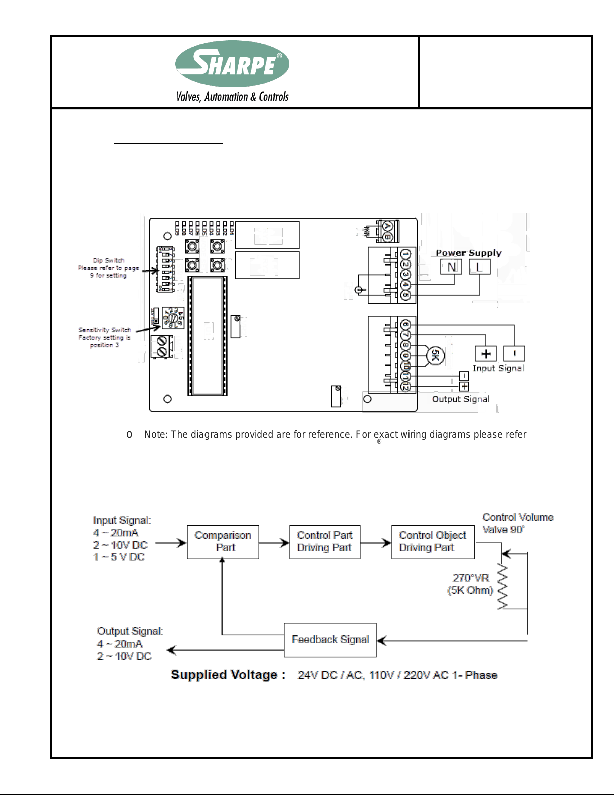
MODULATING CONTROL BOARD
INTERFACE (cont.)
SEA 8 –SEA 310
o Note: The diagrams provided are for reference. For exact wiring diagrams please refer to the
manual provided with the actuator or contact Sharpe®directly.
MODULATING CONTROL BOARD PROCEDURE

It is the responsibility of the customer to determine the suitability of Sharpe®Valves products in their particular application.
Disclaimer: Supplier shall not be liable or responsible for omissions or errors in its bulletin.
IM-SEA-1
10-12-17 / Rev. 1
Page 9 of 16
DIP SWITCH SETTING
IMPORTANT: DO NOT ALTER SWITCH POSITIONS WHILE ACTUATOR HAS POWER
S1 & S2:
o INPUT SIGNAL SELECT
4~20m/A set 1-ON / 2-OFF.
1~5V set 1-OFF / 2-OFF.
2~10V set 1-OFF / 2-ON
S3 & S4 & S5:
o OUTPUT SIGNAL SELECT
2-10V set 3-ON / 4-OFF / 5-ON.
4-20m/A set 3-OFF / 4-ON / 5-OFF.

It is the responsibility of the customer to determine the suitability of Sharpe®Valves products in their particular application.
Disclaimer: Supplier shall not be liable or responsible for omissions or errors in its bulletin.
IM-SEA-1
10-12-17 / Rev. 1
Page 10 of 16
DIP SWITCH SETTING (cont.)
Position Select:
o S6 ON
4mA, 2V, 1V = valve fully-open.
20mA, 10V, 5V = valve fully-closed.
S7 & S8 –Position Select when input signal fails
- Valve fully-closed set 7-ON / 8-OFF.
- Valve fully-open set 7-OFF / 8-ON.
- Valve stops set 7-ON / 8-ON or 7-OFF/ 8-OFF.
o S6 OFF
-closed.
-open.
S7 & S8 –Position Select when input signal fails
- Valve fully-closed set 7-OFF / 8-ON.
- Valve fully-open set 7-ON / 8-OFF.
- Valve stops set 7-ON / 8-ON or 7-OFF/ 8-OFF.
Even if S6 is adjusted, the feedback signal will not change.
SENSITIVITY SWITCH
Setting
o When switch is set to “1”:
The Highest Sensitive and the 0~90 degree can be divided up
to around 50 times movement.
o When switch is set to “0”:
The Lowest Sensitive and the 0~90 degree can be divided up
to around 10 times movement.
o The sensitivity decreases 5 times movement by sectors from SW1 to
SW2, SW2 to SW3, SW3 to SW4 and so on.

It is the responsibility of the customer to determine the suitability of Sharpe®Valves products in their particular application.
Disclaimer: Supplier shall not be liable or responsible for omissions or errors in its bulletin.
IM-SEA-1
10-12-17 / Rev. 1
Page 11 of 16
OPEN AND CLOSE SETTING
(SEA 3 & SEA 4)
The settings are set at factory, though in some cases re-set may be required when a
particular rate of signal is requested
Settings for OPEN and CLOSE
o The function of VR
Adjust output signal/input signal
- VR1—Adjust 10V, 20mA (Input signal: fully-open)
- VR51—Adjust 10V, 20mA (Output signal: fully-open)
- VR2 —Adjust 2V, 4mA (Input signal: fully-closed)
- VR52 —Adjust 2V, 4mA (Output signal: fully-closed)
Note: If it is necessary to adjust VR51 and VR52, VR1 and VR2 also need to be adjusted accordingly.
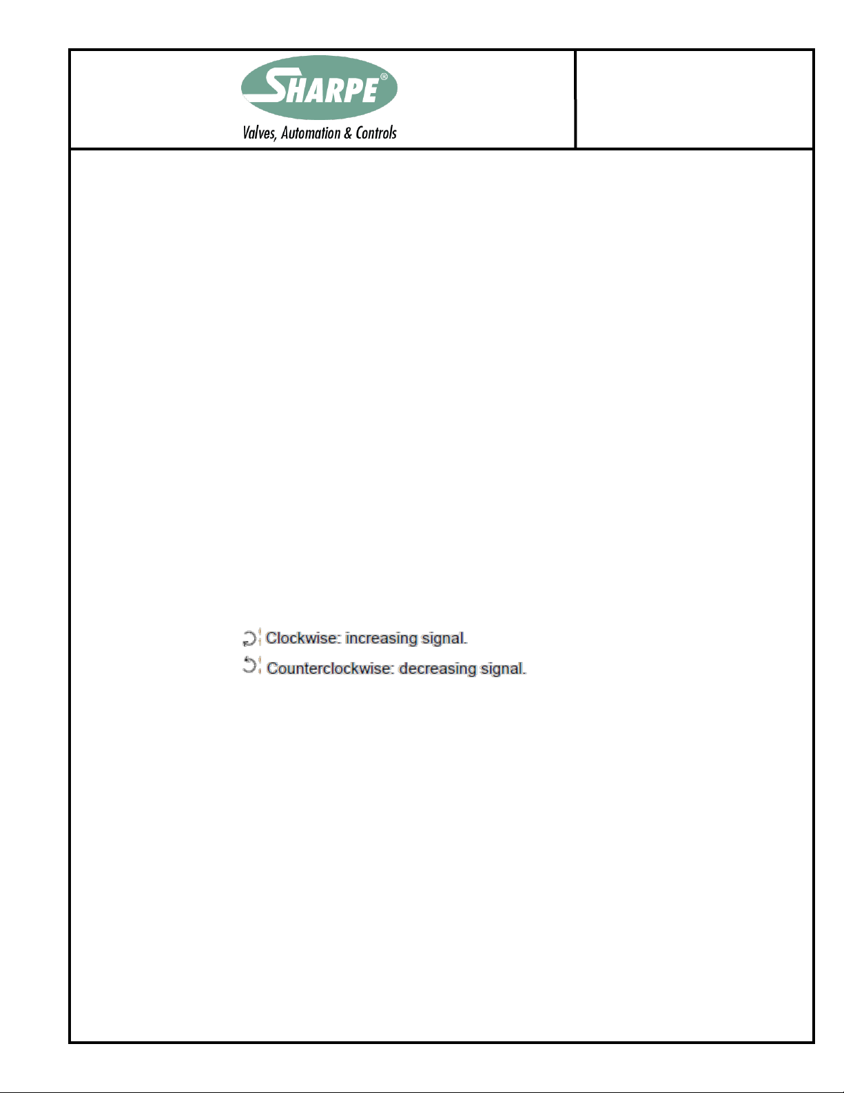
o Rotate VR1 counterclockwise until a light click is heard, then supply 10V (or
20mA) to modulating board. Slightly rotate VR1 clockwise until green LED keeps
on. Adjust VR51 to complete.
VR51:
-
-
o Rotate VR2 clockwise until a light click is heard, then supply 2V (or 4mA) to
modulating board. Slightly rotate VR2 counterclockwise until red LED keeps on.
Adjust VR51 to complete.
VR52:
-
-
It is the responsibility of the customer to determine the suitability of Sharpe®Valves products in their particular application.
Disclaimer: Supplier shall not be liable or responsible for omissions or errors in its bulletin.
IM-SEA-1
10-12-17 / Rev. 1
Page 12 of 16
OPEN AND CLOSE SETTING (cont.)
(SEA 8 & SEA 310)
The settings are set at factory, though in some cases re-set may be required when a
particular rate of signal is requested
Open Setting
o Keep pressing “SET” for 2 seconds, then LD 9 comes on, it will enter to the
manual mode.
o Keep pressing “UP” until actuator runs to fully-open position, LD2 comes on,
then supplies the input signal (5V or 10V or 20mA).
o Press “MODE” once. The OPEN setting is completed.
Close Setting
o Keep pressing “DOWN”, until actuator runs to fully-closed position, LD1
comes on , then supplies input signal (1V or 2V or 4mA).
o Press “MODE” once. The CLOSE setting is completed.
After completing the above settings, press “SET” once
Adjust Output Signal
o VR2:
MECHANICAL STOPS
Mechanical stops should only be reached during manual operation. They are
factory set, though in some cases adjustment may be required once a valve is fitted.
For Electric Operation:
o Please refer to Travel Cam & Limit Switches Adjustment section of this
document.

It is the responsibility of the customer to determine the suitability of Sharpe®Valves products in their particular application.
Disclaimer: Supplier shall not be liable or responsible for omissions or errors in its bulletin.
IM-SEA-1
10-12-17 / Rev. 1
Page 13 of 16
MECHANICAL STOPS (cont.)
For Manual Operation:
o Set the open stop.
Remove power from actuator.
Loosen locknut on the open stop stud (left side) and unscrew it a few
turns.
Unscrew the stop stud.
Manually turn the actuator to the desire limit position.
Screw in the stop stud until it contacts the internal cam, then reverse one
rotation.
Tighten the locknut.
Check that the electrical limit switches can still be reached.
o Set the close stop.
Remove power from actuator.
Loosen locknut on the close stop stud (right side) and unscrew it a few
turns.
Unscrew the stop stud.
Manually turn the actuator to the desire limit position.
Screw in the stop stud until it contacts the internal cam, then reverse one
rotation.
Tighten the locknut.
Check that the electrical limit switches can still be reached.
Failures to ensure the electrical limit switches are reached before the mechanical stops are
hit, when operating in electric mode, can cause personal injury or damage to the actuator.

It is the responsibility of the customer to determine the suitability of Sharpe®Valves products in their particular application.
Disclaimer: Supplier shall not be liable or responsible for omissions or errors in its bulletin.
IM-SEA-1
10-12-17 / Rev. 1
Page 14 of 16
LAMP SIGNALS

It is the responsibility of the customer to determine the suitability of Sharpe®Valves products in their particular application.
Disclaimer: Supplier shall not be liable or responsible for omissions or errors in its bulletin.
IM-SEA-1
10-12-17 / Rev. 1
Page 15 of 16
TROUBLE SHOOTING
On-Off controller:
.
.
.
.

It is the responsibility of the customer to determine the suitability of Sharpe®Valves products in their particular application.
Disclaimer: Supplier shall not be liable or responsible for omissions or errors in its bulletin.
IM-SEA-1
10-12-17 / Rev. 1
Page 16 of 16
TROUBLE SHOOTING (cont.)
Modulating controller:
This manual suits for next models
12
Table of contents
Popular Controllers manuals by other brands

Malmbergs
Malmbergs 99 170 21-23 instruction manual

Panasonic
Panasonic FP-XH Series user manual

Ingersoll-Rand
Ingersoll-Rand 150BMPC Series Installation and maintenance information

Wisy
Wisy ZETA 02 operating instructions

Kramer
Kramer SL-12 user manual

Motor Company Warehouse
Motor Company Warehouse SDS075OC400V10 user guide

Curtiss-Wright
Curtiss-Wright EL30 Installation and service manual

Johnson Controls
Johnson Controls SNC Series installation guide

Ultraflex
Ultraflex B47 installation instructions

BEA
BEA Hunter LO-LINX Wiring diagram

DEEP SEA ELECTRONICS
DEEP SEA ELECTRONICS DSE8620 operating manual

Fuji Electric
Fuji Electric ALPHA7 user manual


