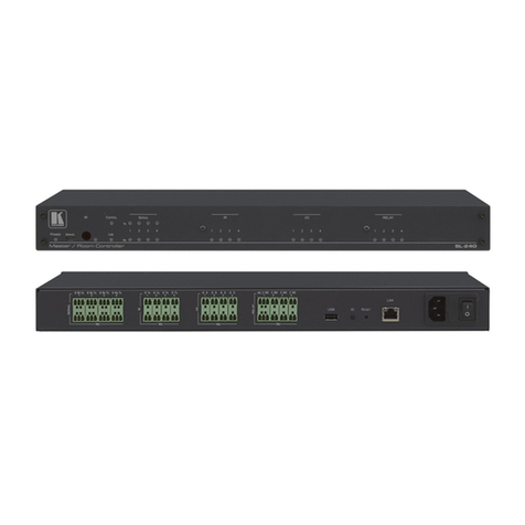
Kramer SL-12 User manual
Other Kramer Controllers manuals
Kramer
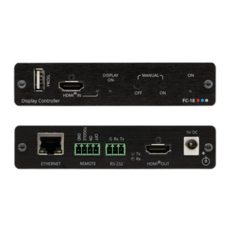
Kramer FC-18 User manual
Kramer
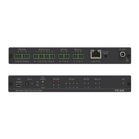
Kramer FC-28 User manual
Kramer
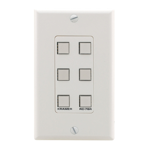
Kramer RC-76R User manual
Kramer
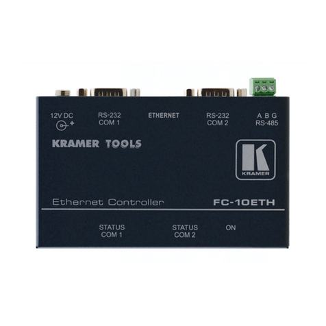
Kramer FC-10ETH User manual
Kramer
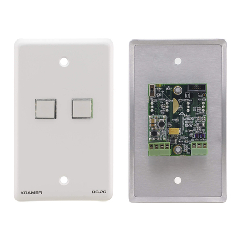
Kramer RC-2C User manual
Kramer
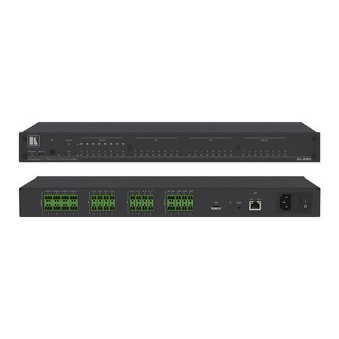
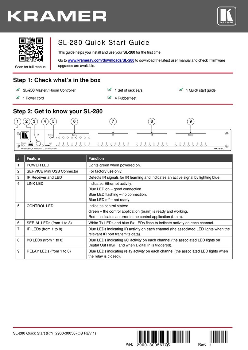
Kramer SL-280 User manual
Kramer
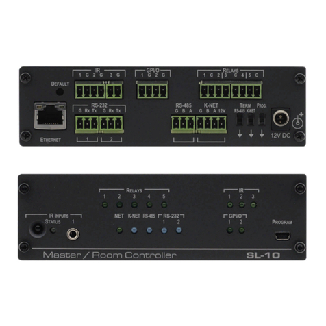
Kramer SL-10 User manual
Kramer
Kramer SL-280 User manual
Kramer
Kramer SL-12 User manual
Kramer
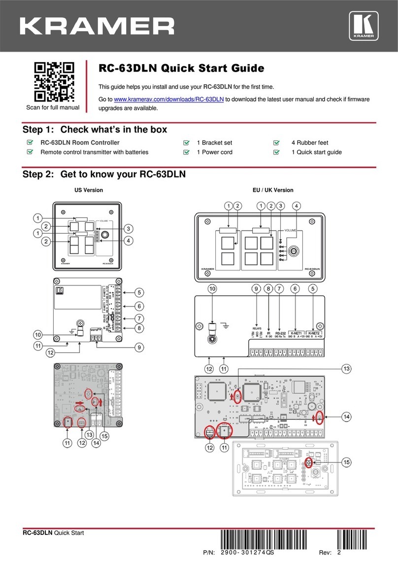
Kramer RC-63DLN User manual

Kramer
Kramer RC-13TC User manual
Kramer
Kramer RC-8RKL User manual
Kramer
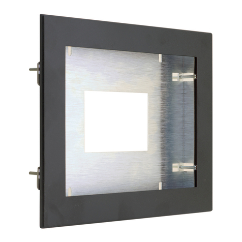
Kramer KT-107-INWL User manual
Kramer
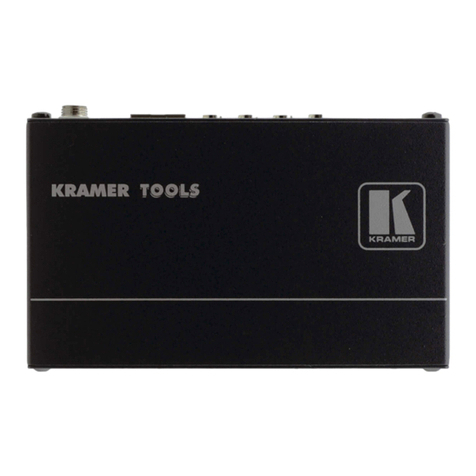
Kramer FC-26LA User manual
Kramer
Kramer RC-7RL User manual
Kramer
Kramer VA-4H User manual
Kramer
Kramer RC-7B User manual
Kramer
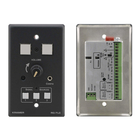
Kramer RC-7LC User manual
Kramer
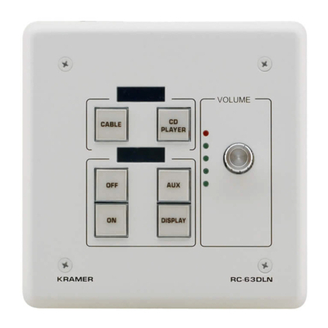
Kramer RC-63DLN User manual

Kramer
Kramer FC-10ETH User manual
Popular Controllers manuals by other brands

Digiplex
Digiplex DGP-848 Programming guide

YASKAWA
YASKAWA SGM series user manual

Sinope
Sinope Calypso RM3500ZB installation guide

Isimet
Isimet DLA Series Style 2 Installation, Operations, Start-up and Maintenance Instructions

LSIS
LSIS sv-ip5a user manual

Airflow
Airflow Uno hab Installation and operating instructions
