Shaver HD-12-H User manual
Hydraulic
Post Driver
Model HD-12-H
Shaver Manufacturing Company
103 South Washington Avenue, Graettinger, Iowa 51342
Phone: (712) 859-3293 — Fax: (712) 859-3294 — www.shavermfg.com
Safety
Operation
Maintenance
Repair
Troubleshooting
Parts
Operator’s Manual

Contents
Safety . . . . . . . . . . . . . . . . . . . . . . . . . . . . . . . 2
Safety Alert Symbols . . . . . . . . . . . . . . . . . . 3
Safety Icon Nomenclature . . . . . . . . . . . . . . 3
Safety Warnings . . . . . . . . . . . . . . . . . . . . . . . 4
General Safety . . . . . . . . . . . . . . . . . . . . . . . 4
Hazard Avoidance . . . . . . . . . . . . . . . . . . . . 4
Hydraulic Hoses . . . . . . . . . . . . . . . . . . . . . 5
Introduction . . . . . . . . . . . . . . . . . . . . . . . . . . 6
Product Information . . . . . . . . . . . . . . . . . . . 6
Specifications. . . . . . . . . . . . . . . . . . . . . . . . . 6
Assembly Procedure . . . . . . . . . . . . . . . . . . . 7
Recommended Tools . . . . . . . . . . . . . . . . . . 7
Unpacking . . . . . . . . . . . . . . . . . . . . . . . . . . 8
Assembly . . . . . . . . . . . . . . . . . . . . . . . . . . . 8
Main Carriage Channel . . . . . . . . . . . . . . . 9
Stabilizer Legs . . . . . . . . . . . . . . . . . . . . . 10
Base Plate . . . . . . . . . . . . . . . . . . . . . . . . 10
Hydraulic Valve . . . . . . . . . . . . . . . . . . . . 13
Safety Stop Adjustment . . . . . . . . . . . . . . 16
Rubber Debris Guard . . . . . . . . . . . . . . . 17
Safety Arm . . . . . . . . . . . . . . . . . . . . . . . . 18
Document Storage Tube . . . . . . . . . . . . . 21
Post Driver Operation . . . . . . . . . . . . . . . . . 21
Operational Safety Tips . . . . . . . . . . . . . . . 21
Operating Instructions . . . . . . . . . . . . . . . . 22
Mounting . . . . . . . . . . . . . . . . . . . . . . . . . 22
Preparing to Drive a Post. . . . . . . . . . . . . 23
Driving a Post. . . . . . . . . . . . . . . . . . . . . . 24
Dismounting Post Driver . . . . . . . . . . . . . 28
Troubleshooting . . . . . . . . . . . . . . . . . . . . . . 29
Storage. . . . . . . . . . . . . . . . . . . . . . . . . . . . . 29
Service Procedures . . . . . . . . . . . . . . . . . . . 30
Three-Point Hitch/Post Driver Assembly . . 30
Main Carriage Channel Disassembly . . . . 31
Drive Cylinder Seal Replacement . . . . . . . 34
Main Carriage Channel Assembly. . . . . . . 36
Forward and Side Tilt Cylinder
Maintenance . . . . . . . . . . . . . . . . . . . . . . . 40
Cylinder Disassembly . . . . . . . . . . . . . . . 40
Cylinder Assembly. . . . . . . . . . . . . . . . . . 41
Three-Point Hitch/Post Driver Assembly . . 43
Service Parts . . . . . . . . . . . . . . . . . . . . . . . . 44
Driver Assembly. . . . . . . . . . . . . . . . . . . . . 44
Hydraulic Base Plate Assembly . . . . . . . . 46
Three-Point Hitch Assembly . . . . . . . . . . . 48
Hydraulic Hoses . . . . . . . . . . . . . . . . . . . . 48
Safety Arm Assembly . . . . . . . . . . . . . . . . 48
Replacement Decals . . . . . . . . . . . . . . . . . 49
Document Storage Tube . . . . . . . . . . . . . . 49
Hydraulic Control Valve . . . . . . . . . . . . . . . 50
Drive Cylinder Assembly . . . . . . . . . . . . . . 51
Expanded View of Safety Lever
Assembly . . . . . . . . . . . . . . . . . . . . . . . . . 51
Tilt Cylinder Assembly . . . . . . . . . . . . . . . . 52
Limited Warranty . . . . . . . . . . . . . . . . . . . . . 53
Warranty Card . . . . . . . . . . . . . . . . . . . . . . . 54
Safety
Most work related accidents are caused by
failure to observe basic safety rules or
precautions. An accident can often be
avoided by recognizing potentially hazardous
situations before an accident occurs. As you
assemble and operate the Shaver Post Driver,
you must be alert to potential hazards. You
should also have the necessary training, skills,
and tools to perform this assembly procedure.
Improper operation and maintenance of this
implement could result in a dangerous
situation that could cause injury or death.
Do not assemble, operate, or maintain
the Shaver Post Driver until you read and
understand the information contained in
this manual.
Safety precautions and warnings are
provided in this manual and on the
product. If these hazard warnings are
not heeded, bodily injury or death could
occur to you or to other persons.
2
Shaver Manufacturing Company cannot
anticipate every possible circumstance that
might involve a potential hazard. The
warnings in this supplement and on the
product are, therefore, not all-inclusive. If a
method of operation, not specifically
recommended by Shaver Manufacturing
Company is used, you must satisfy yourself
that it is safe for you and for others. You
should also ensure that the implement will
not be damaged or be made unsafe by the
methods that you choose.
The information, specifications, and illustrations
in this supplement are based on the
information that was available at the time this
material was written and can change at any
time.
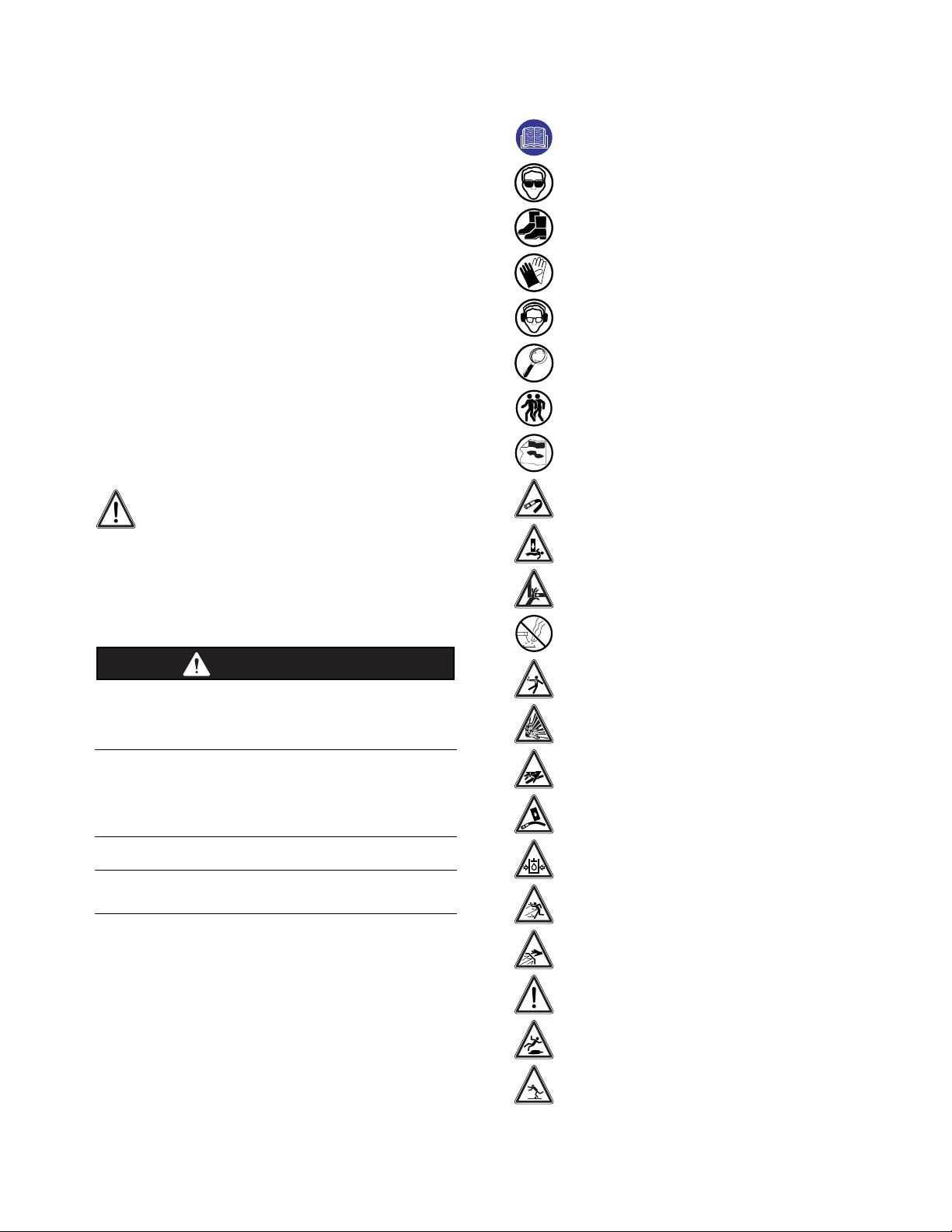
Safety Alert Symbols
TThheesafety alert symbol means
Attention! Become Alert! Your Safety
is Involved.
Hazards are identified by the “Safety Alert
Symbol” and are followed by the signal word
“WARNING”.
WARNING: Indicates a potentially hazardous
situation which, if not avoided, could result in
death or serious injury.
Potential damage situations are identified by the
signal words “IMPORTANT NOTICE”.
IMPORTANT NOTICE
Indicates that equipment or property damage
can result if instructions are not followed.
Safety Icon Nomenclature
Read the manual
Eye protection
Foot protection
Hand protection
Hearing protection
Inspect equipment
Two person operation
Warning decal alert
Bending hazard (hydraulic hose)
Crushing hazard
Crushing hazard (hand)
Do not weld
Electrocution hazard
Explosion hazard
High-pressure fluid hazard
Impact hazard (hydraulic hose)
Pressurized fluid
Projectile hazard (body)
Protective guards
Safety alert symbol
Slipping hazard
Tripping hazard
N
I
NG
AR
WARNING
3

44
Safety Warnings
General Safety
To avoid personal injury or death,
carefully read and understand all
instructions before attempting to
assemble and/or operate the Post
Driver. Do not operate or work on equipment
unless you read and understand the
instructions and warnings in this and all
other applicable manuals. Contact Shaver
Manufacturing Company. if any of the
instructions provided are unclear or not
understood. Proper care is your
responsibility. Always follow all State and
Federal health and safety laws and/or local
regulations.
To help prevent personal
injury, protective
equipment must be worn
during Post Driver
assembly, operation, and
maintenance. Personal
protective equipment
should include, but not
be limited to, safety glasses, hearing
protection, protective gloves, and steel toe
footwear.
Personal injury can result
from slips or falls. DO NOT
leave tools or parts laying
around the work area, and
clean up all spilled fluids immediately.
Hazard Avoidance
Inspect this equipment before each
use. Make sure all hardware is
tight. Always replace worn or
damaged parts before use.
To avoid personal injury or death,
do not operate the Post Driver by
yourself. Always have another
person to control the machine or
power source.
Make sure all decals are securely
attached to the Post Driver and are
legible at all times. Always read
and understand all decals before
working on or operating the Post Driver.
Make sure all lock-pins
and transport supports
are secured in place
before transporting or
storing the Post Driver..While transporting,
never ride on or permit others to ride on the
Post Driver..
Improper operating
procedures can create risk
for the operator and
bystanders. DO NOT use the
Post Driver before making sure no one will be
endangered.
To prevent personal
injury or death, be aware
of overhead electrical
lines when operating the
Post Driver. Electrocution can occur even
without direct contact with overhead power
lines. Proceed cautiously around electrical
lines and utility poles.
To prevent personal injury
or death, always check for
underground utilities,
such as electrical wires,
gas lines, and water pipes, before driving
posts. Contact local utility companies for
information on locating underground
utilities.
To avoid serious injury or
death, do not operate the
Post Driver on steep
slopes, as this can cause
a roll over.
To avoid personal injury,
always stand 45 degrees
to the right of the post
being driven while
operating the Post Driver.
N
I
NG
AR
WARNING
WARNING
WARNING

5
Potential pinch points.
Keep hands clear of Post
Driver while operating.
Never place hand(s) on
top of a post when inserting it into
the Post Driver. Always close the safety arm
before driving the post.
To avoid personal injury
do not attempt to clean,
adjust, or lubricate the
Post Driver while it is in
motion.
The rubber debris guard helps
shield the operator from flying
debris that may be generated
during post driving. To avoid
personal injury, make sure the rubber debris
guard is securely attached to the Post Driver
before driving posts.
To avoid personal injury or death,
do not modify the Post Driver by
welding, drilling, or grinding. Do
not expose to extreme heat, such
as from a torch.
The main carriage channel
assembly is tall and heavy. To
avoid tip over, resulting in serious
injury or death, leave the overhead
lifting device attached to the main carriage
channel while assembling components.
The safety arm is spring loaded. To
avoid serious injury or death, the
safety arm must be installed after
the Post Driver has been mounted
on a machine, or the freestanding Post
Driver has been secured to prevent tipping.
Hydraulic Hoses
Avoid damaging hydraulic hoses.
Avoid sharp bends and kinks when
routing hydraulic hoses. Sharp
bends and kinks can internally
damage the hose, leading to premature hose
failure, resulting in personal injury.
Do not drop heavy objects on
hoses. A sharp impact may cause
internal damage to the hose.
Applying pressure to a damaged
hose may cause it to rupture, resulting in
personal injury.
Mismatched couplings
and hoses can cause the
coupling to violently
disconnect from the hose
when placed under pressure; separating
with sudden, extreme force which can result
in property damage, personal injury, or
death.
Replace a hose if any of the following
conditions are present:
- End fittings that are damaged or leaking
- Outer coverings that are chafed or cut
- Wire shields that are exposed
- Outer coverings that are ballooning
- Flexible part of the hoses that are kinked
- End fittings that are displaced
Pressure can be trapped
in a hydraulic system.
Trapped pressure can
cause sudden movement
of an attachment. Use caution when
disconnecting hydraulic lines or fittings.
High-pressure oil that is released can cause
a hose to move violently while spraying oil.
Escaping high-pressure fluid can
penetrate the skin, causing serious
injury. Relieve pressure before
unhooking hoses. Check/tighten
all connections before activating hydraulics.
Never use your hand to check for leaks.
WARNING
WARNING
WARNING

6
Introduction
The Shaver Manufacturing Company would
like to congratulate you on your purchase of
the Shaver Hydraulic Post Driver. You have
selected the best Post Driver in its class. The
clean design and uncomplicated working
principle have made Shaver the largest selling
Post Driver in the country.
The Shaver HD-12-H (hydraulic tilt adjustment)
Hydraulic Post Driver is a durable piece of
equipment that, with regular maintenance, will
provide many years of service.
This manual provides information regarding
assembly, operation, and maintenance. It is
important to read and become familiar with
this manual before assembling or operating
the Shaver Hydraulic Post Driver.
NOTE: For other valuable information on farm
equipment operation and safety, refer to the
following resources.
•Farm Equipment Manufacturers
Association (FEMA)
http://www.farmequip.org/home
•National Ag Safety Database
http://www.cdc.gov/nasd
Product Information
Record Shaver product information here. The
model number and serial number are found on
the metal tag attached to the drive ram.
Model Number
Serial Number
Date Purchased
Dealer Name
Specifications
HD-12-H Post Driver
Approximate Length 1100 in (254 cm) collapsed
148 in (376 cm) extended
Approximate Width 244 in (111.8 cm)
Approximate Depth 238 in (96.5 cm)
Shipping Weight 975 lbs (442 kg)
Effective Weight of 1,100 lbs (499 kg)
Spring Powered
Driving Ram
Impact (at full stroke) 100,000 lbs (45,359 kg)
Main Carriage Channel
Tilt Front/Back 20°/20°
Tilt Side/Side 25°/25°
Guide Blocks 8 (4 per side)
Mounting options Tractor (rear) and skid steer
Three-Point Hitch Category II and III
Hydraulic Requirements 15 GPM at 2000 PSI
(45 LPM at 13,790 kPa)
Post Size
Maximum Width 10.875 in (27.6 cm)
Maximum Length 10 ft (3.0 m)
1Driving ram and main carriage channel. Overall length will
vary, depending on mounting position and tractor.
2With stabilizer legs attached to three point hitch weldment.
Assembly Procedure
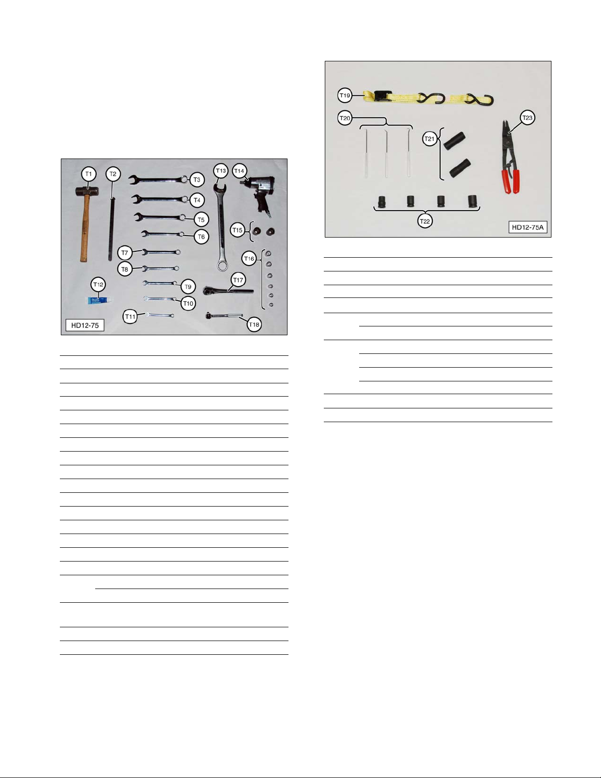
Recommended Tools
The basic tools needed to assemble and
maintain the HD-12-H Post Driver are shown
below. Additional specialized tools may be
required.
HD-12-H Recommended Tools
No. Description Qty
T1 Mallet or Hammer 1
T2 Straight Edge 1
T3 1-1/8 Inch Combination Wrench 1
T4 1-1/16 Inch Combination Wrench 1
T5 15/16 Inch Combination Wrench 1
T6 3/4 Inch Combination Wrench 1
T7 11/16 Inch Combination Wrench 1
T8 5/8 Inch Combination Wrench 1
T9 9/16 Inch Combination Wrench 1
T10 1/2 Inch Combination Wrench 1
T11 7/16 Inch Combination Wrench 1
T12 Paste-Type Thread Sealant AR
T13 1-1/2 Inch Combination Wrench 1
T14 1/2 Inch Drive Impact Gun 1
T15 1-1/2 Inch Impact Socket 1
1-1/16 Inch Impact Socket 1
T16 3/8 and/or 1/2 Inch Drive Socket Set
(9/16, 5/8, 11/16, 3/4, 15/16, 1 Inch ) AR
T17 1/2 Inch Drive Ratchet 1
T18 3/8 Inch Drive Ratchet 1
HD-12-H Recommended Tools (continued)
No. Description Qty
T19 Heavy-Duty Retaining Strap 1
T20 Heavy-Duty Seal Picks 1AR
T21 9/16 Inch Deepwell Impact Socket 1
1/2 Inch Deepwell Impact Socket 1
T22 9/16 Inch Impact Socket 1
5/8 Inch Impact Socket 1
11/16 Inch Impact Socket 1
3/4 Inch Impact Socket 1
T23 Heavy-Duty Snap Ring Pliers 11
— Soft Brass or Wood Drift 1(not shown) 1
1Required for cylinder seal replacement.
AR - As Required
7

Unpacking
Due to the size and weight of the
Post Driver, two people are required
for the assembly procedures.
The Post Driver is shipped in several sections:
the drive ram assembly, base plate assembly,
short channel bracket, hose and valve carton,
safety arm carton, and the tilt cylinder carton.
Before starting the unpacking
procedure, make sure the
overhead lifting device or material
handling device (forklift) has
adequate lifting capacity. Follow all safety
recommendations when unpacking the Post
Driver. Some components are heavy and
can cause serious injury or death if not
adequately supported during removal and
assembly.
For ease of assembly, unload the Post Driver
components in the area where they will be
assembled. Choose a large, hard surface
area that can safely support the weight of the
assembled Post Driver and is accessible by
the machine it will be mounted on.
Assembly
NOTE: Refer to the Service Parts section of
this manual for a photograph and description
of all the Post Driver parts.
The HD-12-H Post driver main carriage
channel has provisions for mounting the short
channel bracket in various positions. The
HD-12-H is shipped with the short channel
bracket bolts installed in the middle (most
common) mounting position. If an optional
mounting position is used, the three point hitch
weldment and stabilizer leg height will have to
be adjusted accordingly.
The Post Driver assembly procedure consists
of the following subsections:
1.Main Carriage Channel
2.Stabilizer Legs (optional)
3.Base Plate
4.Hydraulic Valve
5.Safety Stop Adjustment
6.Rubber Debris Guard
7.Safety Arm
8.Document Storage Tube
WARNING
WARNING
8

Main Carriage Channel
1.With road lock pin (B8) installed in lower
hole of drive ram (A1), use a suitable
overhead lifting device to raise (stand up)
main carriage channel (B1).
(A1) Drive Ram. (B1) Main Carriage Channel.
(B8) Road Lock Pin.
The main carriage channel
assembly is tall and heavy. To
avoid tip over, resulting in serious
injury or death, leave the overhead
lifting device attached to the main carriage
channel while assembling components.
2.Remove 6 factory installed bolts (D3) and
6 lock washers (D4). Install short channel
bracket (D2) using the bolts and lock
washers. Tighten bolts completely.
(A1) Drive Ram. (D2) Short Channel Bracket. (D3) Bolt.
(D4) Lock Washer.
3.Remove road lock pin (B8) from lower hole
in drive ram (A1). Use the overhead lifting
device to help raise main carriage channel
(B1) and insert road lock pin (B8) in upper
hole (tool storage position) in drive ram
(A1). Install Lynch pin (B9), not shown, to
secure the road lock pin.
(A1) Drive Ram. (B1) Main Carriage Channel.
(B8) Road Lock Pin.
WARNING
9

Stabilizer Legs (optional)
1.Place three-point hitch weldment (K1)
upside down on the floor. Install stabilizer
leg brackets (K2), with stabilizer legs (K7)
installed, over the cross tube, as shown.
Tighten two leg bracket bolts (K3) to secure
the brackets to the cross tube.
(K1) Three-Point Hitch Weldment. (K2) Leg Bracket.
(K3) Leg Bracket Bolt. (K7) Stabilizer Leg.
2.If the short channel bracket was mounted
at the most common center position in
Step 2, set stabilizer leg (K7) height at 8”
(20.3 cm) measured from three-point hitch
weldment (K1) cross tube to the stabilizer
leg base plate, as shown. Tighten the
stabilizer leg lock bolts.
(K1) Three-Point Hitch Weldment. (K2) Leg Bracket.
(K7) Stabilizer Leg.
NOTE: If a set of six threaded holes other
than the center set, were used to mount short
channel bracket (D2), the height of the legs
will need to be adjusted accordingly.
3.Turn over three-point hitch weldment (K1)
and set it on stabilizer leg (K7) base plates,
as shown.
(K1) Three-Point Hitch Weldment. (K7) Stabilizer Legs.
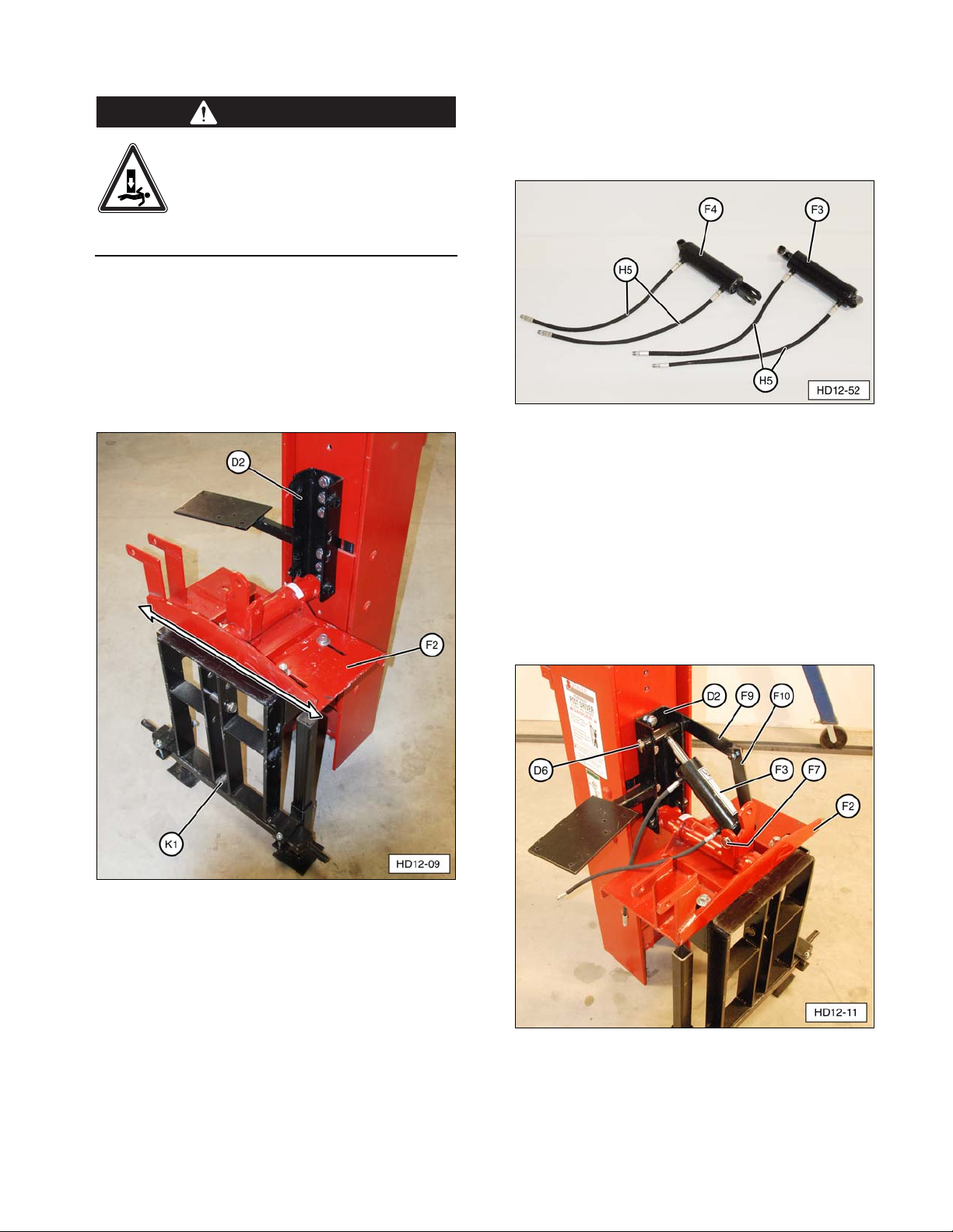
Base Plate
1.Remove the four carriage bolts, washers,
and nuts from base plate (F2). Save
hardware for reuse.
(F2) Base Plate.
10
The main carriage channel
assembly is tall and heavy. To
avoid tip over, resulting in serious
injury or death, leave the overhead
lifting device attached to the main carriage
channel while assembling components.
2.With three point hitch weldment (K1)
positioned in front of short channel bracket
(D2), install base plate (F2) as shown.
Install the bolts, washers, lockwashers, and
nuts removed in Step 1. Center the base
plate on the three-point hitch weldment and
tighten the hardware securely.
(D2) Short Channel Bracket. (F2) Base Plate.
(K1) Three-Point Hitch Weldment.
3.Install four hose assemblies (H5) on tilt
cylinders (F3, F4) using paste-type thread
sealant (T12) on fittings. Tighten the hose
fittings securely.
(F3) Forward Tilt Cylinder. (F4) Side Tilt Cylinder.
(H5) Hydraulic Hose Assembly.
4.Install forward tilt cylinder (F3) on base
plate (F2), along with safety lever (F9, F10),
as shown. Attach with long cylinder
mounting pin (F7) and channel mounting
pin (D6).
NOTE: Secure long cylinder mounting pin (F7)
and channel mounting pin (D6) with Lynch
pins (D7) (included).
(D2) Short Channel Bracket. (D6) Channel Mounting Pin.
(F2) Base Plate. (F3) Forward Tilt Cylinder.
(F7) Long Cylinder Mounting Pin. (F9, F10) Safety Lever.
WARNING
11

5.Install side tilt cylinder (F4) on base plate
(F2), as shown. Attach with long cylinder
mounting pin (F7) and short cylinder
mounting pin (F8).
NOTE: Secure long cylinder mounting pin (F7)
and short cylinder mounting pin (F8) with
Lynch pins (D7) (included).
(F2) Base Plate. (F4) Side Tilt Cylinder. (F7) Long
Cylinder Mounting Pin. (F8) Short Cylinder Mounting Pin.
6.Attach base plate (F2) to short channel
bracket (D2).
a. With the main carriage channel still
attached to an overhead lifting device,
use a suitable floor jack to support
three-point hitch weldment (K1).
(D2) Short Channel Bracket. (D6) Mounting Pin.
(F2) Base Plate. (K1) Three-Point Hitch Weldment.
(K7) Stabilizer Leg. (K8) Stabilizer Leg Lock Bolt.
12

b. Loosen stabilizer leg lock bolts (K8),
and adjust floor jack up or down to
align base plate (F2) pivot pin hole with
short channel bracket (D2) lower
mounting hole.
c. Install lower channel mounting pin (D6)
and secure with Lynch pins. Tighten
two stabilizer leg lock bolts (K8) and
remove the floor jack.
(D2) Hydraulic Short Channel Bracket.
(D6) Mounting Pin. (K8) Stabilizer Leg Lock Bolts.
Hydraulic Valve
IMPORTANT NOTICE
Hydraulic system fittings that require a thread
sealant, must be installed with a paste-type
sealer only. Do not use a tape-type sealer such
as Teflon Tape, as this can contaminate the
system and voids the valve warranty.
1. Assemble the hydraulic control valve.
a. Remove the plastic plugs from
hydraulic control valve (H1). Apply
paste-type thread sealant (T12) to pipe
threads. Install hydraulic fittings (G16,
G18, G19, G21), and four tilt cylinder
hose fittings (H3). Refer to the
photographs for correct fitting
placement and orientation.
(H1) Hydraulic Control Valve.
(G16) Swivel Fitting:
3/4” O-Ring Male to 1” Female NPT.
(G19) 90° Swivel Fitting:
1-1/16” O-Ring Male to 1/2” Female.
(G21) 90° Swivel Fitting:
3/4” Male to 1” NPT Female with
Adapter Fitting:
1-1/16” O-Ring Male to 3/4” NPT Female.
(H3) 90° O-Ring Swivel Fitting (with restricter):
7/8” Male to 1/4” Female.
13
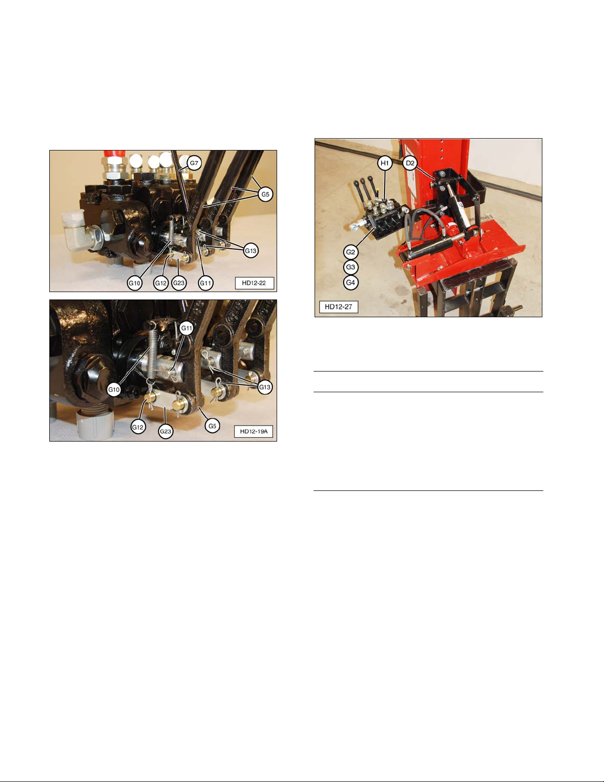
b. Assemble the control valve linkage.
Install levers (G5), control valve safety
lever (G7), return spring (G10), and
lever linkage (G11, G12, G23), as
shown. Secure with cotter pins (G13).
Refer to photographs for correct
linkage placement and orientation.
(H1) Hydraulic Control Valve Linkage.
(G5) Control Valve Levers. (G7) Control Valve Safety
Lever. (G10) Safety Lever Return Spring. (G11) Clevis
Pin. (G12) U-Link. (G13) Cotter Pin(s). (G23) Flat Link.
2. Install hydraulic valve (H1) on short
channel bracket (D2) using three
5/16-18 x 3” valve mounting bolts (G2),
washers (G3), and nuts (G4). Do not
over-tighten the hardware, which can warp
the valve body.
(D2) Short Channel Bracket. (G2) 5/16-18 x 3” Bolt.
(G3) 5/16” Washer. (G4) 5/16-18 Nut.
(H1) Hydraulic Control Valve.
IMPORTANT NOTICE
The hydraulic valve and cylinder(s) can be
damaged by contamination (dirt and debris)
from the oil in the tractor or power source.
Ensure the oil is clean and properly filtered
before connecting the Post Driver to a hydraulic
power source. Failure to follow oil cleanliness
standards voids the Shaver Post Driver
warranty.
14

3. Attach the three main hydraulic hoses.
(G15) Valve to Drive Ram Hose. (G17) Pressure Supply
Hose. (G20) Return Hose.
a. Apply paste-type thread sealant (T12)
to the pipe thread hose fittings and
install drive cylinder hose (G15) (1” I.D.
x 35”) between hydraulic control valve
(H1) and drive cylinder assembly (C1).
Tighten the hose fittings securely.
(C1) Drive Cylinder Assembly. (G15) Valve to Drive Ram
Hose. (H1) Hydraulic Control Valve.
b. Connect the threaded fitting on
pressure hose (G17) (1/2” x 120”) to
hydraulic control valve (H1) swivel
fitting.
c. Connect the threaded fitting on return
hose (G20) (1” x 120”) to hydraulic
control valve (H1) swivel fitting.
(G17) Pressure Hose. (G20) Return Hose.
(H1) Hydraulic Control Valve.
NOTE: The owner/operator must supply
suitable hydraulic quick disconnect fittings for
connecting pressure supply hose (G17) and
return hose (G20) to the tractor or power
supply hydraulic system.
15

IMPORTANT NOTICE
If the tilt cylinder hoses are attached differently
than shown, the control of the drive ram will not
be as described in this manual.
d. Attach two forward tilt cylinder hoses
(H5) between forward tilt cylinder (F3)
and hydraulic control valve (H1), as
shown.
(A) Back Tilt Hose Connections. (B) Forward Tilt Hose
Connections. (F3) Forward Tilt Cylinder. (H1) Hydraulic
Control Valve. (H5) Tilt Cylinder Hoses.
e. Attach two side tilt cylinder hoses (H5)
between side tilt cylinder (F4) and
hydraulic control valve (H1), as shown.
(A) Right Tilt Hose Connections. (B) Left Tilt Hose
Connections. (F4) Side Tilt Cylinder. (H1) Hydraulic
Control Valve. (H5) Tilt Cylinder Hose.
Safety Stop Adjustment
To avoid serious injury, inspect the
control valve safety stop before
using the Post Driver the first time
and before each daily use. Adjust
the safety stop as needed, per the following
procedure. Make sure all control valve
hardware is tight. Always replace worn or
damaged parts before use.
The control valve safety stop prevents
unintentional activation of the Post Driver
control valve and must be functional at all
times.
NOTE: If the Post Driver is operational, before
adjusting the safety stop, make sure the
machine/power source is OFF, parking brake
is set, road lock pin is installed, and all
hydraulic pressure is released (zero pressure).
1. Attempt to push main hydraulic control
valve lever (G5) forward (away from
operator) wwiitthhoouuttsqueezing (pulling) yellow
tipped control valve safety lever (G7).
(G5) Main Hydraulic Control Valve Lever. (G7) Control
Valve Safety Lever.
2. If main hydraulic control valve lever (G5)
CAN move forward more than 1/4”, the
safety stop must be adjusted.
WARNING
16

17
3. To adjust the safety stop, do the following:
a. Squeeze the control valve lever and the
control valve safety lever together to
expose the safety lever stop setscrew.
b. Insert a 1/8” Allen wrench and adjust
the setscrew outward
(counterclockwise) slightly. Remove
the Allen wrench and repeat Step 1.
Adjust the Safety Stop Setscrew.
c. If necessary, repeat Step 3a and
Step 3b until the setscrew prevents
more than 1/4” of forward movement of
the control valve lever.
NOTE: Do not “over adjust” the setscrew.
Make sure the setscrew easily falls into place
behind the lip on the control valve when it is
released quickly (1/8” gap at the setscrew).
1/8” Gap Between Setscrew and Valve Body.
Rubber Debris Guard
1. Locate rubber debris guard (A4), guard
mounting strap bracket (A5), and bag
containing hardware and caution tag
(A6, A7, A8, and A9).
(A4) Rubber Debris Guard. (A5) Guard Mounting Strap
Bracket. (A6) Caution Tag. (A7) Bolt. (A8) Lock Washer.
(A9) Nut.
2. Attach the rubber debris guard, mounting
strap, and caution tag on drive ram (A1)
with guard mounting bolts, lock washers
and nuts, as shown.
NOTE: To avoid damage to the rubber debris
guard, do not over-tighten the mounting
hardware.
(A1) Drive Ram.
Safety Arm
The safety arm is spring loaded. To
avoid serious injury or death, the
safety arm must be installed after
the Post Driver has been mounted
on a machine, or the freestanding Post
Driver has been secured to prevent tipping.
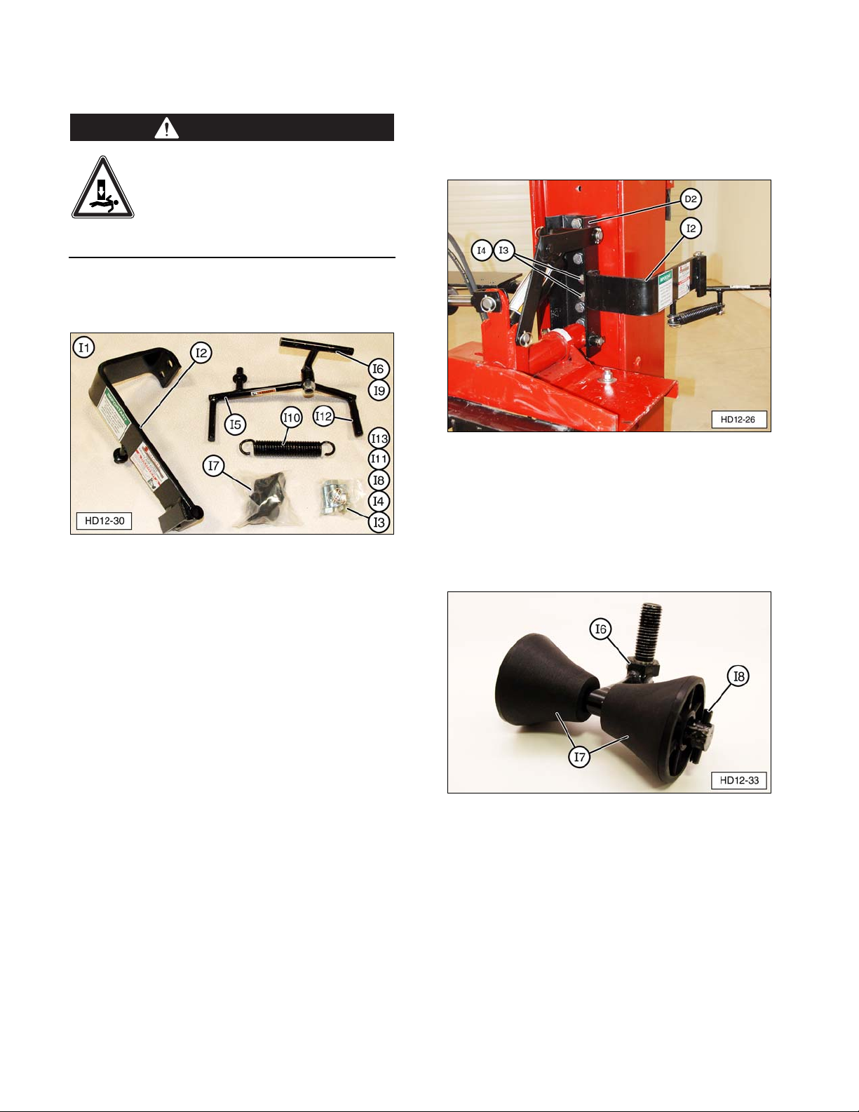
1. Locate the safety arm assembly parts and
hardware.
(I2) Safety Arm Frame. (I3) Frame Mounting Bolt.
(I4) Self Locking Nut. (I5) Swing Arm Handle.
(I6) Roller Bracket. (I7) Rollers. (I8) Roller Retainer Roll
Pin. (I9) Roller Bracket Nut. (I10) Latch Spring.
(I11) Spring Retainer Flat Washer. (I12) Swing Arm
Handle Cover. (I13) Lynch Pin.
2. Attach safety arm frame (I2) to outside of
short channel bracket (D2) with two
3/4-10 x 2” frame mounting bolts (I3) and
self locking nuts (I4), as shown. Tighten
the nuts securely.
(D2) Hydraulic Short Channel Bracket.
(I2) Safety Arm Frame. (I3) Frame Mounting Bolt.
(I4) Self Locking Nut.
3. Assemble rollers (I7) onto roller bracket (I6)
and use hammer (T1) to install two roller
retainer roll pins (I8), as shown.
(I6) Roller Bracket. (I7) Roller.
(I8) Roller Retainer Roll Pin.
WARNING
18

19
4. Apply a light film of a good quality grease
to the pivot shaft and attach roller bracket
(I6) to swing arm handle (I5) with roller
bracket nut (I9). Tighten the nut until
seated and then loosen 1/4 to 1/2 turn.
NOTE: Roller bracket (I6) must swivel freely
on swing arm handle (I5).
(I5) Swing Arm Handle. (I6) Roller Bracket.
(I9) Roller Bracket Nut.
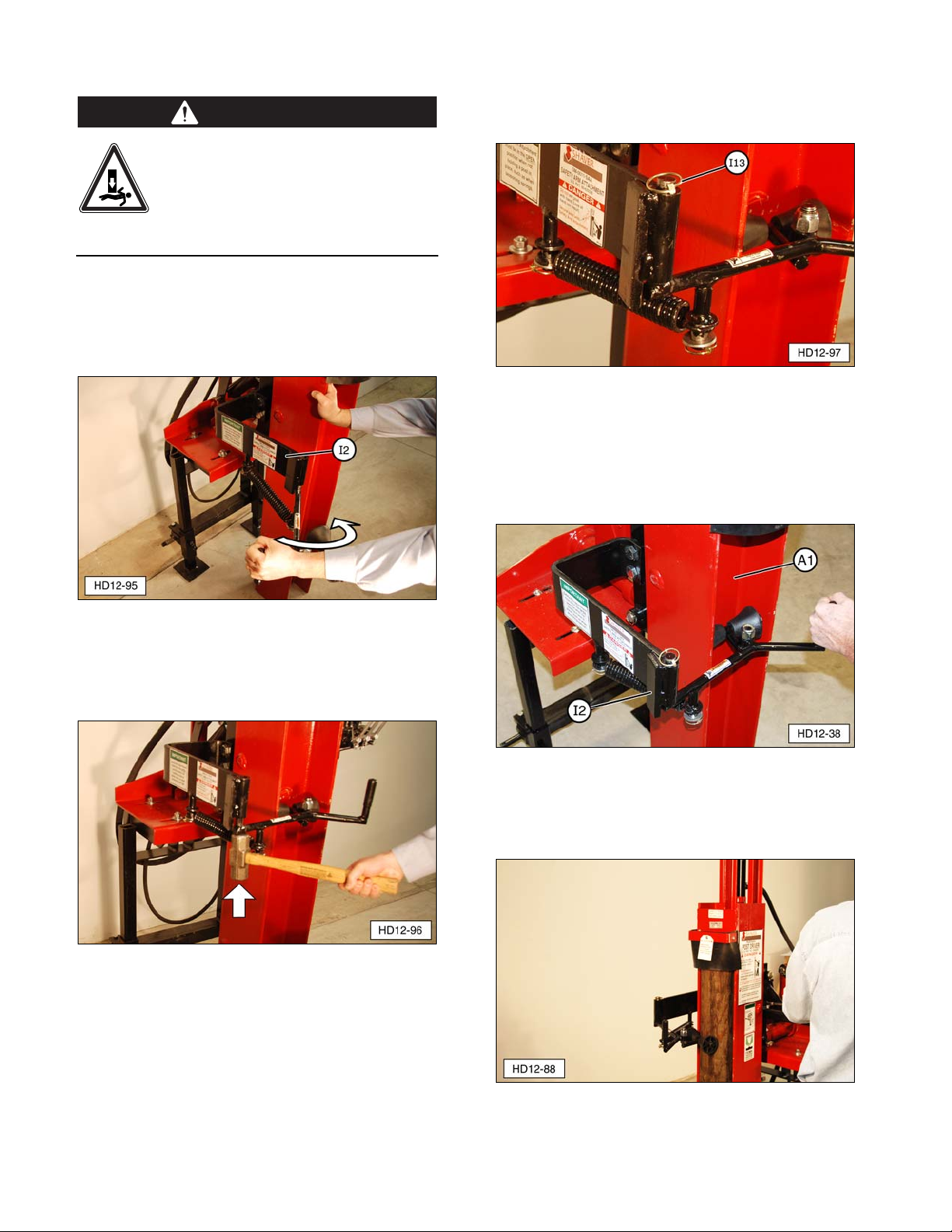
5. Attach one end of latch spring (I10) to
swing arm handle (I5), as shown. Secure
with spring retainer flat washer (I11) and
Lynch pin (I13).
(I5) Swing Arm Handle. (I10) Latch Spring.
(I11) Spring Retainer Flat Washer. (I13) Lynch Pin.
6. Install the swing arm assembly.
a. Apply a light film of a good quality
grease to the pivot shaft on swing arm
handle (I5).
b. Start the pivot shaft into the main
bracket tube, as shown. Slide the open
spring eye over the main bracket
anchor rod.
NOTE: Swing arm handle (I5) will be below
safety arm frame (I2) bracket stop at this
point.
c. Secure the spring with flat washer (I11)
and Lynch pin (I13).
(I11) Flat Washer. (I13) Lynch Pin.
19
The safety arm is spring loaded. To
avoid serious injury or death, the
safety arm must be installed after
the Post Driver has been mounted
on a machine, or the freestanding Post
Driver has been secured to prevent tipping.
7. Pull the swing arm handle around toward
the Post Driver I-beam until the swing arm
clears (swings past) safety arm frame (I2)
bracket stop.
(I2) Safety Arm Frame.
8. Tap the swing arm shaft up through the
safety arm frame tube.
9. Install Lynch pin (I13) to secure the swing
arm to the safety arm frame.
(I13) Lynch Pin.
10. Verify the swing arm handle opens against
safety arm frame (I2) stop bracket and
closes against back wall of drive ram (A1)
I-beam.
(A1) Drive Ram. (I2) Safety Arm Frame.
NOTE: When driving a fence post, the swing
arm rollers must contact and hold the fence
post in position, as shown.
WARNING
2020
Table of contents


