Shengyi CMT03P Owner's manual

~- 1 - ~
CMT03P Technical Instruction
(English Version)
Product Name: Mid Motor Drive Unit
Product Model: CMT03P (Standard
Configuration)

~- 2 - ~
Important Notice
•Please read this manual and the attached installation manual carefully. If you are
not clear about any part of the information in this manual, please do not install it.
Please consult the sales office.
•Please contact the dealer for product information not described in this manual.
•Do not disassemble or modify the product except the information stated in this
user manual.
•Distributors must abide by the relevant laws and regulations of their countries
and regions.
•Please follow the instructions given in the manual to install this product and use it
correctly.
•Loose, damaged and improper adjustment of bolts and nuts may lead to sudden
fall and serious injury.
•Be sure to let users know the following:
Before riding, please check whether the wheels are fixed. When riding, don't be
distracted by the instrument and fall off.
•Please be fully familiar with how to start the electric bicycle before riding it.
Otherwise, it may accidentally start the electric bicycle and cause an accident.
When riding at night, please make sure to turn on the headlights.
•Please unplug the battery before wiring or installing parts of the bicycle to
prevent possible electric shock.
•Please use this product according to the instructions. Do not let people and
children who have no operating experience, physical, sensory or mental diseases
use this product, and do not let children play around this product.
•Please consult the dealer for information about product installation and
adjustment software update (do not modify the software system without
permission, which may easily lead to system failure). If there is any malfunction or
problem, please consult the nearest dealer.
•This product is designed to be waterproof and can be driven in rainy days, but do
not soak it in water, and do not use high-pressure water gun to clean it. As a result,
the water immersion will lead to failure or rust.
•Please use this product with care, and do not apply strong impact.
•If you have any questions about the maintenance and use of the product, please
consult the dealer at the place of purchase.
•Normal use of this product will cause natural wear and aging.

~- 3 - ~
Catalogue
1. Mid motor
2. Attachment
3. Assembly method
4. Matters needing attention and fault analysis
5. Packing list
6. Packaging method

~- 4 - ~
1. Mid motor drive unit
★It can meet the needs of bicycle installation and is convenient to install;
★The central drive unit has a high degree of modular design, which is
convenient for motor maintenance;
★The middle drive unit adopts half-package design, which is convenient for
customers to customize;
★The center drive unit has double clutches;
★The center drive unit is controlled by torque and has a built-in controller;
★Large starting torque is more conducive to climbing;
★High efficiency, low power consumption and long cruising range.
1.1 Material and waterproof grade
Shell materials and surface treatment
Internal aluminum shell: die-cast aluminum surface is coated by electrophoresis
with matt black;
Outer plastic shell: the surface of the plastic shell is sprayed with matt black and
silver paint.
Protection grade: IP65;;
Environment: temperature:-20℃~ 55℃atmospheric pressure: altitude ≤1000
m.
Relative humidity: ≤90% at 25℃

~- 5 - ~
1.2 Main technical parameters
Model
CMT03P36
CMT03P48
Rated power
350W@105RPM
450W@105RPM
Maximum input
power
500W(T<7min); max:
640W
650W(T<7min);max:
860W
Rated voltage
36V
48V
Maximum current
limit
18A
18A
Maximum torque
120Nm@25RPM
120Nm@25RPM
Maximum speed
115RPM
115RPM
Maximum efficiency
≥80%
≥80%
2. Attachment
2.1 Instrument
2.1.1 Instrument name
Medium color TFT LCD instrument, model: APT 850C
LCD display description and key function description
Liquid crystal full display diagram:
Speed mode
Headlight indicator
Battery indicator
Gear indicator
Mileage mode
Mileage indicator
Speed display
Failure reminder
Braking reminder
Key function:

~- 6 - ~
2.1.2 Parameter setting
See 850C-ENS product specification -J-202106 billion.
2.2 Speed sensor
2.2.1 Product model
Model: SPL-10
2.2.2 Appearance
2.2.3 Product installation drawing

~- 7 - ~
Locking Torque (<1Nm)
2.2.4 Specific specifications
Parameter
Numerical value
Rated voltage
DC5V
Rated current
5mA
Pulse/cycle
one
Installation distance
3-10mm
Working temperature
-30~70℃
Waterproof grade
IPX7
Authentication
CE ROHS
2.3 Dental tray
2.3.1 Appearance of dental tray: (as shown in the figure)
2.3.2 Tooth plate model: 42T unilateral chain cover
2.3.3 Basic parameters of dental tray
Number of teeth: 42 teeth
Shape: concave, with circular pattern
Color: black

~- 8 - ~
2.4 Crank
2.4.1 Appearance of crank: (as shown in the figure)
2.4.2 Crank model: TS1-170AA
2.4.3 Basic parameters of crank:
Length: 170mm
Material: 6061
Color: black
* Note: The left and right cranks have different thread directions, and the left
crank is marked with "L"
The right crank is marked with "R"
2.5 Other accessories
Connection Plate Hex Torx sunk socket M6X65 Hex Torx sunk screw M6X18
Plastic shell (a set of 4) hexagon socket pattern pan head screws M4X8
~- 9 - ~
3. Assembly method
3.1 System schematic diagram and wiring diagram

~- 10 - ~
3.1.1 System schematic diagram

~- 11 - ~
3.1.2 System wiring diagram

~- 12 - ~
3.2 Schematic diagram of loading
3.2.1 Threading
Penetrating the external speed sensing adapter, headlight adapter, instrument
adapter, rear light adapter and power adapter into the whole vehicle according to
the requirements of the whole vehicle;
Insert the above wires into the motor according to 3.1.2 System Wiring Diagram;
Arrange the line length and position;
3.2.2 Install the motor
Insert three hexagon socket countersunk screws M6X65 and three hexagon socket
countersunk screws M6*18 into the three holes of the frame connecting plate as shown
in the figure and lock them(locking torque: 8-10Nm);
()

~- 13 - ~
3.2.3 Install the plastic housing.
Fix the plastic shell to the motor;
Lock six M4X8 hexagon socket head screws as shown in the figure(locking
torque: <1Nm);
① ②
③
3.2.4 Install the tooth plate and lock the screw of the tooth plate.
Install the tooth disk assembly on the motor according to the spline groove
direction;
Tighten the nut (anti-tooth) of the tooth plate in the reverse direction(locking
torque: 20-24Nm);

~- 14 - ~
3.2.5 Install left and right cranks and lock crank screws.
Sleeve the crank on the central shaft (the included angle between the left and right
cranks is 180)(locking torque 30-35Nm);
Lock the crank screw as shown in the figure;
3.2.6 Install external speed sensor and magnetic steel.
See 2.2.3 Product Installation Diagram for installation requirements.

~- 15 - ~
4. Matters needing attention and fault analysis
4.1 Matters needing attention
It should be parked in a ventilated and dry warehouse. It should not be parked in a
damp, acid and alkali place, nor should it coexist with magnetic articles.
Each connector is plugged into place according to the arrow;
Liquid crystal avoids the impact of sharp objects;
It is recommended that the product should not be overloaded for a long time.
Products should avoid wading or soaking in water.
4.2 General fault analysis
serial
num
ber
Fault phenomenon
Possible causes of failure
debugging
one
The motor cannot be
mounted on the frame.
Welding deformation of frame
connecting plate
Reduce welding deformation
of frame.
2
Meter no display
Plug-in is not connected
properly.
Check all plug-ins and connect
Use non-standard instruments.
Use our standard instrument.
The battery runs out.
Charge as required
three
Meter kilometers are not
displayed.
The external speed sensor
plug-in is not connected
properly.
Check plug-in and connect
Magnetic steel is not installed
in place.
Check the position of
magnetic steel and install it.
four
Meter kilometer display is
abnormal.
Unreasonable magnetic steel
position distance
Adjust the position distance of
magnetic steel.
There is strong environmental
interference
Change the environment
five
The front/rear lights are
off.
The light control module is not
installed.
Install the light control module
Plug-in is not connected
properly.
Check all plug-ins and connect
The rated voltage of front/rear
lamps does not match.
Replace the front/rear lights
with the correct voltage.
six
No response when the
brake is cut off.
Plug-in is not connected
properly.
Check all plug-ins and connect

~- 16 - ~
Note: When the motor works without external force, it is normal for the crank to follow.
4.3 Other fault analysis and error codes
NO
error
code
Wrong definition
LED flashing
describe
1
0x00
normal
Flash once per second
--
2
0x10
overtension
Flash once
restorability
3
0x11
undervoltage
Flash twice
restorability
4
0x12
Motor speed
feedback failure (such
as motor stalling)
Flash 4 times
restorability
5
0x13
Overtemperatu
re
Flash 9 times
restorability
6
0x14
Voltage fault
Flash 10 times
beyond
retrieve
7
0x15
Abnormal output
Flash 11 times
beyond
retrieve
8
0x16
MCU fault
Flash 12 times
beyond
retrieve
9
0x17
Flying car
protection
Flash 13 times
beyond
retrieve
10
0x18
Pedal sensor failure
Flash 14 times
beyond
retrieve
11
0x19
Speed sensor
failure
Flash 15 times
beyond
retrieve
12
0x30
Communication
failure
The controller
can't
communicate
with the
instrument,
and the
instrument
sends a fault
code.
13
0x21
overflowing
overflowing
Flash 3 times
restorability
MOS tube
failure
Flash 6 times
beyond
retrieve
14
0x22
Turn the voltage
too high
Flash 8 times
restorability

~- 17 - ~
NO
error
code
Wrong definition
LED flashing
describe
15
0x23
Phase line fault
Flash 7 times
beyond
retrieve
16
0x24
Hall fault
Flash 5 times
restorability
17
0x25
Brake failure
restorability
note:
Recoverable-after the alarm, the EPAC drive system will detect it in real time. After the fault
disappears, the alarm will be relieved and normal operation will be achieved.
Unrecoverable-epac drive system can't work normally. Turn off the power and troubleshoot.
The display instrument can display error codes or error messages.
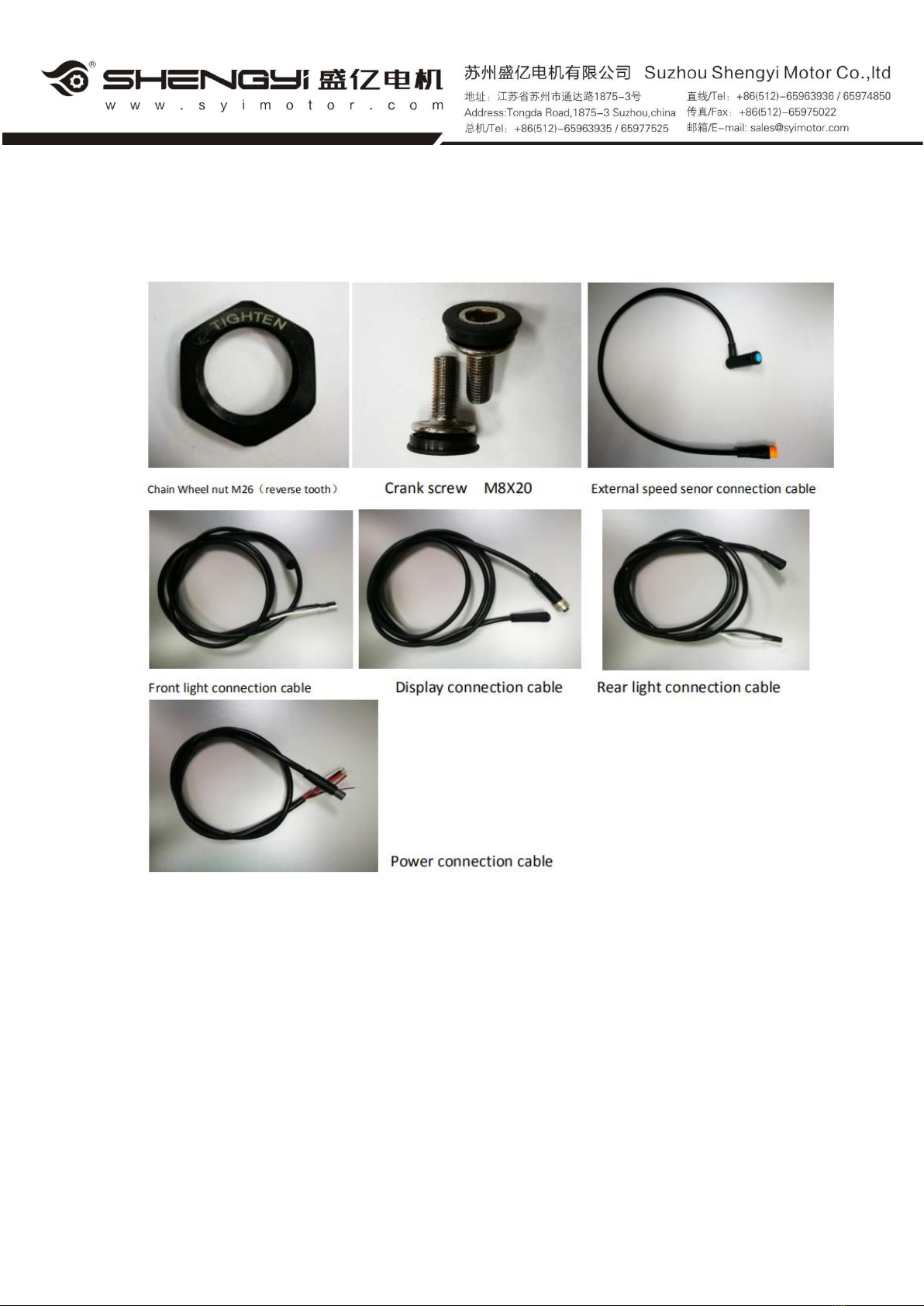
5. Packing list
1. 1 central drive unit
2. 1 instrument
3. 1 set of speed sensor (including magnetic steel)
4. 1 set of dental tray assembly
5. Left crank 1PCS
6. Right crank 1PCS
7. 1 set of plastic shell
8. Tooth disk nut M26 (anti-tooth) 1PCS
9. Crank screw M8X20 (used to install crank) 2PCS
10. Hexagon socket pattern pan head screw M4X8 (used to install plastic shell)
6PCS
1. Hexagon socket type countersunk head screw M6X65 (used to connect the
motor and the frame connecting plate) 3PCS
12. Hexagon socket countersunk head screw M6X18 (used to connect motor and
frame connecting plate) 3PCS
13. One external speed sensing adapter.
14. 1 headlamp adapter
15. 1 instrument adapter cable
16. 1 connector for rear light

~- 18 - ~
17. 1 power adapter cable
6. Packaging method
Wrap the motors in plastic film bags, and put 3 sets in one box;
Accessories are packaged separately from the motor; (Pay attention to counting
quantity);
* In addition, the connecting frame is shipped separately in advance, which is
convenient for welding the frame in advance and facilitating production arrangement.
Table of contents
Popular DC Drive manuals by other brands


DMG LUMIERE
DMG LUMIERE WDMX DRIVER user manual

GU
GU ELTRAL VA35 Assembly and operating instructions

Digga
Digga PDD-PD50 Service & repair manual

Shugart
Shugart SA1000 manual

Sumitomo Drive Technologies
Sumitomo Drive Technologies Invertek Drives Optidrive P2 manual

Danfoss
Danfoss VLT Brake Resistor MCE 101 Design guide