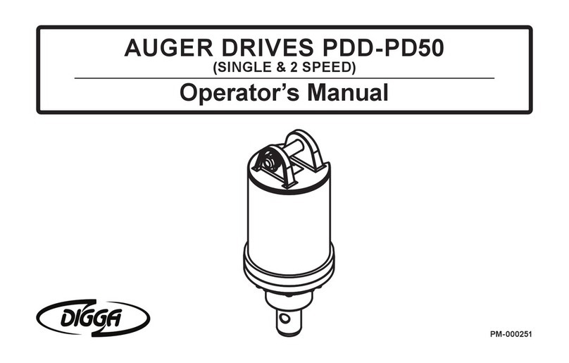
Digga PDD-PD50 Operating instructions

1
AUGER DRIVES
PDD - PD50
SERVICE & REPAIR MANUAL
PM-000100-D

2
PM-000100-D PDD - PD50 Service and Repair Manual - October 2017
SINGLE & DOUBLE PLANETARY AUGER DRIVES
This manual is intended to be used by persons with reasonably mechanical skills and understanding of mechanical components.
This manual will assist in the disassembly and assembly of the above model Planetary Auger Drives. Item numbers, indicated in pa-rentheses
throughout this manual, refer to the exploded parts breakdown drawing. Individual customer specications (mounting hood, output shaft etc.) may
vary from exploded drawing and standard part numbers shown. Contact Digga Australia for enquiries.
For any spare or replacement parts, contact Digga Service and Spares or a local Digga representative. For identication purposes always try to have
available the auger drive unit type and serial number. This information may be necessary for verication of any component part numbers. Component
part numbers and/or manufacturing gear set numbers may be stamped on individual parts. This information may also be helpful in identifying
replacement components.
CHANGING GEAR OIL
Change the gear oil after 6 months or 80 hours of moderate operation, then every 500 hours or 12 months whichever comes rst.
PD MODEL OIL CAPACITY (LITRE)
PDD (Post Aug 2013) 0.25
PDD (Pre Aug 2013) - PD5 0.550
PD6 - PD12 1.45
PD15 - PD22 2.85
PD25 - PD50 4.8
PREMIUM DRIVE UNIT RANGE (PDD-PD50 DRIVE UNITS)
Use quality extreme pressure gear oil
(EP ISO 320 GRADE - MINERAL OIL)
NOTE
It is also recommended that unit be partially disassembled to inspect gears and bearings at 2 year intervals. Oil changes must be performed by a
Authorised Service Agent. Please Contact Digga for your nearest service location.
MODERATE OPERATING CONDITIONS SEVERE OPERATING CONDITIONS*
FIRST OIL CHANGE Within 3 months OR initial 50 hours of use Within the rst 30 hours of use
2ND OIL CHANGE PLUS SUBSEQUENT OIL CHANGES After 500 hours or 12 months of use After 300 hours of use thereafter (Drive requires a major
stripdown, inspection and rebuild)
GEARBOX OIL:- - CASTROL ALPHASYN ISO SP 320 (MINERAL) OR EQUIVALENT
*SEVERE OPERATING CONDITIONS:- AMBIENT TEMPERATURES BELOW 0° (32°F) & ABOVE 40°C (104°F). WORKING IN HARD GROUND.
EXTENDED AND CONTINUOUS HOURS OF OPERATION.
THE GEARBOX OIL CAPACITY IS ENGRAVED ONTO THE SERIAL TAG LOCATED ON THE TOP OF THE HOOD.
Initial (Bed-in) oil change:
• The rst oil change must be carried out within the rst 50 hours of use under MODERATE OPERATING CONDITIONS.
Thereafter, every 500 hours.
• Change the gear oil after the rst 30 hours of SEVERE OPERATING CONDITIONS*. (i.e. severe ambient temperature conditions of +40°C or
below 0°C, when augering, screw piling or core barrelling in hard ground.) Thereafter, every 300 hours.

3
TABLE OF CONTENTS
LUBRICATION & MAINTENANCE............................................................................ 2
TABLE OF CONTENTS............................................................................................. 3
BEFORE DISASSEMBLY.......................................................................................... 4
UNIT DISASSEMBLY PROCEDURE........................................................................ 4
OUTPUT SHAFT SUBASSEMBLY ......................................................................... 5
PRIMARY PLANETARY SUBASSEMBLY............................................................... 6
SECONDARY PLANETARY SUBASSEMBLY.......................................................... 7
UNIT REASSEMBLY................................................................................................. 8
BEARING PRELOAD CHART................................................................................... 10
PDD (POST AUGUST 2013)...................................................................................... 11
PDD (PRE AUGUST 2013) /PDX/PDX2/PDX3 EXPLODED VIEW DRAWING......... 14
PD3/PD4/PD5 EXPLODED VIEW DRAWING.......................................................... 17
PD6/PD7 EXPLODED VIEW DRAWING................................................................... 20
PD4HF/PD6HF EXPLODED VIEW DRAWING......................................................... 23
PD8/PD10 EXPLODED VIEW DRAWING................................................................. 25
PD8HF/PD10HF/PD12 EXPLODED VIEW DRAWING............................................. 28
PD15/PD18/PD22 EXPLODED VIEW DRAWING (PRE APRIL 2011)...................... 31
PD15/PD18/PD22 EXPLODED VIEW DRAWING (POST APRIL 2011)................... 34
PD25/PD30/PD40/PD50 EXPLODED VIEW DRAWING......................................... 37
DRIVE UNIT DECALS .............................................................................................. 40
SWING CONTROL SYSTEM.................................................................................... 43
CHANGING THE OIL ............................................................................................... 44
CHANGING THE SHAFT SEAL ............................................................................... 45
REMOVAL AND INSTALLATION OF HOOD CYLINDERS...................................... 48
REMOVAL AND INSTALLATION OF AFT DAMPNERS.......................................... 49
PD3 – PD4 SCS EXPLODED VIEW DRAWINGS..................................................... 50
PD5 – PD7 SCS EXPLODED VIEW DRAWINGS..................................................... 54
PD8 – PD10 SCS EXPLODED VIEW DRAWINGS................................................... 58
PD8HF – PD10HF SCS EXPLODED VIEW DRAWINGS......................................... 60
PD12 SCS EXPLODED VIEW DRAWINGS.............................................................. 62
PD15 – PD22 SCS EXPLODED VIEW DRAWINGS................................................. 64
PD25 – PD50 SCS EXPLODED VIEW DRAWINGS................................................. 66
CONTACT INFORMATION....................................................................................... 68

4
PM-000100-D PDD - PD50 Service and Repair Manual - October 2017
BEFORE DISASSEMBLY
In the PDD-PD12 series, there is one single primary planetary gear set. In the PD15-PD22 series there is a primary and a secondary stack planetary
gear set using a common ring gear. In the PD25 – PD50 series there are primary and secondary individual gear sets.
UNIT DISASSEMBLY PROCEDURE
All parts should be inspected as they are removed from unit. Scribe or mark a line across the assembly mounting case, ring gear, and cover joints on
outside of gearbox to assure proper orientation of hood assembly, oil ll/ drain plug, motor mounting, etc., as the unit is reassembled.
1. Remove outer ring of bolts (refer to the relevant drive unit- diagram) from underside of gearbox assembly. Lift hood from gearbox assembly.
Remove drain plug and drain oil.
2. Remove inner ring of bolts and nyloc nuts (Refer to the relevant drive unit- diagram). Remove hydraulic motor from gearbox assembly. On PD8HF
and above remove 4 motor retaining bolts to remove motor then inner ring of input housing retaining bolts.
3. The primary planetary assembly is now ready for removal. Lift outer ring gear, sun gear and gear set from the output housing.
4. For secondary planet removal, remove bolts holding interim housing, remove housing, and lift outer ring gear, sun gear and gear set from the
output housing.
5. Most of the larger PD units will have a seal protector or carrier, remove this before moving to step #6.
6. On PDD – PD5, straighten locking tab which locates lock nut on the output shaft. On PD6 – PD50 remove key steel from keyway. Loosen lock
nut using the required tool and remove locknut and locking tab.
7. With output shaft down through a centre hole in hydraulic press table and unit supported by case, press shaft out by applying load to top end of
shaft (internal end) until it passes through inner shaft bearing. Outer shaft bearing will come out of unit attached to shaft.
The unit is now disassembled into groups of parts and/or subassemblies. The area requiring repair or service should be identied by thorough
inspection of the parts after they have been washed in solvent.
CAUTION: ON PDD - PDX3 THE HOOD BOLTS ALSO HOLD THE GEARBOX TOGETHER. TAKE PRECAUTIONS WHEN
REMOVING THE HOOD THAT THE GEARBOX DOES NOT COME APART. FOR THESE DRIVE UNITS DISREGARD REMOVE INNER
RING OF BOLTS IN STEP 2. ON PD6 – PD7 THERE ARE 2 EXTRA BOLTS 180 DEGREES APART IN THE SAME CIRCLE OF BOLTS
WHICH HOLDS THE DRIVE UNITS HOOD ON, DO NOT REMOVE THESE BOLTS WHEN REMOVING HOOD , REFER TO PD6 – PD7
DRAWING PAGE 7.
CAUTION: RETAINING RING IS NO LONGER RETAINING OUTPUT SHAFT. TAKE PRECAUTIONS IF THE UNIT IS MOVED
BECAUSE THE SHAFT MAY FALL OUT.
CAUTION: CARE SHOULD BE TAKEN NOT TO INJURE FEET OR DAMAGE OUTPUT SHAFT DURING THIS PROCEDURE.

5
OUTPUT SHAFT SUBASSEMBLY
REFER TO APPROPIATE EXPLODED VIEW DRAWING
1. Inspect inner and outer bearing cups and cones. If either is damaged, the complete bearing assembly will need replacing.
2. Remove inner and outer bearing races from output housing with the appropriate tool.
3. Clean all foreign material from oil plug located on bottom of output housing. Add a small amount of pipe thread compound to thread on plug
before installing it back into case.
PD25 - PD50
PDD – PD5

6
PM-000100-D PDD - PD50 Service and Repair Manual - October 2017
PRIMARY PLANETARY SUBASSEMBLY
Rotate planet gear to check for any abnormal noises or roughness in the primary planet bearings. At the same time, inspect planet gears for any
damage or worn teeth. If replacement or further inspection is required, proceed as follows. For PD15 - PD22 lift top gear set from bottom set then
proceed as follows.
1. Remove circlips from top plate and remove plate.
2. Slide planet gears from carrier.
3. Remove bottom plate.
4. Check primary planet shafts, top and bottom plates, centre thrust washer, needle rollers and gears for any abnormal wear.
5. Replace any worn items.
6. Assembly: Fit centre thrust washer, t bottom plate, t gears, insert needle rollers into gears using lubricating oil, t top washer and install
circlips to posts place gear set into ring gear and place sun gear into gear set, ensure all turns freely.
CAUTION: THE NEEDLE ROLLER BEARINGS ARE NOT CAGED THEREFORE CAN FALL FREE.
NOTE: IF THE PLANET SHAFTS ARE WORN, THE COMPLETE CARRIER ASSEMBLY MUST BE REPLACED. THE POSTS
SHOULD NOT BE REPLACED IN AN EXISTING CARRIER.
SUIT PD25-PD50 SUIT PD15-22 POST APRIL 2011

7
PRIMARY AND SECONDARY PLANETARY COMBINATION SUBASSEMBLY
SECONDARY PLANETARY SUBASSEMBLY
SUIT PD15 - PD22 ONLY PRE APRIL 2011
SUIT PD25-50 SUIT PD15-22 POST APRIL 2011

8
PM-000100-D PDD - PD50 Service and Repair Manual - October 2017
UNIT REASSEMBLY
1. Start with output housing assembly. Turn case upside down and position on table. Bottom seal end should be facing upward and install bearing
cup with appropriate tooling.
2. Install bottom seal applying a smear of Loctite 243 thread locker to outside of seal and t using appropriate tooling. Ensure seal is ush with the
housing. Wipe off excess Loctite. Grease inner face of seal with EP grease.
3. Invert outer housing to upright position and place over securely positioned output shaft with splines facing upward. Using the appropriate
tooling, assemble the output housing onto the output shaft.
4. Install bearing race to output housing with appropriate tooling. Install bearing ensuring correct installation technique. Only drive the bearing
home via the inner cone of bearing. Hitting outer roller cage will damage the bearing.
5. While holding output shaft with one hand, rotate case to be certain it turns freely and smoothly. The slight resistance felt, if any, is due to shaft
seal load (drag) on output shaft.
6. On PDD – PD5, install a new locking tab making sure tabs are facing upwards. Tab will also locate onto output shaft spline. Fit lock nut with
chamfer facing downward and tension.
PDD – PD5 nut tension – 125ft/lbs (approx) PD6 – PD12 nut tension – 180ft/lbs (approx) PD15 – PD22 nut tension – 1000ft/lbs
(approx) PD25 – PD50 nut tension – 1200ft/lbs (approx) Refer to (“Bearing Preload Chart P.12” for correct lock nut tension.)
7. Drive locking tab into the keyway of the output shaft.
8. PD6 – PD50 will have key steel instead of locking tab. Insert key after tensioning locking nut.
9. Clean and ensure inner section of housing and bearings are free from foreign matter.
10. For PDD – PD22. Lightly grease a new o-ring and install it into o-ring groove in case. For PD25 and up, use gasket sealant sparingly on o-ring
and mating surfaces.
11. Fit gear set and sun gear to the output housing. Line up bolt holes and t ring gear. Make sure the ring gear sits at on the
housing. Top up gear oil level to top of gear set.
12. For PD6 – PD10, lightly grease o-ring and t to interim housing and t interim housing to gear set lining up scribe mark.
Steps with an asterisk (*) apply only to PD units with 2 separate planetary. (PD25 - PD50) and HF units (PD8HF – PD10HF).
13. *Fit o-ring to interim housing using sealant as previously described, then t interim housing to ring gear lining up scribe mark.
NOTE: IF THE BEARINGS HAVE BEEN REPLACED, IT IS LIKELY THAT A NEW KEYWAY WILL HAVE TO BE CUT IN THE LOCKNUT.
NOTE: BE CERTAIN THAT THE O-RING STAYS SEATED IN GROOVE DURING STEP DURING ALL ASSEMBLY STAGES.

9
14. *Fit primary gear set as from step # 11.
15. *Fit o-ring to input housing and t input housing to primary gear set using sealant and aligning scribe mark as previously described.
16. *Fit the hydraulic motor using gasket sealant between motor and housing. Refer back to scribe marks made across external joints prior to
Disassembly Procedure. Line up scribe marks so that orientation of motor mount holes and oil plug are back to their original positions and
ret motor.
17. The drive unit can be lled with gear oil now or after fully assembled. If fully assembled the oil will have to be poured through the bung in the
output housing. Oil quantity is on page 2. Grease a new o-ring and install it into the groove of hydraulic motor. Refer back to scribe marks made
across external joints prior to Disassembly Procedure. Line up scribe marks so that orientation of motor mount holes and oil plug are back to
their original positions and ret motor.
18. On PDD – PDX3 ret hood, install bolts through housing to hood using Loctite 243 on thread and tension as required. On PD3 – PD10 Install all
inner bolts and nyloc nuts to output housing through to hydraulic motor using Loctite 243 on thread ends and tension as required.
19. Fit hood to gearbox assembly making sure original scribe marks are aligned. Fit all outer bolts and tension to the following setting.
PDD- PD7 (55nm) PD8 – PD12 (75nm) PD15 – PD22 (120nm) PD25 – PD50 (170nm)
20. Attach hydraulic hoses and test operation.
21. THE AUGER DRIVE IS NOW READY FOR USE.
NOTE: BE CERTAIN O-RING STAYS SEATED IN COVER DURING STEP #12 THROUGH #16.
NOTE: THE DRIVE UNIT CAN BE FILLED WITH GEAR OIL NOW OR AFTER FULLY ASSEMBLED. IF FULLY ASSEMBLED THE
OIL WILL HAVE TO BE POURED THROUGH THE BUNG IN THE OUTPUT HOUSING. OIL QUANTITY IS ON PAGE 2.

10
PM-000100-D PDD - PD50 Service and Repair Manual - October 2017
BEARING PRELOAD CHART
PD UNIT HOUSING SHAFT DIA
(mm)
FORCE (Kg)
PDD, PDX, PDX2
PDX3, PD3
& PD5
S2 50.8 4
PD6 - PD12 S4 70 7
S4 (RME) 70/75 10
S4 75 15
PD15 - PD22 S5 100 30
S6 100 30
PD25-PD50 S8 120 35
S9.5 120 35
S10 150 45
S12 180 55
FORCE (in Kg)
This is the force to keep the housing spinning slowly at a
constant speed. The force required to start the spinning initially
will be greater. This is not the correct reading. To ensure an
accurate reading the force direction must be held at 90 degrees.
(As shown). Reading is to be taken from the inner bolt pattern.
FORCE (in Kg)
This is the force to keep the housing spinning slowly at a constant speed.
The force required to start the spinning initially will be greater. This is not the correct reading.
To ensure an accurate reading the force direction must be held at 90 degrees. (As shown)
Reading is to be taken from the inner bolt pattern.
BEARING PRELOAD FORCE CHART
PD UNIT Housing Shaft DIA (mm) Force (Kg)
PDD,PDX,PDX2,PDX3
,PD3 - PD5 S2 50.8 4
PD6 - PD12 S4 70 7
S4 (RME) 70/75 10
S4 75 15
PD15 - PD22 S5 100 30
S6 100 30
PD25 - PD50 S8 120 35
S9.5 120 35
S10 150 45
S12 180 55

11
PDD (POST AUGUST 2013)
6
2
1
5
1
8
4
9
7
3
15
10
11
12
16
13
14

12
PM-000100-D PDD - PD50 Service and Repair Manual - October 2017
ITEM QTY PART NUMBER DESCRIPTION
1 2 BE-000021 BEARING TAPERED ROLLER
2 1 GB-003175 LOCKING TAB
3 1 GB-002124 LOCKNUT
4 1 GB-003124 SHAFT
4 1 GB-003192 SHAFT
4 1 GB-003194 SHAFT
4 1 GB-003193 SHAFT
5 1 GB-003126 OUTPUT HOUSING
6 1 MO-000029 EATON 2K BELL MOTOR (SUIT PDD - POST AUGUST 2013 ONLY)
7 2 PP-000004 PRESSURE PLUG
8 1 SE-000002 SEAL
9 1 SE-000012 O-RING
10 1PI-000014 PIN
11 1PI-000032 LYNCH PIN
12 1HS-000202 HOSE HYD - 2.2M LESS COUPLING
13 2HA-000028 NIPPLE
14 8FA-000009 BOLT HEX
15 1HO-000213 HOOD BELL MOTOR PDD-PDX3
16 1GB- 003124 SHAFT
16 1GB-003192 SHAFT
16 1GB-003194 SHAFT
16 1GB-003193 SHAFT
PDD (POST AUGUST 2013) PARTS LIST

13
QTY PART NUMBER DESCRIPTION
1DE-000088 DECAL NEW GENERATION (CAUTION)
1DE-000089 DECAL NEW GENERATION (WARNING)
1DE-000092 DECAL NEW GENERATION (DIGGA PD) - 47MM
1DE-0 0 0111 DECAL NEW GENERATION (X) - 20MM
1DE-000112 DECAL NEW GENERATION (D) - 20MM
1DE-000113 DECAL NEW GENERATION (2) - 20MM
1DE-000114 DECAL NEW GENERATION (3) - 20MM
1DE-000118 DECAL NEW GENERATION (NEW GENERATION) - 208MM WIDTH
1DE-000751 DECAL WRAP - FOR PDD
PDD (POST AUGUST 2013) DECALS

14
PM-000100-D PDD - PD50 Service and Repair Manual - October 2017
PDD (PRE AUGUST 2013) / PDX / PDX2 / PDX3
7
12
2
12
8
6
9
3
1
5
1
5
11
10
13
19
15
17
18
16
14
*

15
ITEM QTY PART NUMBER DESCRIPTION
1 2 BE-000021 BEARING TAPERED ROLLER
2 1 GB-000011 RING GEAR
3 1 GB-000159 LOCKNUT WITH BUILT IN SPACER
4 1 GB-000162 SHAFT
4 1 GB-000163 SHAFT
4 1 GB-000237 SHAFT
4 1 GB-000241 SHAFT
4 1 GB-000242 SHAFT
5 1 GB-000234 LOCKING TAB - SHAFT
6 1 GB-000290 OUTPUT HOUSING - PDX STANDARD
7 1 GB-001329 GEARSET
7 1 GB- 001415 GEARSET (SUIT PDX ONLY)
8 1 MO-000004 EATON 2K BELL MOTOR (SUIT PDD ONLY)
8 1 MO-000012 EATON 2K BELL MOTOR (SUIT PDX ONLY)
8 1 MO-000017 EATON 2K BELL MOTOR (SUIT PDX2 ONLY)
8 1 MO-000018 EATON 2K BELL MOTOR (SUIT PDX3 ONLY)
* 1 MC-000006 MOTOR SEAL KIT
9 1 PP-000001 PRESSURE PLUG
10 1 PP-000004 PRESSURE PLUG
11 1 SE-000002 SEAL
12 2 SE-000012 O-RING
13 8FA-000002 BOLT HEX
14 2HA-000028 NIPPLE MALE
15 1HO-000213 HOOD BELL MOTOR PDD-PDX3
16 1HS-000202 HOSE HYD
17 1PI-000014 PIN
18 1PI-000032 LYNCH PIN
19 1GB-001523 GEARBOX
19 1GB-001524 GEARBOX
19 1GB-001525 GEARBOX
19 1GB-001526 GEARBOX
PDD (PRE AUGUST 2013) / PDX / PDX2 / PDX3 PARTS LIST
* MOTOR SEAL KITS NOT SHOWN ON DIAGRAM

16
PM-000100-D PDD - PD50 Service and Repair Manual - October 2017
PDD / PDX / PDX2 / PDX3 DECALS
QTY PART NUMBER DESCRIPTION
1DE-000088 DECAL NEW GENERATION (CAUTION)
1DE-000089 DECAL NEW GENERATION (WARNING)
1DE-000092 DECAL NEW GENERATION (DIGGA PD) - 47MM
1DE-0 0 0111 DECAL NEW GENERATION (X) - 20MM
1DE-000112 DECAL NEW GENERATION (D) - 20MM
1DE-000113 DECAL NEW GENERATION (2) - 20MM
1DE-000114 DECAL NEW GENERATION (3) - 20MM
1DE-000118 DECAL NEW GENERATION (NEW GENERATION) - 208MM WIDTH
1DE-000751 DECAL WRAP - FOR PDD
1DE-000752 DECAL WRAP - FOR PDX
1DE-000753 DECAL WRAP - FOR PDX2

17
2
4
10
3
9
13
13
6
11
1
12
8
1
7
5
PD3 / PD4 / PD5
19
15
16
20
18
14
17
3
*

18
PM-000100-D PDD - PD50 Service and Repair Manual - October 2017
PD3 / PD4 / PD5 - PARTS LIST
ITEM QTY PART NUMBER DESCRIPTION
1 2 BE-000021 BEARING TAPERED ROLLER
2 8 FA-000002 BOLT HEX
3 8 FA-000097 NUT NYLOC
4 1 GB-000011 RING GEAR
5 1 GB-000159 LOCKNUT WITH BUILT IN SPACER
6 1 GB-000173 OUTPUT HOUSING - PHB STANDARD
7 1 GB-000234 LOCKING TAB - SHAFT
8 1 GB-000162 SHAFT
1GB-000163 SHAFT
1GB-000237 SHAFT
1GB-000241 SHAFT
1GB-000242 SHAFT
9 1 GB-001329 GEARSET - SUIT PD3/PD4
1GB-001330 GEARSET - SUIT PD5
10 1 MO-000022 MOTOR HYD 2K BELL MOTOR - SUIT PD3
1MO-000029 MOTOR HYD 2K BELL - SUIT PD4/PD5
* 1 MC-000006 MOTOR SEAL KIT
11 1 PP-000001 PRESSURE PLUG
12 1 SE-000002 SEAL
13 2 SE-000012 O-RING
14 8FA-000007 BOLT HEX
15 4FA-000112 SCREW PAN METAL
16 2HO-000016 HOOD CAP - TYRE 2 SCS
17 1HO-000202 HOOD - PD3/PD4
HO-000396 HOOD - PD5
18 1HS-000081 HOSE HYDE
19 1PI-000014 PIN
20 1PI-000032 LYNCH PIN
* MOTOR SEAL KITS NOT SHOWN ON DIAGRAM

19
PD3 / PD4 / PD5 - DECALS
QTY PART NUMBER DESCRIPTION
1DE-000088 DECAL NEW GENERATION (CAUTION)
1DE-000089 DECAL NEW GENERATION (WEARING)
1DE-000091 DECAL NEW GENERATION (DIGGA PD) - 75MM
1DE-000103 DECAL NEW GENERATION (5) -35MM
1DE-000108 DECAL NEW GENERATION (NEW GENERATION) - 255MM WIDTH
1DE-000339 DECAL WRAP - FOR PD3
1DE-000340 DECAL WRAP - FOR PD4
1DE-000743 DECAL WRAP - FOR PD5

20
PM-000100-D PDD - PD50 Service and Repair Manual - October 2017
PD6 / PD7
12
3
15
10
16
6
16
11
9
4
1
1
13
8
7
14
2
5
12
3
15
10
16
6
16
11
9
4
1
1
13
8
7
14
2
5
20
22
17
21
23
19
18
20
22
17
21
23
19
18
*
Table of contents
Other Digga DC Drive manuals
Popular DC Drive manuals by other brands
Ismatec
Ismatec REGLO-Z Digital operating manual
Omron
Omron SYSDRIVE 3G3JV quick start guide
Danfoss
Danfoss VLT DriveMotor FCM 106 Design guide

Penta KB Power
Penta KB Power KBVF 4G Series Installation and operation manual
Magnetek
Magnetek IMPULSE G+ Mini Technical manual
Johnson Controls
Johnson Controls VFD67 Series Getting started guide
