SHENZHEN FLYING INDUSTRY DEVELOPMENT S2PU-AC380-ANT3 User manual

SHENZHEN FLYING INDUSTRY DEVELOPMENT CO.,LTD
http://www.carymart.com E-Mail: sale@carymart.com
RF Wireless Receiver (Model 0020079 S2PU-AC380-ANT3)
Feature:
Application: It can be used in industry automation, agriculture automation and home automation, such as factory, house, farm, pasture, vehicle, ship,
offshore operation, aerial vehicle, field call, etc. It can remote control equipments on land, water and air, such as remote control lights, sirens, locks,
motors, fans, winches, blinds, linear actuators, doors, windows, electric solenoid valves, security alarm, business signs and various devices.
Wireless control, easy to install.
Universal Power Supply: AC 220~380V, support AC 220V, AC 240V, AC 380V.
Relay Output: This receiver is relay output, it can be used to operate both DC and AC equipments. The terminals are NO / NC (normally open /
normally closed), which serves as a switch. That means you should also connect a separate power supply to equipments.
High Power: Each channel can work at maximum current 30A.
With 3 manual buttons: You can press the manual buttons to control the equipments.
With external telescopic antenna, the receiver have a farther working range.
You can control the equipments by using the receiver with transmitter (remote control) from any place within a reliable distance.
Wireless RF signal can pass through walls, floors, doors or windows.
With characteristics of reverse power protection and over current protection.
Reliable control: The code has thousands of different combinations, and the receiver only works with the transmitter which use the same code.
One/several transmitters can control one/several receivers simultaneously.
You can use two or more units in the same place.
Receiver Parameters:
Model No.: S2PU-AC380
Power Supply (Operating Voltage): AC 220V~380V (220V/240V/380V)
Output: Relay output (Normally open and normally closed)
Wire range for the terminals: 22-12 AWG
Working Frequency: 433.92MHz
Channel: 2 CH
Control Modes: Self-locking, Momentary, Interlocking, Momentary + Self-locking
Static Current: ≤6mA
Maximum Load Current: 30 A / each channel
Operating Temperature: -20 ° C to +70 ° C
PCB size: 92mm x 86mm x 24mm
Case size: 115mm x 90mm x 40mm
Matching Transmitters:
The receiver can work with different transmitters, such as model CG-2 (500M), CG-3 (500M), C-2-2 (100M), CB-2 (1000M) or CB-3-2 (1000M) etc.
Working Range:
With a transmitter (such as CG-2) to form a complete set, the maximum working distance can reach 500M in an open ground.
The maximum working distance is a theoretical data, it shall be operated in an open ground, no barriers, no any interference. But in the practice, it will
be hindered by trees, walls or other constructions, and will be interfered by other wireless signals. Therefore, the actual distance may not reach this
maximum working distance.
If you want to have a further working range, you can use a powerful transmitter, such as CB-2 transmitter.
Usage (with the transmitter CG-2/CG-3):
The receiver can be used to control AC 220V pumps, motors and other equipments, or AC 380V equipments by the 380V contactors, and it can’t
directly connected to the 380V equipments.
Notice: The receiver is relay output, not DC/AC power output. Initial state of relay output terminals: Terminals NO and COM are Normally Open;
Terminals NC and COM are Normally Closed.
Wiring:
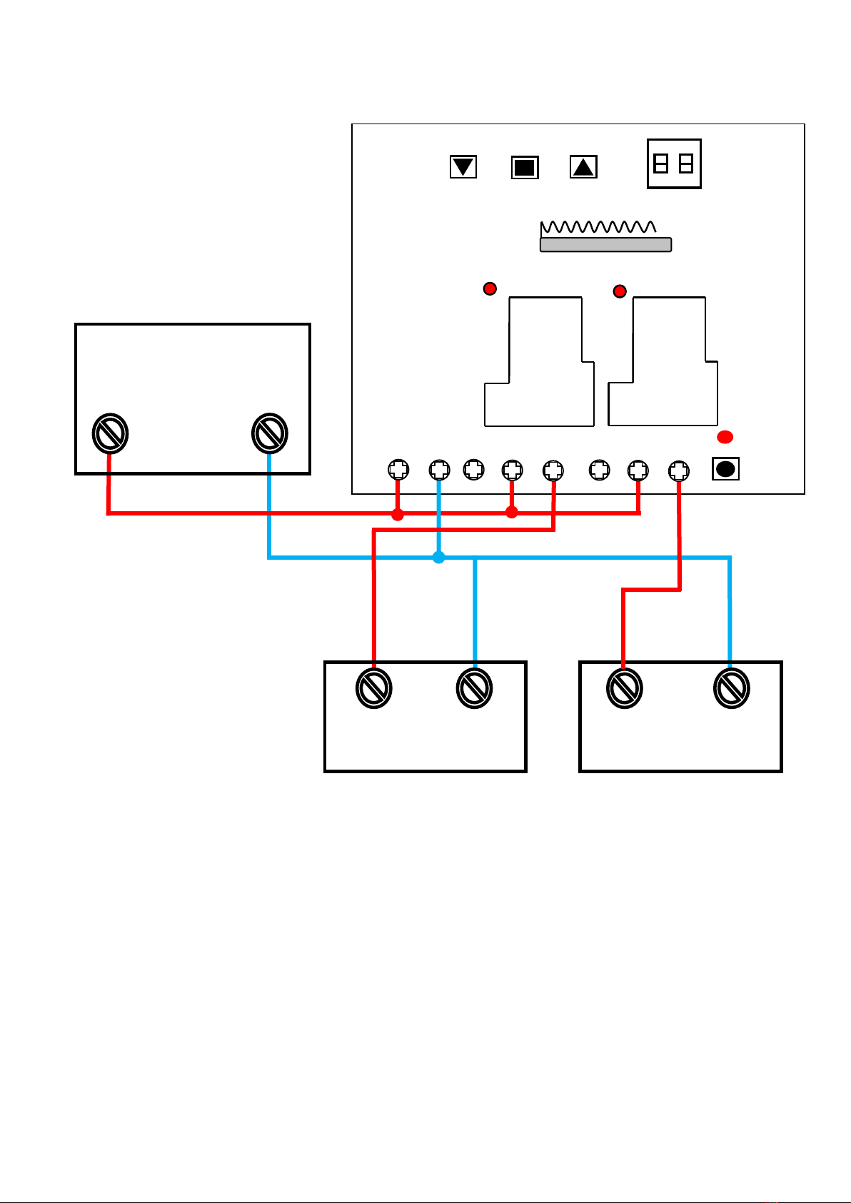
1) If you want to control the AC 220V equipment, you can connect the receiver, the equipment and the AC power according following circuit diagram 1,
then you use the transmitter to control the equipment.
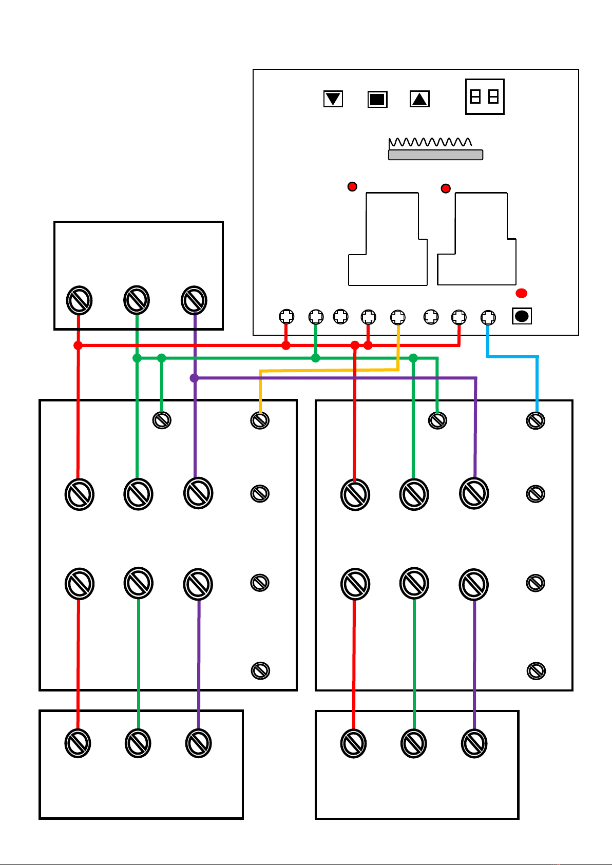
2) If you want to control the AC 380V equipment, you can connect the receiver, the 380V contactor, the 380V equipment and the 380V power
according following circuit diagram 2, then you use the transmitter to control the AC 380V equipment.
Setting different control modes:
We have set the receiver as Self-locking control mode before delivery. If you want to use other control modes, do as following operation:
1) Setting Self-locking mode: Turn on the dip switch 2, and turn off the dip switch 1.
Mode Self-locking (working with transmitter CG-2): Press -> On; Press again -> Off.
Press button 1 of the transmitter: The relay 1 is activated, and the contactor 1 is connected, the equipment 1 works.
Press button 1 again: The relay 1 is deactivated, and the contactor 1 is disconnected, the equipment 1 stops working.
Press button 2 of the transmitter: The relay 2 is activated, and the contactor 2 is connected, the equipment 2 works.
Press button 2 again: The relay 2 is deactivated, and the contactor 2 is disconnected, the equipment 2 stops working.
2) Setting Momentary mode: Turn off the dip switch 1 and 2.
Mode Momentary (working with transmitter CG-2): Press and hold -> On; Release -> Off.
Press and hold button 1 of the transmitter: The relay 1 is deactivated, and the contactor 1 is connected, the equipment 1 works.

SHENZHEN FLYING INDUSTRY DEVELOPMENT CO.,LTD
http://www.carymart.com E-Mail: sale@carymart.com
Release button 1: The relay 1 is deactivated, and the contactor 1 is disconnected, the equipment 1 stops working.
Press and hold button 2 of the transmitter: The relay 2 is activated, and the contactor 2 is connected, the equipment 2 works.
Release button 2: The relay 2 is deactivated, and the contactor 2 is disconnected, the equipment 2 stops working.
3) Setting Interlocking mode: Turn on the dip switch 1, and turn off the dip switch 2.
Mode Interlocking (working with transmitter CG-3 or CB-3-2): Press -> On; Press another button -> Off.
Press button ▼ of the transmitter: The relay 1 is deactivated, and the contactor 1 is connected, the equipment 1 works.
Press button ■ of the transmitter: The relay 1 is deactivated, and the contactor 1 is disconnected, the equipment 1 stops working.
Press button ▲ of the transmitter: The relay 2 is activated, and the contactor 2 is connected, the equipment 2 works.
Press button ■ of the transmitter: The relay 2 is deactivated, and the contactor 2 is disconnected, the equipment 2 stops working.
4) Setting Mixed mode (Momentary + Self-locking): Turn on the dip switch 1 and 2.
Mode Momentary for channel 1 (working with transmitter CG-2): Press and hold -> On; Release -> Off.
Press and hold button 1 of the transmitter: The relay 1 is deactivated, and the contactor 1 is connected, the equipment 1 works.
Release button 1: The relay 1 is deactivated, and the contactor 1 is disconnected, the equipment 1 stops working.
Mode Self-locking for channel 2 (working with transmitter CG-2): Press -> On; Press again -> Off.
Press button 2 of the transmitter: The relay 2 is activated, and the contactor 2 is connected, the equipment 2 works.
Press button 2 again: The relay 2 is deactivated, and the contactor 2 is disconnected, the equipment 2 stops working.
Manual buttons:
Press manual button ▼ of the receiver: The relay 1 is deactivated, and the contactor 1 is connected, the equipment 1 works.
Press manual button ■ of the receiver: The relay 1 is deactivated, and the contactor 1 is disconnected, the equipment 1 stops working.
Press manual button ▲ of the receiver: The relay 2 is activated, and the contactor 2 is connected, the equipment 2 works.
Press manual button ■ of the receiver: The relay 2 is deactivated, and the contactor 2 is disconnected, the equipment 2 stops working.
How to pair the transmitter to the receiver:
1) Press the learning button of the receiver, signal LED on the receiver is on, the receiver enters into status of LEARNING.
2) Press any button on transmitter within 5 seconds, if signal LED flashes 2 times then turns off, it means learning is successful.
3) The receiver can learn several transmitters with different codes.
Delete all transmitters:
We have learned the transmitter to the receiver. If you don’t want the receiver to work with the transmitter, you can delete all codes of the transmitters
which are stored in the receiver.
Operation: Pressing the learning buttons of the receiver for 6~7 seconds until the signal LED on the receiver flashes 3 times, then release the
learning button. That means all stored codes have been deleted successfully.
SHENZHEN FLYING INDUSTRY DEVELOPMENT CO.,LTD
http://www.carymart.com E-Mail: sale@carymart.com
L N
AC 220V POWER
AC 220V Equipment 2
L N L N
AC 220V Equipment 1
S2PU-AC380
Circuit Diagram 1
NC1
Relay1
Relay2
Status LED 1
Status LED 2
Signal LED
Learning
button
Antenna
RF module
NC2
NO1
COM1
NO2
COM2
L N
1
2
ON
dip switch
Manual buttons
SHENZHEN FLYING INDUSTRY DEVELOPMENT CO.,LTD
http://www.carymart.com E-Mail: sale@carymart.com
L1 L2 L3
AC 380V Equipment 1
L1 L2 L3
AC 380V Equipment 2
L1
1
T3
T2
T1
L3
L2 5 3
6
4
2
A2
14
NO
A2
13
NO
A1
AC 380V Contactor 1
L1
1
T3
T2
T1
L3
L2 5 3
6
4
2
A2
14
NO
A2
13
NO
A1
AC 380V Contactor 2
L1 L2 L3
AC 380V POWER
S2PU-AC380
Circuit Diagram 2
NC1
Relay1
Relay2
Status LED 1
Status LED 2
Signal LED
Learning
button
Antenna
RF module
1
2
ON
dip switch
NC2
NO1
COM1
NO2
COM2
L1 L2
Manual buttons
This manual suits for next models
1
Table of contents
Other SHENZHEN FLYING INDUSTRY DEVELOPMENT Receiver manuals


