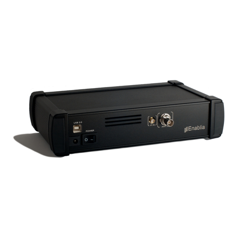
Enablia TitanSDR User manual

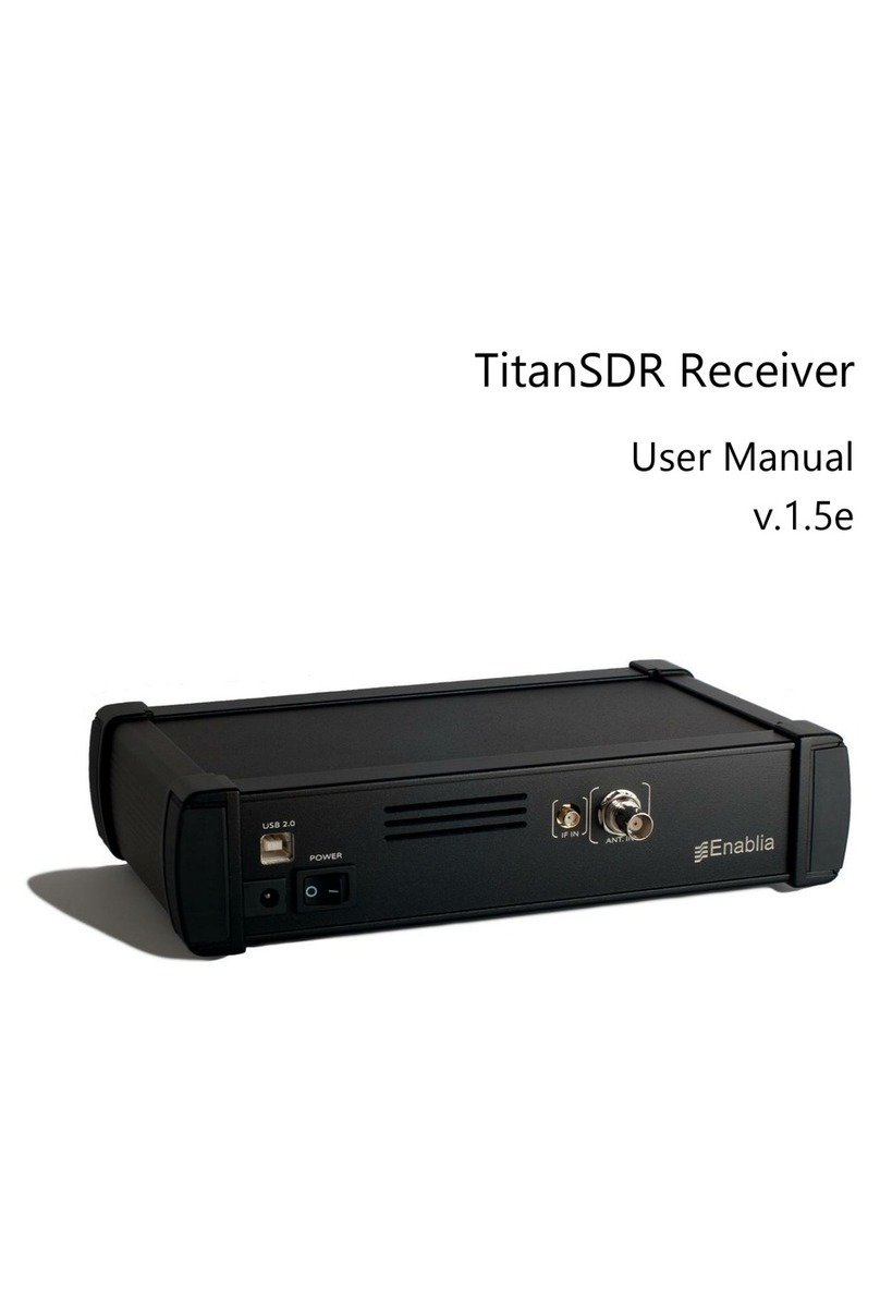
TitanSDR Receiver
User Manual
v.1.2e

Enablia S.r.l. (Italy) 2012
Before using the receiver, read carefully the Installation Manual and the User
Manual.
The symbol of the crossed out wheelie bin indicates
that in the European Union this product, and all
items marked with this symbol, cannot be disposed
of as unsorted waste but must be disposed of
separately at the end of their useful life

TitanSDR –User Manual 3
Index
1. Introduction.................................................................................. 5
1.1 User interface architecture....................................................................... 6
1.2 Panoramic Scope, Wideband Scope and Narrowband Scope ....... 8
1.3 Software startup.......................................................................................... 9
2. Receiver Mode .......................................................................... 11
2.1 Panoramic Scope .................................................................................... 12
2.1.1 Front End settings ...................................................................................... 12
2.1.2 Spectrum settings...................................................................................... 13
2.1.3 Management of wideband channels .................................................. 17
2.2 Wideband Scope ..................................................................................... 20
2.2.1 Spectrum settings...................................................................................... 20
2.2.2 Management of narrowband channels............................................... 23
2.2.3 Recording of wideband channels......................................................... 27
2.3 Narrowband Scope ................................................................................. 29
2.3.1 Spectrum settings...................................................................................... 30
2.3.2 Tuning of narrowband channel.............................................................. 34
2.3.3 Demodulation settings ............................................................................. 36
2.3.4 Listening demodulated audio ................................................................ 39
2.3.5 Gain control............................................................................................... 41
2.3.6 Audio streaming through Virtual Audio Cables (VAC) ....................... 42
2.3.7 Audio streaming by LAN .......................................................................... 43
2.3.8 Recording of narrowband channels ..................................................... 47
3. Player mode............................................................................... 49
4. Advanced Operations .............................................................. 52
4.1 Session saving and loading .................................................................... 52
4.1.1 Session saving ............................................................................................ 52
4.1.2 Session loading.......................................................................................... 54
4.2 NB Channels List........................................................................................ 55

TitanSDR –User Manual 4
4.3 Memory of narrowband channels......................................................... 57
4.3.1 Memorization............................................................................................. 58
4.3.2 Allocation of memorized channels........................................................ 61
4.3.3 Memory settings modifications ............................................................... 62
4.3.4 Removal of memorized channels.......................................................... 63
4.4 Scheduling of recordings ........................................................................ 64
4.4.1 Scheduling of a new wideband\narrowband channel.................... 64
4.4.2 Task Editor window ................................................................................... 67
4.4.3 Managing scheduled channels............................................................ 71
4.4.4 Allocation of scheduled channels......................................................... 73
4.5 Options ....................................................................................................... 78
4.5.1 Independent View.................................................................................... 78
4.5.2 Panoramic ................................................................................................. 79
4.5.3 Wideband .................................................................................................. 79
4.5.4 Narrowband .............................................................................................. 81
4.5.5 Output Files Name .................................................................................... 83
4.5.6 Storage ....................................................................................................... 85
4.5.7 Session......................................................................................................... 86
5. Appendix.................................................................................... 88

TitanSDR –User Manual 5
1. Introduction
This manual describes the TitanSDR user interface and its mode of use.
Before using the product, make sure to have correctly performed all the steps in
the Installation Manual.
TitanSDR is an HF multi-channel receiver allowing up to four independent
wideband channels within the 0-40MHz band and several narrowband channels
(up to 8, 16 and 40 in the TitanSDR_8, TitanSDR_16 and TitanSDR_40 versions of the
product, respectively), which can be tuned within wideband channels.
Each narrowband channel supports, at the same time, demodulation, recording
(onto WAV files) and streaming of demodulated signals to: VACs (Virtual Audio
Cables), sound cards and Hoka Electronic CODE300 decoders (via LAN).
Figure 1 exemplifies diagrammatically the operation described above.
Figure 1 - Functional diagram

TitanSDR –User Manual 6
1.1 User interface architecture
Figure 2 shows schematically the user interface architecture.
Figure 2 - User interface architecture
The user interface is composed of:
Main Toolbar
Panoramic Scope
Wideband Scope
Narrowband Scope
On the Main Toolbar (Figure 3) there are a series of drop-down menus (File, Mode,
NB List, Memory, Schedule, View, Options) that allow to access the features
described in detail in Chapters 2, 3, 4 of this manual.
Figure 3 - Main Toolbar

TitanSDR –User Manual 7
Panoramic Scope, Wideband Scope and Narrowband Scope are windows in
which visualization and control of panoramic spectrum, wideband channels and
narrowband channels, can be performed, respectively.
As illustrated in Figure 2, Wideband Scope and Narrowband Scope are positioned
under the Panoramic Scope, which in turn is just under the Main Toolbar.
In order to make resize of windows possible, these are separated by splitters,
namely graphics draggable separators, which allow to increase (or decrease) the
size of the window of interest, to the detriment (or advantage) of the others.
Clicking on a splitter, its position can be moved by mouse dragging (with the left
mouse button hold down).
Figure 4 - Splitters drag directions
Figure 4 shows directions in which splitters can be dragged inside the user
interface.
Note the presence of splitters also within windows of Wideband and Narrowband
Scope (see Chapter 1.2 for a detailed description). Figure 5 shows a screenshot of
the user interface during typical operation.

TitanSDR –User Manual 8
Figure 5 - TitanSDR user interface
1.2 Panoramic Scope, Wideband Scope and Narrowband Scope
In this paragraph, the high-level structure of Panoramic Scope, Wideband Scope
and Narrowband Scope is described.
Panoramic Scope:
It is composed of its own toolbar, a panoramic spectrum window and a reference
bar representing the frequency axis. The toolbar contains commands that allow to:
• control front-end settings
• manage spectrum settings
• allocate and deallocate wideband channels
The panoramic spectrum window shows spectrum of the 0 - 32MHz band
managed by the receiver (see par. 4.5.2 to show up to 40MHz). The reference bar
is draggable horizontally, after at least one frequency zoom-in step (see Chapter
2.1.2).

TitanSDR –User Manual 9
Wideband Scope:
The Wideband Scope shows the spectrum of the wideband channel which is
currently selected on the Panoramic Scope, at a higher resolution and its
“waterfall" representation. The frequency bar (placed below the spectrum plot) is
draggable horizontally after at least one frequency zoom-in step (see Chapter
2.2.1).
Spectrum plot and waterfall display are separated by a splitter, which allows to
vary the vertical dimension of the two windows (Figure 4).
Narrowband Scope:
The Narrowband Scope shows the spectrum of the narrowband channel which is
currently selected within the Wideband Scope, with a higher resolution and its
“waterfall” representation.
Spectrum plot and waterfall display are separated by a splitter, which allows to
vary the vertical dimension of the two windows (Figure 4).
Panoramic Scope, Wideband Scope and Narrowband Scope can be possibly
shown or hidden by selecting or deselecting the corresponding items of the "View"
drop-down menu on the main toolbar (Figure 6).
Figure 6 - View menu
1.3 Software startup
The user interface, shown in Figure 8, appears by double-clicking on the TitanSDR
software icon (see Figure 7).
Figure 7 - TitanSDR software icon

TitanSDR –User Manual 10
Figure 8 - User interface of TitanSDR
TitanSDR can be operated in the following two modes:
Receiver Mode
Player Mode
with the ability to switch between them without restarting the software.
Receiver Mode: software allows to control the receiver and to manage all
operations on radio channels (all of the functions of this mode are described in
Chapter 2).
Player Mode: software allows to playback files (written in a proprietary format)
which resulted from previous recording of wideband channels in Receiver Mode
(see Section 2.2.3) and to perform the same operations allowed on wideband
channels in Receiver Mode (allocation and recording of narrowband channels,
demodulation, listening of demodulated audio, data streaming by VAC, LAN, ...).
All Player Mode functions are described in Chapter 3.
Mode choice is made through the menu "Mode" (Figure 9) on the Main Toolbar.
The default setting is Receiver Mode.
Figure 9 - Mode setting

TitanSDR –User Manual 11
2. Receiver Mode
After selecting the Receiver Mode (from menu "Mode" on the Main Toolbar), as
shown in Figure 9, press the connect USB button illustrated in Figure 10.
Figure 10 - USB button before connection
This button is used to start communication between the software and the receiver.
If connection is successful, the button symbol changes color (from red to green,
see Figure 11) and the input 0-32MHz spectrum appears on the Panoramic Scope
(Figure 12).
Figure 11 - USB button after connection
Figure 12 - User interface after successful connection with receiver

TitanSDR –User Manual 12
2.1 Panoramic Scope
2.1.1 Front End settings
Receiver Front-end settings can be changed by the Front End controls group of the
Panoramic Scope toolbar (Figure 13).
Figure 13 - FrontEnd controls group
Settings may regard:
• Selection of a preselection filter
• Change of input attenuation value
• Receiver input selection
Selection of preselection filters:
The list of possible sixteen preselectors appears by clicking on the first drop-down
menu of the FrontEnd controls group (Figure 14). Each preselector/filter is
characterized by its own passband, whose frequency extremes are indicated in
the list. The All Pass choice is also possible (default), causing the receiver to
perform no preselection on RF input signal.
Figure 14 - Preselection filters list

TitanSDR –User Manual 13
Setting of the RF attenuation value:
RF attenuation can be set from 0dB to 30dB, in steps of 10 dB. Clicking on the
second drop-down menu of the FrontEnd controls group, a list appears of
attenuation values that can be selected (Figure 15). Default value is 0dB.
Figure 15 - List of selectable attenuation values
Receiver input selection:
By clicking on the third drop-down menu of the FrontEnd controls group, selection
can be made of the receiver input (Figure 16). The “IF” choice corresponds to the
SMA connector marked "IF IN" on the receiver rear panel, whilst the “HF” choice
corresponds to the BNC connector marked "ANT. IN ". Default receiver input is
“HF”.
Figure 16 - Receiver input selection
2.1.2 Spectrum settings
The graphical settings of the Panoramic Scope spectrum can be changed by the
Spectrum controls group of the Panoramic Scope toolbar (Figure 17).
Figure 17 - Spectrum controls group
The actions that can be performed are:
• selection of windowing (for FFT)
• selection of spectrum averaging time period
• spectrum zoom/dezoom
Furthermore, in order to shift the displayed frequency interval, dragging of the
frequency axis bar is also possible.

TitanSDR –User Manual 14
Selection of windowing (for FFT):
By clicking on the first drop-down menu of the Spectrum controls group, a list
appears of the four possible windows that can be selected (Figure 18). Default
window is “Blackman”.
Figure 18 - Windowing alternatives
Selection of spectrum averaging time period:
By clicking on the second drop-down menu of the Spectrum controls group, a list
appears of possible averaging time periods that can be selected (Figure 19).
Default setting is "NO AVG", meaning that spectra are plotted on the Panoramic
Scope without any averaging.
Figure 19 - Spectrum averaging time periods
Spectrum zoom\dezoom
Spectrum can be zoomed/dezoomed with respect to :
•frequency (Horizontal zoom)
• amplitude (Vertical zoom)
Horizontal (frequency) zoom/dezoom
Horizontal zoom/dezoom allows to halve/double the frequency spectrum span,
aiming at a specific center frequency value, corresponding to a vertical white line
which can be placed by left clicking on the wanted position (Figure 20). After

TitanSDR –User Manual 15
mouse click a hint label appears near the vertical line indicating the
corresponding frequency.
Figure 20 - Panoramic Scope spectrum
Buttons for horizontal zoom/dezoom are shown in Figure 21 and are positioned
within the Spectrum controls group of the Panoramic Scope toolbar.
Figure 21 - Horizontal zoom/dezoom buttons
Figure 22 shows the Panoramic Scope after zooming the spectrum of Figure 20, by
clicking on the horizontal zoom button (the one marked with a “+”).
Figure 22 - Panoramic Scope after horizontal zoom
Vertical (amplitude) zoom/dezoom:
In order to perform also amplitude zoom/dezoom, it is necessary to make
corresponding buttons visible in the Spectrum controls group. To this aim, click on
the menu item "Centered zoom", after selecting “Panoramic” in the Main Toolbar
“Options” menu (Figure 23).

TitanSDR –User Manual 16
Figure 23 - Centered Zoom option
This operation will cause a white horizontal line to appear also on the Panoramic
Scope spectrum (Figure 24) and the vertical zoom/dezoom buttons to appear
within the Spectrum controls group (Figure 25). Vertical zoom/dezoom allows to
halve/double the amplitude spectrum range, aiming at a specific center
amplitude value, corresponding to the horizontal white line, which can be set by
left clicking or selecting and dragging it on the wanted position.
Figure 24 - Centered zoom horizontal and vertical target lines
Figure 26 shows the Panoramic Scope after zooming the spectrum of Figure 24, by
clicking on the vertical zoom button (the one marked with a “+” and a “V”).
Figure 25 - Vertical zoom/dezoom buttons
Figure 26 - Panoramic Scope after vertical zoom

TitanSDR –User Manual 17
The position of the horizontal and vertical white lines can be changed by left
clicking or selecting and dragging them to the desired position. After clicking, hint
labels appears near the vertical and horizontal lines indicating the corresponding
frequency and amplitude, respectively.
Dragging of the frequency axis bar
After having zoomed once (at least), the displayed frequency interval can be
shifted downwards or upwards by simply left clicking on the frequency axis bar of
the Panoramic Scope (Figure 27) and dragging it leftward or rightward,
respectively.
Figure 27 - Frequency axis bar of the Panoramic Scope
2.1.3 Management of wideband channels
The WB Channels controls group of the Panoramic Scope toolbar (Figure 28) allows
to perform the following operations:
allocation of a wideband channel
selection of a previously allocated wideband channel
tuning of a wideband channel (by mouse dragging and dropping its
shaded area)
deallocation (removal) of a wideband channel
Figure 28 - WB Channels controls group
Allocation of a wideband channel:
By clicking on the "ADD" button of the WB Channels controls group, a list appears
of available bandwidth sizes (Figure 29) for the new wideband channel to allocate
(see Appendix).

TitanSDR –User Manual 18
Figure 29 - List of available bandwidth sizes
A new wideband channel is allocated by clicking on one of the available
bandwidth sizes. Its position and frequency extent is represented by a colored
shaded area on the Panoramic Scope spectrum (Figure 30), whilst its center
frequency is indicated in the edit box of the WB Channels controls group (Figure
28).
Figure 30 - Wideband channel shaded area
By default the new wideband channel is allocated within the Panoramic Scope at
the far left of the displayed spectrum. The allocated channel is assigned one of
the following names: WB1, WB2, WB3, WB4.
To facilitate identification of wideband channels and to distinguish them from one
another, their shaded areas are assigned a color, based on the following color
convention:
- WB1: RED shaded area
- WB2: GREEN shaded area

TitanSDR –User Manual 19
- WB3: BLUE shaded area
- WB4: PURPLE shaded area
Selection of a wideband channel
When more than one wideband channel has been allocated (Figure 31), a
specific wideband channel can be selected by clicking on its name in the first
drop-down menu of the WB Channels controls group (Figure 32).
Figure 31 - Sample scenario with four wideband channels
Figure 32 - WB Channels drop-down menu
For each allocated wideband channel, both center frequency and bandwidth
are provided in the same drop-down menu. By selecting a wideband channel, its
shaded area becomes brightly colored.
Tuning of wideband channels
Tuning of the selected wideband channel within the Panoramic Scope spectrum
can be obtained by dragging its shaded area, after having clicked on it. While
dragging, the wideband channel center frequency is modified accordingly in the
frequency edit box of the WB Channels controls group (Figure 33).

TitanSDR –User Manual 20
Figure 33 - Center frequency edit box
The unit of measurement of the wideband channel center frequency can be
selected by the second drop-down menu of the WB Channels controls group
(Figure 34). Possible choices are: Hz, KHz or MHz .
Figure 34 - Unit of measurement of WB channel center frequency
Deallocation of wideband channels
The selected wideband channel can be deallocated by clicking on the trash
button (Figure 35) of the WB Channels controls group (Figure 33).
Figure 35 - Trash button
As a result of this action, its shaded area disappears from the Panoramic Scope
spectrum and its name is removed from the wideband channels drop-down menu
(of Figure 32).
In order to perform deallocation of a wideband channel, it must be “empty”, i.e.
no narrowband channel must be present (allocated) inside it (see par. 2.2.2).
2.2 Wideband Scope
2.2.1 Spectrum settings
The graphical settings of the Wideband Scope spectrum can be changed by the
Spectrum controls group of the Wideband Scope toolbar (Figure 36).
Figure 36 - Spectrum controls group
Other manuals for TitanSDR
5
Table of contents
Other Enablia Receiver manuals
