Sherbourn SR-8100 User manual


Important Safety Precautions and Explanation of Symbols
The exclamation point within an equilateral triangle is intended to alert the user to the presence of
important installation, operation, and service instructions in this manual.
The lightning ash with arrowhead symbol within an equilateral triangle is intended to alert the user
to the presence of uninsulated dangerous voltages within the enclosure that may be of sufcient
magnitude to constitute a risk of electrical shock to the user.
Please read this manual thoroughly before attempting to install, congure, or operate the Sherbourn
SR-8100. After successful installation and conguration of the SR-8100, be sure to retain this manual
in a safe place for future reference.
Safety is a key component to a long lasting and trouble free installation. Please read and follow
all instructions and heed all warnings on the SR-8100 and in this manual. The vast majority of the
subsequent safety precautions are common sense. If you are not comfortable with the installation
of audio/video entertainment equipment, you should seek the services of a qualied installation
professional or call us for help.
WARNING: TO REDUCE THE RISK OF FIRE OR ELECTRIC SHOCK, DO NOT USE THE
SR-8100 NEAR WATER OR IN WET LOCATIONS, DO NOT EXPOSE IT TO RAIN OR MOISTURE,
DO NOT EXPOSE IT TO DRIPPING OR SPLASHING FROM OTHER SOURCES, AND ENSURE
THAT NO OBJECTS FILLED WITH LIQUIDS (SUCH AS VASES) ARE PLACED ON IT. DOING SO
MAY RESULT IN DAMAGE TO THE SR-8100 AND THE RISK OF ELECTRIC SHOCK, WHICH MAY
RESULT IN BODILY INJURY OR DEATH.
WARNING: TO REDUCE THE RISK OF ELECTRIC SHOCK, DO NOT REMOVE THE COVER
FROM THE SR-8100. THERE ARE NO USER-SERVICEABLE PARTS INSIDE THE SR-8100.
REFER ALL SERVICE TO QUALIFIED SERVICE PERSONNEL.
Do not install the SR-8100 near or above any heat sources such as radiators, heating vents, or other
apparatus’ that produce heat. Do not block any ventilation openings or heat sinks. Avoid installing
the SR-8100 directly above other heat-producing equipment unless sufcient ventilation or forced-air
cooling is provided.
Do not install the SR-8100 in locations without proper ventilation. The SR-8100 should not be operated
on a bed, sofa, rug, or similar surface that may block vents. The SR-8100 should not be installed in an
enclosed location such as a bookcase, cabinet, or closed equipment rack unless sufcient forced-air
ventilation is provided.
Always install your SR-8100 according to the manufacturer’s instructions and only use attachments or
accessories specied by the manufacturer.
Do not install the SR-8100 on any stand, shelf, or other piece of furniture that is unable to support its
weight. If a cart is used to move the SR-8100, use caution to avoid injury from tip-over.
Connect the SR-8100 only to power sources of the correct voltage (as shown in this manual and on
the SR-8100).
Protect power supply cables from being pinched, walked on, or otherwise damaged. Be especially
careful where the power cable enters the power outlet and the SR-8100 unit.
Only connect the SR-8100 to an electrical outlet or extension cord of appropriate type and rating.
DO NOT defeat the safety purpose of a grounding or polarized plug by removing ground pins or using
unsafe adapters. A polarized plug has two blades - one wider than the other. A grounding plug has a
third ground prong in addition to the two main conductors. The wide blade or third grounding prong is
provided for your safety. If the provided plug does not t your outlet, consult an electrician to replace
your obsolete outlet. If you replace the power cord on the SR-8100, only use one of similar type and
equal or greater current rating.
The power cable for the SR-8100 should be unplugged from the outlet during severe electrical storms,
or when unused for a long period of time.
!
!

Only replace the fuse(s) in the SR-8100 with a fuse(s) of proper value and voltage rating.
The SR-8100 should only be cleaned as directed in the manual. Avoid spraying liquids directly onto the
SR-8100 and NEVER spray liquids into the vents. Care should be taken so that small objects do not
fall into the inside of the SR-8100.
You should seek service for your SR-8100 by qualied service personnel if any of the following occur:
1. The power-supply cord or the plug has been damaged.
2. Objects or liquid have fallen or spilled into the vents.
3. The SR-8100 has been exposed to rain.
4. The SR-8100 exhibits a marked change in performance.
5. The SR-8100 has been dropped, or its enclosure or chassis is damaged.
NOTE: TO COMPLETELY DISCONNECT THE SR-8100 FROM THE AC POWER MAINS,
DISCONNECT THE AC POWER CORD FROM THE AC RECEPTACLE.
NOTE: THE SR-8100 AC POWER CORD MUST REMAIN READILY ACCESSIBLE AT ALL TIMES.
!
CAUTION
CAUTION: TO REDUCE THE RISK
OF ELECTRICAL SHOCK, DO
NOT REMOVE COVER. NO USER
SERVICEABLE PARTS INSIDE.
REFER SERVICING TO QUALIFIED
SERVICE PERSONNEL.
Antenna lead-in wire
Grounding conductors
(NEC section 810-20)
Antenna discharge unit
(NEC section 810-20)
Power service grounding
electrode system
(NEC art 250, part H)
Ground clamps
Ground clamp
Electric service
equipment
NEC - National Electrical Code

FCC Interference Statement
Note: This equipment has been tested and found to comply with the limits for a Class B digital
device, pursuant to Part 15 of the FCC rules. These limits are designed to provide reasonable
protection against harmful interference in a residential installation. This equipment generates,
uses and can radiate radio frequency energy and, if not installed and used in accordance with
the instructions, may cause harmful interference to radio communications. However, there is no
guarantee that the interference will not occur in a particular installation. If this equipment does
cause harmful interference to radio or television reception, which can be determined by turning the
equipment off and on, the user is encouraged to try to correct the interference by one or more of the
following measures:
Reorient or relocate the receiving antenna.
Increase the separation between the equipment and receiver.
Connect the equipment to an outlet on a circuit different from that of the receiver.
Consult the manufacturer or an experienced radio/TV technician for help.
For questions regarding service, please contact:
Sherbourn Technologies, Inc.
131 SE Parkway Court
Franklin, Tennessee
37064
Tel 1-877-366-8324
www.sherbourn.com

Page 1
SR-8100: User Manual
Contents
Important Safety Precautions and Explanation of Symbols
The Sherbourn SR-8100 ............................................................................2
About This Manual......................................................................................2
Mechanical and Environmental ..................................................................3
Features .....................................................................................................4
Controls and Connectors............................................................................5
Conguration and Operation ....................................................................18
Example Input Conguration ....................................................................46
Connectivity..............................................................................................47
Care and Maintenance .............................................................................48
Installing the Rack Mount Kit....................................................................49
Troubleshooting........................................................................................50
Sherbourn Technologies, LLC Limited Warranty ......................................51
Notes ........................................................................................................53
SR-8100
7.1 Channel AV Receiver

Page 2
SR-8100: User Manual
The Sherbourn SR-8100
Thank you for choosing the Sherbourn SR-8100 7.1 Channel Home Theater Receiver. The
SR-8100 combines incredibly fast, clean video switching, all the latest surround sound decoding
modes, true audiophile sound quality, an intuitive, easy to use menu structure, and seven channels
of superb quality amplication to give you the ultimate performance attainable today in a home
theater receiver.
The SR-8100 forms the perfect basis for an exceptional sounding home theater system. We’re
very proud of our achievement, and we trust you’ll enjoy listining to it as much as we’ve enjoyed
developing it.
Enjoy,
The Sherbourn Team
About This Manual
This manual will provide you with all the information you need to install and congure the SR-8100
to achieve its optimum potential. The manual also includes a brief summary of the features offered
by the SR-8100 and descriptions of how the controls work.
You may wish to record serial numbers or other purchase information on the Notes page at the back
of this manual.

Page 3
SR-8100: User Manual
Mechanical and Environmental
Dimensions:
17” wide x 4” high x 16.5” deep (includes feet, connectors, no rack kit);
22” wide x 8.5” high x 21” deep (boxed)
Weight: 25 lbs / 12 kg (unboxed); 34 lbs / 16 kg (boxed)
Rack mountable: Yes (rack mount kit included)
Power requirements:
115 VAC or 230 VAC +/- 10% @ 50 / 60 Hz (auto selected)
Ventilation and cooling:
To avoid overheating, be sure to provide adequate clearance and ventilation. You should provide a
minimum of 4 inches clearance on all sides of the SR-8100 (including the back). If the SR-8100 is to
be installed in an enclosed space, be sure to provide adequate ventilation or forced air cooling.

Page 4
SR-8100: User Manual
Features
The Sherbourn SR-8100 is a reference-caliber home theater receiver with high-performance
audio and video processing and seven channels of audiophile quality Class A/B amplication. The
SR-8100 provides plenty of audio and video inputs for most video enthusiasts, supports all the
latest surround sound decoding options, and delivers enough power to drive most speakers to
satisfying levels in a typical small-to-medium home theater. The SR-8100 includes the Sherbourn
Advanced Room Correction System™, which automatically calibrates your speakers and the rest
of your system to deliver clean and amazingly accurate sound with just a few simple commands.
If you prefer to congure your system manually, the SR-8100 also includes three separate banks
of powerful manual parametric equalization controls. Our sophisticated yet comprehensive menu
system even lets you compare your automatic and manual EQ curves to a at target curve, and
choose the one you prefer with the touch of a button.
Some of the more important features of the SR-8100 include:
• 4 HDMI 1.4 inputs and one HDMI 1.4 output.
• Full support for 3D, CEC, and ARC.
• Xpressview™ HDMI switching for fast, clean input selection.
• High Denition Surround Sound with Twin Cirrus® 32-bit dual-core xed-point DSP’s.
• Supports Dolby Digital, Dolby Digital EX, Dolby Digital Plus, Dolby TrueHD, Dolby Pro Logic IIx,
Dolby Pro Logic IIz, DTS, DTS ES, DTS HD, DTS HD Master Audio, DTS Neo:6, S/PDIF, PCM
8 channel (note: some audio formats are only supported via HDMI).
• Sherbourn Advanced Room Correction System™
(calibrated measurement microphone included).
• Flexible bass management, with selectable 12dB or 24 dB per octave crossover lters,
congurable in precise 5 Hz steps below 80 Hz (and 10 Hz steps above 80 Hz).
• Powerful parametric equalization provides exceptionally exible manual control
(3 separate manual EQ banks; each has 11 bands per each main channel and 3 bands for sub).
• Separate 7.1 channel pure analog direct input for connecting SACD or other surround sources.
• Surround rear amplier channels may be re-tasked to bi-amplify front channel speakers.
• Integrated Bluetooth 3.0 for CD quality audio from mobile devices with apt-X™.
• Zone 2 and Zone 3 audio support.
• A balanced subwoofer output (an XLR-to-RCA balanced-to-unbalanced adapter is included).
• Video-On-Standby sends audio and video to the display even when the SR-8100
is in standby mode.
• Last Video Memory allows viewing of one source while listening to another.
• High quality headphone amp included for private listening.
• Comprehensive control via full-color OSD (on screen display) over live video with adjustable
transparency.
• All adjustments are made in real time over live video and audio.
• Ergonomic custom remote control included.
• Sherbourn ve year warranty.
You can nd more information about the SR-8100 Home Theater Receiver on our website at
www.sherbourn.com.

Page 5
SR-8100: User Manual
Controls and Connectors
Front Panel - Controls and Indicators
1 9872 3 654
1. Input Selector (rotary encoder)
Turn this to quickly select between congured inputs; once the correct input is selected, press it to
“lock in” your choice.
Note: The Input Selector can only select between inputs that are enabled. To access inputs
which are not enabled, you must use the Input Menu.
2. Standby Button
Press this to switch the SR-8100 from Standby to On; press it again to return the SR-8100 to
Standby mode. (The rear panel AC power switch must be On.)
3. Standby LED
This LED is red when the SR-8100 is in Standby mode, and blue when the SR-8100 is On.
4. Front Panel Display
Large, clear, easy to read VFD status display.
5. Menu Button
Press this button to activate the conguration menu.
6. Left, Right, Enter, Up, Down, and Return Buttons
When the conguration menu is active, these buttons are used to navigate the menu.
When the menu is not active, use the Left and Right buttons to select between inputs.
7. Calibration Microphone Jack
Connect the (included) calibration microphone to this jack when you wish to perform automatic room
calibration using the Sherbourn Advanced Room Correction System. For the most accurate results,
use only the included calibration microphone.

Page 6
SR-8100: User Manual
8. Headphone Jack
Connect any standard pair of stereo headphones for high-quality personal listening. When you plug
in a pair of headphones, the main volume is automatically muted.
9. Volume Control
The Volume Control on the SR-8100 is a rotary encoder that instructs the digitally controlled analog
resistor ladder network volume control. (The dot on the knob does not indicate the volume setting.)

Page 7
SR-8100: User Manual
Rear Panel
HDMI 1 HDMI 2 HDMI 3 HDMI 4 HDMI OUT/ARC
AN 1 AN 2 AN 3 AN 4 FL SL CNT SBL
FR SR SUB SBR
SUB OUT STEREO IN 7.1 ANALOG IN DIGITAL IN
CO 1 CO 2
OPT1 OPT2
L R L R L R
L
R
SBL/SBR
ZONE 2
BACK CHNL MIX ZONE 2 ZONE 3 IR TRIGGER OUT USB
IN OUT 1 2
FM
AM
220V 115V
RS232 CONTROL
SBL SL FL CNT FR SR SBR
7.1 OUT
ANTENNAS

Page 8
SR-8100: User Manual
Rear Panel - Control and Antenna Connections
21
IR TRIGGER OUT
IN OUT 1 2
43 5
HDMI 1 HDMI 2 HDMI 3 HDMI 4 HDMI OUT/ARC
AN 1 AN 2 AN 3 AN 4 FL SL CNT SBL
FR SR SUB SBR
SUB OUT STEREO IN 7.1 ANALOG IN DIGITAL IN
CO 1 CO 2
OPT1 OPT2
L R L R L R
L
R
SBL/SBR
ZONE 2
BACK CHNL MIX ZONE 2 ZONE 3 IR TRIGGER OUT USB
IN OUT 1 2
FM
AM
220V 115V
RS232 CONTROL
SBL SL FL CNT FR SR SBR
7.1 OUT
ANTENNAS
FM
AM
ANTENNAS
RS232 CONTROL
1. AM Antenna
Connect a standard AM antenna (included) to these terminals.
2. FM Antenna
Connect a standard FM antenna (included) to these terminals.
3. IR Remote Input and Output
Connect a remote IR detector (eye) to this input. This is especially useful if your SR-8100 is located
in a cabinet or other area where the front panel IR detector is blocked. Connect a remote IR
transmitter (“blaster”) to this output to control other equipment.
4. Trigger Outputs (2)
Connect each Trigger Output to one piece of trigger-enabled audio equipment. You can then
congure the SR-8100 to turn on specic trigger-enabled equipment when specic input sources are
selected.
5. RS-232 Serial Control
Connect this to the RS-232 serial output of a remote control device.
Page 9
SR-8100: User Manual
220V 115V
2
3
1
HDMI 1 HDMI 2 HDMI 3 HDMI 4 HDMI OUT/ARC
AN 1 AN 2 AN 3 AN 4 FL SL CNT SBL
FR SR SUB SBR
SUB OUT STEREO IN 7.1 ANALOG IN DIGITAL IN
CO 1 CO 2
OPT1 OPT2
L R L R L R
L
R
SBL/SBR
ZONE 2
BACK CHNL MIX ZONE 2 ZONE 3 IR TRIGGER OUT USB
IN OUT 1 2
FM
AM
220V 115V
RS232 CONTROL
SBL SL FL CNT FR SR SBR
7.1 OUT
ANTENNAS
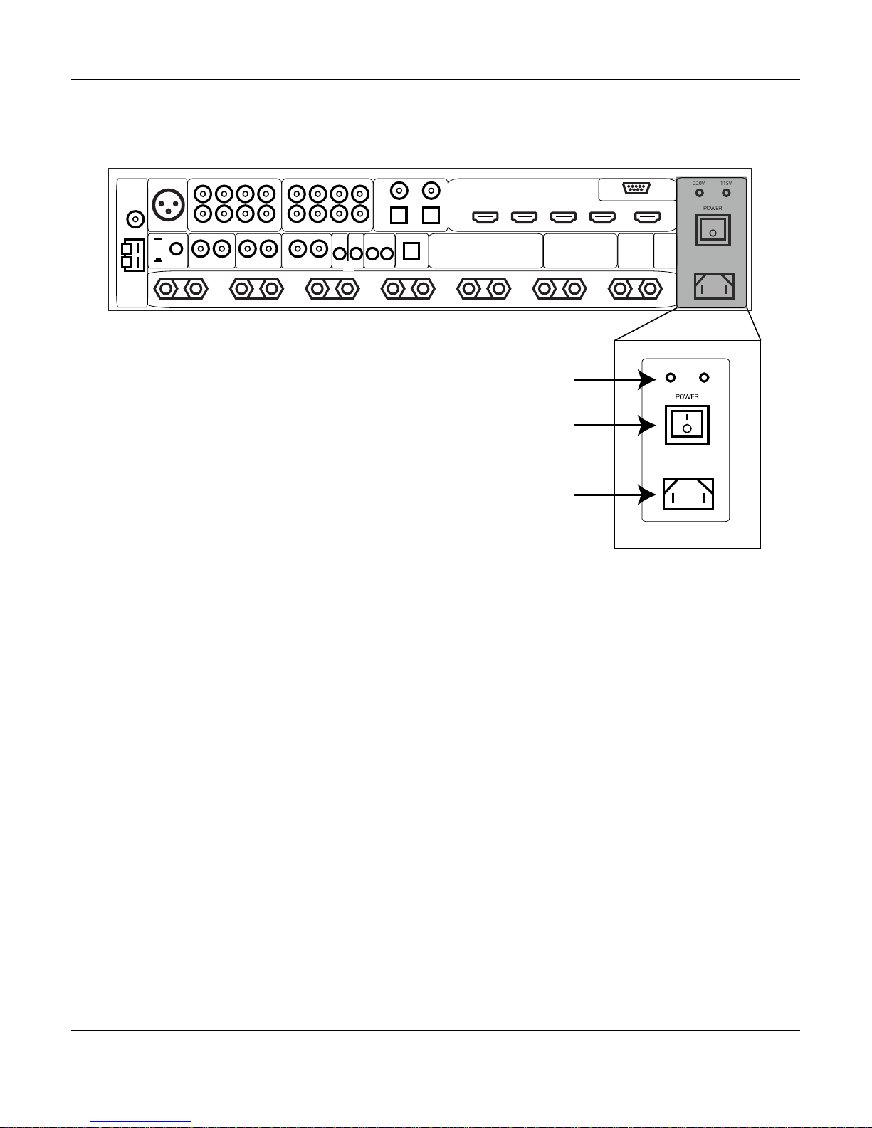
Rear Panel - Power Connections
1. Input Voltage Indicator
The SR-8100 automatically detects the correct AC line voltage. These LEDs indicate which voltage
has been detected.
2. Power Switch
Switches the AC main power to the SR-8100 On and Off. When this switch is Off, the SR-8100 will
not respond to trigger signals or manual controls.
3. Standard IEC Power Inlet
The SR-8100 can be used with either a two-wire or three-wire standard IEC power cable.
Page 10
SR-8100: User Manual
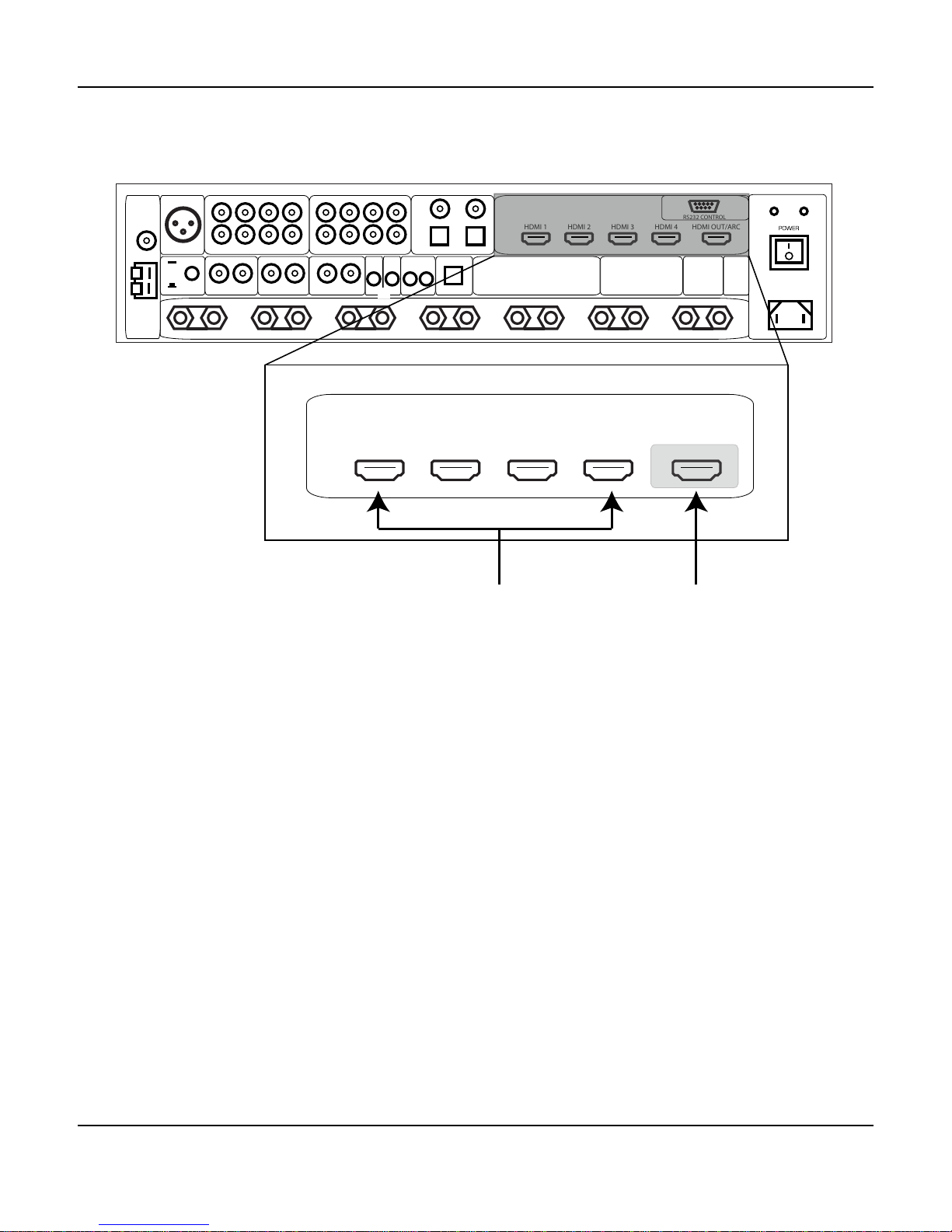
Rear Panel - Video Inputs and Outputs (HDMI)
1. HDMI Inputs (4)
Provide four inputs for components that have either HDMI or DVI-D outputs. (An appropriate
adapter will be required to connect DVI-D devices, and not all features will be available.) All four
HDMI inputs are identical, are HDMI 1.4 compatible, and support all standard formats (including 3D)
up to 1080p/24.
2. HDMI Output (1)
The HDMI output is HDMI 1.4 compliant, and is ARC and CEC enabled.
1 2
HDMI 1 HDMI 2 HDMI 3 HDMI 4 HDMI OUT/ARC
HDMI 1 HDMI 2 HDMI 3 HDMI 4 HDMI OUT/ARC
AN 1 AN 2 AN 3 AN 4 FL SL CNT SBL
FR SR SUB SBR
SUB OUT STEREO IN 7.1 ANALOG IN DIGITAL IN
CO 1 CO 2
OPT1 OPT2
L R L R L R
L
R
SBL/SBR
ZONE 2
BACK CHNL MIX ZONE 2 ZONE 3 IR TRIGGER OUT USB
IN OUT 1 2
FM
AM
220V 115V
RS232 CONTROL
SBL SL FL CNT FR SR SBR
7.1 OUT
ANTENNAS

Page 11
SR-8100: User Manual
Rear Panel - Audio Inputs (Analog and Digital)
HDMI 1 HDMI 2 HDMI 3 HDMI 4 HDMI OUT/ARC
AN 1 AN 2 AN 3 AN 4 FL SL CNT SBL
FR SR SUB SBR
SUB OUT STEREO IN 7.1 ANALOG IN DIGITAL IN
CO 1 CO 2
OPT1 OPT2
L R L R L R
L
R
SBL/SBR
ZONE 2
BACK CHNL MIX ZONE 2 ZONE 3 IR TRIGGER OUT USB
IN OUT 1 2
FM
AM
220V 115V
RS232 CONTROL
SBL SL FL CNT FR SR SBR
7.1 OUT
ANTENNAS
AN 1 AN 2 AN 3 AN 4 FL SL CNT SBL
FR SR SUB SBR
STEREO IN 7.1 ANALOG IN DIGITAL IN
CO 1 CO 2
OPT1 OPT2
L
R
1 2 3
1. Stereo Unbalanced Analog Audio Inputs (4 pairs)
Provide inputs for four unbalanced stereo analog sources.
2. 7.1 Unbalanced Analog Audio Inputs (1 set)
Provides one set of unbalanced 7.1 channel surround audio inputs. The signals received at these
inputs bypass all digital processing and are passed directly to the volume control and the preamp
outputs. Typically, the analog surround sound outputs of an SACD player or external decoder are
connected to these inputs.
3. Digital Audio Inputs
The SR-8100 provides four digital audio inputs. CO 1 and CO 2 are for standard Coaxial connectors
carrying S/PDIF digital audio; OPT 1 and OPT 2 are for standard Toslink optical cables carrying
optical S/PDIF digital audio.
Note: The USB input is only for use in applying rmware updates.

Page 12
SR-8100: User Manual
Rear Panel - Main Audio Outputs (Analog)
1. Subwoofer Output (balanced)
Connect this output to the balanced input of a powered subwoofer.
(An unbalanced subwoofer may be connected using the included XLR-to-RCA adapter.)
2. Speaker Outputs (7)
Connect up to seven 4 ohm or 8 ohm speakers to these outputs.
Note: The SR-8100 can be congured for either 5.1 or 7.1 surround sound operation.
If you congure the SR-8100 for 5.1 channel operation, use the FL, FR, CNT, SL, and SR
speaker outputs (and NOT the SBL and SBR outputs).
Note: These speaker outputs can also be congured as Front Left and Front Right Height
Speakers, or as Bi-Amped outputs for the front speakers.
Note: The SBL and SBR Speaker Outputs may be congured to run as a stereo pair of
speakers operated by Zone 2 (see the Zone Audio Outputs section for details).
2
7.1 OUT
SBL SL FL CNT FR SR SBR
SUB OUT
HDMI 1 HDMI 2 HDMI 3 HDMI 4 HDMI OUT/ARC
AN 1 AN 2 AN 3 AN 4 FL SL CNT SBL
FR SR SUB SBR
SUB OUT STEREO IN 7.1 ANALOG IN DIGITAL IN
CO 1 CO 2
OPT1 OPT2
L R L R L R
L
R
SBL/SBR
ZONE 2
BACK CHNL MIX ZONE 2 ZONE 3 IR TRIGGER OUT USB
IN OUT 1 2
FM
AM
220V 115V
RS232 CONTROL
SBL SL FL CNT FR SR SBR
7.1 OUT
ANTENNAS
1

Page 13
SR-8100: User Manual
Rear Panel - Zone and Mix Audio Outputs (Analog)
1. SBL/SBR Speaker Function Switch
When this button is pressed in, the speakers connected to the SBL and SBR speaker terminals
will act as Surround Back Left and Surround Back Right speakers (or as Front Left and Front Right
Height Speakers, or as Front Bi-Amp outputs, depending on how they are congured). When this
button is out, the speakers connected to the SBL and SBR speaker terminals will act as stereo
speakers for Zone 2. (This button setting overrides any other conguration settings.)
2. Mix Output
Provides a stereo unbalanced analog output that is the stereo mixdown of the surround sound
source currently playing in the main zone. The Mix Output is variable, and is controlled by the Main
Zone Volume setting.
3., 4. Zone 2 and Zone 3 Outputs
Provide stereo unbalanced line level analog audio outputs for Zone 2 and Zone 3.
1 2 3 4
L R L R L R
SBL/SBR
ZONE 2
BACK CHNL MIX ZONE 2 ZONE 3
HDMI 1 HDMI 2 HDMI 3 HDMI 4 HDMI OUT/ARC
AN 1 AN 2 AN 3 AN 4 FL SL CNT SBL
FR SR SUB SBR
SUB OUT STEREO IN 7.1 ANALOG IN DIGITAL IN
CO 1 CO 2
OPT1 OPT2
L R L R L R
L
R
SBL/SBR
ZONE 2
BACK CHNL MIX ZONE 2 ZONE 3 IR TRIGGER OUT USB
IN OUT 1 2
FM
AM
220V 115V
RS232 CONTROL
SBL SL FL CNT FR SR SBR
7.1 OUT
ANTENNAS

Page 14
SR-8100: User Manual
Remote Control
1ON
DIRECT STEREO MODE MODE
+ -
TV HDMI 1 HDMI 2
HDMI 3 HDMI 4 B
ON/OFF FREQ+ CH+
AM/FM FREQ- CH -
SUBTITLE AUDIO
B SUR SUR SUB CTR
+ Z2 +
- Z3 -
INPUT VOL
MENU
EXIT
ENTER
RETURN
MUTE
DIM
DISPLAY
8
10
7
11
6
5
8
4
3
2
17
16
15
13
12
9
14
CEC
PTR-101
1. Standby Button
Press this button when the SR-8100 is On to return it
to Standby Mode.
2. Mode Buttons
Press the Direct and Stereo Mode Buttons to switch
the SR-8100 directly into those audio modes. Press
the Mode + and Mode - Buttons to step through the
valid surround sound decoding modes available for
the input that is currently selected. (The modes you
can choose from will depend on the signal being
received at the input.)
Note: When playing DVD and Blu-Ray discs,
your player and the disc itself will probably offer
you a choice of several audio modes. After you
select one, the SR-8100 will determine which
type of audio is being supplied by your source
component, and will ONLY allow you to choose
audio modes that are compatible with that input
signal. (For example, if you select
“Dolby Digital” when playing a disc, the SR-8100
will offer you digital surround options compatible
with that mode, but NOT modes which are not
compatible with it.)
3. Direct Input Selector Buttons
Press one of the Direct Input Selector Buttons to
switch the SR-8100 directly to that input. The button
with the “B” symbol is used to select a Bluetooth
wireless device.
4. Tuner Control Buttons
Press the Tuner On/Off Button to switch directly to the
Tuner as your selected input; press it again to return
to your previously selected input. Use the AM/FM
Button to switch between the AM and FM bands. The
Freq+ and Freq- buttons change between different
AM or FM stations, and the CH+ and CH- buttons
step between any station presets you have created
(station presets are created in the Tuner Setup
menu).

Page 15
SR-8100: User Manual
5., 8. Return and Exit Navigation Buttons
Used to exit a screen or move up a level in some menus. (Refer to the hints along the bottom of the
OSD if you’re not sure which button to use in a given situation.)
6., 14. Enter Navigation Button and Navigation Ring
Use the Enter Button, and the Up, Down, Left, and Right controls on the Navigation Ring for
navigating the front panel and on-screen menus.
7. Display Button
Press this button to toggle the front panel display between displaying information about which input
is selected and displaying the current audio and video modes.
9. Input + and Input - Buttons
Press these buttons to step through the available inputs on your SR-8100.
10. Speaker Level Trim Controls
Use these buttons to temporarily adjust the levels of your various surround speakers. The changes
you make with these controls will not be retained when you turn the SR-8100 Off. You can
separately adjust the levels of the Center Channel, the Surrounds, the Back Surrounds, and the
Subwoofer with these controls.
11. CEC Control Buttons
These buttons are used to send commands from the SR-8100 to other CEC-enabled devices which
are connected to it. Various CEC-enabled devices will respond to some or all of these command
buttons when they are the selected input device. (You may also need to enable this feature on the
source device.) Please refer to the instructions that came with each device for details.
12. Menu Button
Accesses the front panel menu system and the full-color on-screen display (OSD).
13. Dim Button
Press this button to dim the front panel VFD (vacuum uorescent display) on the SR-8100. The
display will get gradually brighter each time you press the button, then, when it reaches the brightest
setting, drop back to the dimmest setting (dim but not fully off).
15. Mute Button
Press this button to mute the audio output of the SR-8100; press it again to return to the previous
Volume level.
16. Volume Buttons
Press these buttons to turn the volume up or down on the SR-8100. The current volume setting is
displayed on the front panel display.
Table of contents


