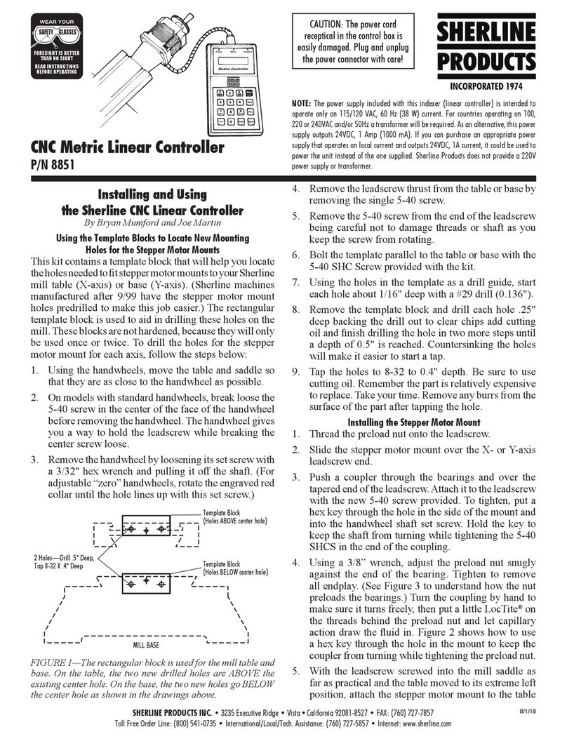
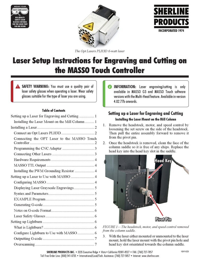
Sherline Products MASSO 8781 Installation and maintenance instructions

SHERLINE PRODUCTS INC. •3235 Executive Ridge •Vista •California 92081-8527 •FAX: (760) 727-7857
Toll Free Order Line: (800) 541-0735 •International/Local/Tech. Assistance: (760) 727-5857 •Internet: www.sherline.com
Sherline/MASSO Controller
Initial Start
11/20/19
WHAT’S INCLUDED
Shown here is what comes with the Sherline/MASSO Controller for our mill package.
A lathe package will be similar except that it will have two limit switches instead
of three, and different mounting hardware.
Assembling Your System
Mill orLathe: Unpackand assemble your machine according
to the instructions included in the Sherline Assembly and
Instruction Guide packed with the your new machine.
UnpacktheP/N8760driverboxandtheP/N8781Sherline/
MASSO controller box.
Set the driver box on your table rst, then set the controller
box on top of the driver box.
FIGURE 2—Front view of the controller box and the driver box.
Connect the white X, Y, and Z stepper motor cables leading
from the back of the driver box to each of the stepper motor
connectors. The axis that the cables will control are laser
engraved on the driver box (see Figure 3).Afourth cable is
unused unless you have purchased an optional CNC rotary
table, which can be connected here as a 4th (A) axis.
Sherline/MASSO CNC Controller Initial Start Instructions
Clockwise, from upper right
1. Controller box
2. 4-axis CNC driver box*
3. Wifi antenna
4. Parallel cable
5. Limit switch main cable bundle
6. USB 4 GB flash drive
7. Limit switches (with pigtail and connector)
8. Speed control cable
9. P/N 68047 Plastic plug for speed control housing
10. Tach/spindle control cable bundle
11. Optical encoder
12. Tach gap setter and cover
13. Tach spindle pulley RPM sticker
14. Tach bracket and headstock spacer (standard or 3C)
15. Ball screw mill headstock cable support (zip ties for leadscrew mills)
* NOTE: P/N 8780 includes the driver box. P/N 8781 does not include the driver box.
CAUTION—Protect your motors, cables, and driver board!
• Never connect or disconnect the optical encoder grounding cable or
the stepper motor cables with the Controller/Drive box power on.
•Do not unplug stepper motors using the rectangular white plug that
goes into the motor. Disconnect only at the cable plug.
•Do not pull on cable wires to disconnect plug—grip at connector.
• Turn handwheels slowly (1 rev/sec) with driver power OFF when
manually positioning. For longer travels use Jog Mode.
FIGURE 1—Back view of the controller box and the driver box
CUSTOMER FEEDBACK REQUEST
Afteryouhaveread alltheinstructionsand watchedallthehow-to videos,pleasefeel
freetosendusanyfeedbackso wecanimproveourMASSOcontrollerdocumentation.
1
2
3
6
7
4
8
12
11
10
13
5
14
15
9

Sherline/MASSO Controller
Initial Start
Page 2 OF 22
FIGURE 3—Each axis is laser engraved above the cable ports.
Plug in the limit switch connector, the encoder/spindle
connector, and the 24VDC power supply cable into the
backside of the controller box.
FIGURE 4—Encoder/Spindle drive cable P/N 87820
FIGURE 5—Limit Switch Cable P/N 87825
FIGURE 6—Backside of control box.
The controller and the drive box only need one power
supply. When you look at the front of the controller box
you will see the 24VDC power out connector. Plug it into
the power in connector on the drive box.
FIGURE7—Powerconnectorcablepluggedintothedriverbox.
Now take the parallel port cable P/N 87605 and plug the
female end into the driver box.
FIGURE 8— Female end of the parallel cable.

Sherline/MASSO Controller
Initial Start
Page 3 OF 22
Now plug the male end of the parallel cable into the
controller box.
FIGURE 9—Male end of the parallel cable.
FIGURE 10—The parallel cable shown plugged into both the
driver box and the controller box.
Plug your monitor cable into the monitor port (see Figure
11). The monitor port is set up for a VGA connector. If you
have an HDMI connection on your monitor, you will need
to buy a VGA-to-HDMI converter* (see Figure 12 for an
example). You can pick these up on eBay, Amazon, or at
your local electronics supplier, and most are inexpensive.
*NOTE: Make sure you purchase a VGA-to-HDMI
converter. There are many HDMI-to-VGA connectors out
there and they will not display the VGA video output signal
to your HDMI monitor.
FIGURE11—Monitorconnection.TheVGAconnectorisplugged
into the monitor port on the controller box.
FIGURE 12—Shows an example of a VGA-to-HDMI converter.
Please note that some VGA-to-HDMI converters require a USB
powered connection.
Now plug your USB dongle for your wireless mouse and
keyboard into the AUX USB connection*. You cannot use
a multi-port USB hub connector in either of the USB ports
to operate your old, USB-wired mouse and keyboard. The
software is designed to take single-source information only
from each of the USB ports. A multi-port connector will
not work. You must use a wireless USB dongle for your
peripherals.
*NOTE: We do not supply the wireless mouse, keyboard,
or dongle. There is only one USB port for your mouse
and keyboard. Make sure you buy a wireless mouse and
keyboard set.
FIGURE13—Left:close-upoftheUSBdongle;Right:thedongle
plugged into the AUX USB port.

Sherline/MASSO Controller
Initial Start
Page 4 OF 22
Now plug in your ash drive with your machine settings,
tool settings, and programs into the Program USB
connection.
FIGURE 14—Left: close-up of the Sherline 4 GB USB ash
drive; Right: the ash drive plugged into the Program USB port.
Connecting the Cables to Your Machine
Now that all ofyour cables are hooked up tothe control and
driver boxes, it’s time to connect them to your machine.
NOTE: Make sure that all power is o on the controller
and drive box before proceeding.
First we will install the headstock cable support P/N 87840.
This cable support is easy to install. It has two slots that
go onto the two 10-32 screws that hold the motor mount
to the headstock.
NOTE: This bracket is not included for “leadscrew
machines” (only ball screw machines). See instructions for
leadscrew machines at the end of this document.
FIGURE 15—P/N 87840 mill headstock cable support.
Loosen these two 10-32 screws about three turns.
FIGURE 16—The red arrows indicate the screw locations.
This should give you a large enough gap between the
motor bracket and the headstock for the cable support to
t in easily.
FIGURE 17—The photo above shows the gap between the
headstock and the mounting bracket.
Now position the cable support so the slotted side can be
positioned onto the 10-32 screws between the motor mount
and the headstock.
FIGURE 18—The red arrows show how the slots on the cable
support align to the 10-32 screws on the headstock mounting
bracket.

Sherline/MASSO Controller
Initial Start
Page 5 OF 22
Now push the cable support into place. Once the cable
support is in place, tighten the two 10-32 screws in order
to clamp the cable support between the motor mount and
the headstock.
At this point just tighten the top screw all the way, and leave
the bottom screwalone. We will beattaching the grounding
cable from the encoder cable to the bottom screw.
FIGURE 19
Below is a picture of the end of the encoder cable with the
black grounding cable.
FIGURE 20—The black grounding cable is above the encoder
cable.
Place the encoder cable on top of the column saddle
assembly with the grounding cable hanging inside of the
cable support (see Figure 21).
FIGURE21—Noticethatthegroundingcableisinsidethesupport
toward the front of the machine.
CAUTION
Any time that you connect or disconnect the grounding cable,
all power to the machine and the Controller/Drive boxes must
be off.
Failure to do so may result in a ground fault that will severely
damage the Optical Encoder.
Now push the spade connector on the end of the grounding
cable onto the 10-32 screw and between the washer and
the motor bracket.
FIGURE 22—Make sure the spade connector is located behind
the washer. The inset photos shows an alternate location for the
grounding wire on the opposite side of the headstock.

Sherline/MASSO Controller
Initial Start
Page 6 OF 22
Make sure that the spade connector is straight up and down
so it sits in the middleof the motorbracket.Also be sure that
the washer is not clamping on the insulation of the spade
connector, but directly on the metal area of the connector.
Then tighten the bottom 10-32 screw (see Figure 23).
FIGURE 23—The orientation of the grounding wire is straight
up and down.
Now that the grounding cable is mounted, we can power
up the controller. You will need access to the Setup page
on the controller in order to adjust your limit switches.
Flip the power toggle switch on the controller up, and you
should see the green power light come on.
FIGURE 24—The white arrow shows the on/o controller switch.
Now ip the power toggle switch on the driver box up, and
you should see the red power light come on.
FIGURE 25—The black arrow shows the on/o driver box switch.
When your monitor comes on, you will see the control page
below. The yellow Home icon will be ashing. The red
E-Stop icon will be ashing, and the password box will be on.
FIGURE 26—The white arrows point to the “HOME,” and
“E-STOP,” buttons.
First turn the E-stop button clockwise on the top of the
controller box to deactivate it. If you didn’t use the E-Stop
button to turn the machine o when you last used it, you
will need to push the button down to activate it rst, and
the turn it to deactivate it.
FIGURE 27—Note the clockwise direction of the arrows on the
red button.
When you deactivate the E-Stop button, the red ashing
E-Stop icon will stop blinking.
FIGURE 28—The E-stop button stops ashing red.

Sherline/MASSO Controller
Initial Start
Page 7 OF 22
Now enter the password [ SP] into the password box. The
[SP] must be ALL CAPS.
FIGURE 29
At this point you would normally home out your machine.
Instead of homing the machine, we are going to go to the
Setup page so you can see the input signals from your
encoder and your limit switches.
FIGURE 30—At the bottom left-hand corner, you will see the
“F1 Setup,” button. Click on it and the setup page will come up.
Mounting Instructions for the Encoder
Tach Decal for the Optical Encoder
First, place the Tach/Encoder sticker on the headstock
pulley.
Remove any dirt, oil, or grease from the mounting surface
of the pulley. You can use rubbing alcohol on a clean cloth
or paper towel.
FIGURE 31—Clean the spindle pulley surface before placing
the tach/encoder decal.
FIGURE 32—Tach/Encoder sticker P/N 68060.
The center hole on the sticker is made to t our standard
headstock pulley. If you are placing the sticker on one of
our 3C headstocks, you will need to cut out the center on
the line shown below.
FIGURE 33—The red arrow indicates the 3C spindle diameter.
Peel o the paper backing on the sticker. Then align the
sticker on the end of the spindle and lower it down onto the
pulley. If you bow the sticker slightly so the center is lower
than the outer edge, you can use the spindle to locate the
sticker. Then lower it down until the center makes contact
with the pulley area near the spindle. The location doesn’t
need to be perfect and you should be able to get it close
enough by centering it around the spindle. Once the center
has made contact with the pulley, check your centering
before there is too much surface contact and make minor
adjustments. Nowlower therestof thesticker ontothe pulley.
The outer edge should be centered with the outer edge of
the pulley as well. Now press down on the sticker with your
ngers at the center and then rub from the inside outward to
remove any bubbles or imperfections. The sticker has to be
at or it will interfere with the encoder readings.
Optical Encoder
Next we will mount, adjust, and connect the optical encoder
to the headstock.
We are mounting this encoder on one of our standard

Sherline/MASSO Controller
Initial Start
Page 8 OF 22
headstocks. The parts and the procedures are the same
for our 3C headstock with the exception of the encoder
spacer block. For thestandard headstock we use spacerP/N
87816 and mounting screws P/N 40720 (10-32 x 1-1/2"
SHCS). For the 3C headstock we use spacer P/N 87817
and mounting screws P/N 40340 (10-32 x 1" SHCS).
1
23
4
5
6
7
8
FIGURE 34—Encoder parts, clockwise from top right:
(1) P/N 87812 optical encoder cover
(2) P/N 87811 5-40 x 3/8" Phillips, button-head machine screw
(3) P/N 87810 optical encoder
(4) P/N 40530 5-40 X 3/8" SHC Screws (2 ea.)
(5) P/N 87813 .129 optical encoder gauge
(6) P/N 87816 optical encoder spacer for standard headstock*
P/N 87817 optical encoder spacer for 3C headstock**
(7) P/N 87814 optical encoder bracket
(8) P/N 40720* 10-32 x 1-1/2" SHC Screws and P/N 40660
#10 washers (2 ea.) for standard headstock spacer
P/N 40340** 10-32 x 1" SHC Screws and P/N 40660 #10
washers (2 ea.) for 3C headstock spacer
Optical encoder mount, spacer, and mounting screw
assembly (see Figure 35).
FIGURE 35—Left: side view; Right: end view.
Mounting the Optical Encoder
The power switch on the speed control must be in the
off position when the spindle is not in use.
Notice the tapered sides of the mounting bracket and the
two lines on the mating surface of the encoder.Any contact
with the encoder must be between the two white lines (see
Figure 36).
FIGURE 36—The arrows point to the two white lines on the
encoder surface.
FIGURE 37—Full assembly side view: The screws are just in
place for show. Nothing is tightened at this point.

Sherline/MASSO Controller
Initial Start
Page 9 OF 22
You may need to drill and tap the 10-32 holes on your
headstock to mount the optical encoder. If this is the case,
please go to the page 20 of this document for the Optical
Encoder Mounting Template Instructions.
FIGURE 38—Mounting hole locations on the headstock. Use
the template at the end of this document to drill and tap the
mounting holes.
The encoder assembly is mounted to the headstock (see
Figure 39), with the 10-32 screws just snug, so we can
adjust the encoder bracket to get the encoder gap set (see
Figure 40).
FIGURE 39
FIGURE 40—Encoder Gap Gauge P/N 87813.
FIGURE 41—Gap gauge placement.
With the two 10-32 bracket mounting screws loose, lower
the optical encoder down until it makes contact with the
gap gauge. Make sure that the screws are loose enough so
the optical encoder body is not exing when you lower it
into position.
Once the encoder is touching the gap gauge, put pressure
on the top of it with your nger (see Figure 42).
While pressing on the encoder, tighten the two 10-32
bracket mounting screws.

Sherline/MASSO Controller
Initial Start
Page 10 OF 22
FIGURE 42—With the gap gauge in place, apply pressure on
top of the encoder.
There will generally be some space between the encoder
and the gap gauge after you tighten the screws. This is
ne. The gap gauge is set to the middle of the LED focal
point length (.129" or 3.27 mm). Therefore, if the encoder
is slightly higher or lower than the gap gauge, it will still
be in tolerance.
Once the screws are tight, remove the gap gauge.
FIGURE 43—The red arrow shows the gap between the pulley
and the LED sensors.
FIGURE44—ShowstheLEDlightsontheencoderwiththepower
connection plugged in (Just for show). Remover the connection
until the cover is in place.
Now we are going to mount the encoder cover.
First a special note: The primary reason for the cover is
to help avoid any damage to the encoder and also to keep
oil and machine debris o of it. The second reason (which
we found out the hard way) is to avoid exterior LED light
interference with the LEDs that are on the encoder. If your
machine is in an area that has uorescent lighting, then
exterior light interference will not be a problem. However,
if you are using LED lights around your machine, such as
overhead energy saving LED lights. The exterior LED light
will bounce o of the tach/encoder sticker and cause the
encoder to receive bad light readings and send inaccurate
signals to the controller. This will cause erratic RPM and
cross threading on the lathe threading cycle.
If the encoder is positioned correctly, you will see the
signals coming into the setup page.
Click on the F1 Setup button on the lower left corner of
the screen. If you double click on the password box and
then click on the setup page, the password box will close.
A
Zero
B
FIGURE 45—On the tach sticker, the black and white sections
on the outer ring are for the A and B signals. The solitary black
section in the center area is for the Index signal.
CAUTION
Do not connect or disconnect the optical encoder connector or
the ground wire with the power on or you will do irreparable
damage to the optical encoder!

Sherline/MASSO Controller
Initial Start
Page 11 OF 22
If you turn the spindle pulley by hand starting with the
index point under the encoder, the signals will come into
the setup page. See the signal sequence below.
FIGURE 46—Starting between the index point and position 1,
the status for A, B, and Index will be Low.
FIGURE47—Turningthepulleyslowly,Signal-AwillturntoHigh.
FIGURE 48—Continue to turn and Signal-B will turn to High.
FIGURE49—Continueto turnandSignal-Awillchange to Low.
FIGURE 50—Then Signal-B will change to Low.
The inputs will follow this sequence from position 1
through position 4.
FIGURE 51—When you get to position 5 for the index point,
rst Signal-A will change to High, then Index Position 5 will
change to High.
FIGURE 52—Then Signal-B will change to High so all three
Inputs are showing High.
Then Signal-A will change to Low, Index Position 5 will
change to Low and then position B will change to Low.
NOTE: If you are not getting these readings, try shading
the encoder and the tach sticker with a piece of cardboard
to eliminate any outside light source. Then turn the spindle
again.

Sherline/MASSO Controller
Initial Start
Page 12 OF 22
FIGURE 53—Placement of encoder cover P/N 87812.
There must be a gap between the front edge of the cover
and the tach/encoder sticker so it doesn’t rub on the sticker.
FIGURE 54—The red arrows indicate the gap between the
encoder cover and the tach/encoder sticker.
NOTE: The gap is approximately .020"-.050" (.50 – 1.27mm).
Tighten the mounting screw snug. Then readjust the cover
so there is still a gap between the cove and the pulley.
FIGURE 55—Encoder cover mounting screw P/N 87811 5-40 x
3/8" Phillips, button-head machine screw.
FIGURE 56—The red arrows show the gap after nal adjustment.

Sherline/MASSO Controller
Initial Start
Page 13 OF 22
Turn the Spindle on and Check the Readout
For customers who are doing a retrot, see this video,
Speed Control Retrot for CNC Controller (https://youtu.
be/1zIAV6I4MBo), for instructions on how to wire the
speed control for the MASSO controller.
1. Flip the spindlecontrolpowerswitchtotheONposition.
FIGURE 57—The white arrow indicates the direction of the
“ON,” position.
2. Click on the “F2 Program & MDI,” button.
FIGURE 58—The F2 Program & MDI button should be
highlighted yellow.
3. Click on the blank box to the right of “Spindle CW.,”
FIGURE 59— The cursor arrow is over the blank box.
4. Type in 1000. Then hit enter.
5. Now click on the “Spindle CW,” button and the spindle
will turn on.
FIGURE60—Thecursorarrowisoverthe“SpindleCW,”button.
NOTE: Do not click on the “Spindle CCW,” button. Our
motors do not turn CCW. If you click on the CCW button,
the motor will hum and it may oscillate a bit, but it will
not turn CCW or CW. Click on “Spindle STOP,” and then
use “Spindle CW,” to start it.
6. The spindle RPM will uctuate a bit at rst, and then
they will settle down and bounce between 995 and 1008
RPM. You can see the actual RPM on the control page.
FIGURE 61
7. To turn o the spindle, click on the yellow “Spindle
STOP,” button.
FIGURE 62
If your RPM are incorrect, or if they are fluctuating
excessively, make sure that the encoder cover is on and
positioned correctly. If the RPM are still o, reset your
encoder gap.

Sherline/MASSO Controller
Initial Start
Page 14 OF 22
Mounting and Adjusting the Limit Switches
Y-axis Limit Switch and Eccentric Trigger
1
2
3
4
5
6
FIGURE63—Y-axislimitswitchparts,clockwisefromtopright:
(1) P/N 68040 limit switch w/pigtail
(2) P/N 68024 Y-axis limit switch mount
(3) P/N 68046 Limit switch mounting tab
(4) P/N 68049 #2 Phillips x 5/8" at-head sheet metal screws (2 ea.)
(5) P/N 67115 5-40 x 7/8" SHC screws (2 ea.)
(6) P/N 87841: 1/8" x 1-1/2" steel transfer punch for mill Y-axis
limit switch (Retro)
(7) Zip ties
Figure 64 shows the limit switch positioning on the Y-axis
mount: Limit switch P/N 68040, Mounting screws P/N
68048, and Y-axis mounting bracket P/N 68024.
FIGURE 64—The mounting screws are used to attach the limit
switch to the Y-axis limit switch mount.
FIGURE 65—Backside view of the Y-axis limit switch assembly.
FIGURE66—Y-axislimitswitchassemblywiththebackingplate
P/N 68046 attached.
FIGURE 67—Front side view.
FIGURE68—The redoval showsthemounting holelocation for
the Y-axis limit switch assembly.*
*NOTE: If you are doing a retrot, see the Limit Switch
Hole Templates for the Y and Z-axes on page 21.
You can also watch our YouTube video, Mill Base Limit
Switch Retrot, for how to drill and tap these mounting
holes. (https://youtu.be/8-BOprooqIQ)

Sherline/MASSO Controller
Initial Start
Page 15 OF 22
FIGURE 69—The limit switch mounted the with wires going
between the mounting bracket and the mill base.
The Eccentric Trigger Assembly and Mounting
Eccentric trigger parts.
FIGURE70—Left:10-32x1"SHCSP/N40340,eccentrictrigger
P/N 68039, and nylon spacer P/N 68044; Right: Assembly
FIGURE 71a—The red oval shows the location of the eccentric
trigger mounting hole on the ball screw saddle.
FIGURE71b—Left:Onastandardleadscrewmachine,youwill
removetheY-axislockingscrew;Right:Theninstalltheeccentric
trigger where the Y-axis locking screw was.
FIGURE 72—Mount the assembly with the wide side of the
eccentric trigger facing down.
At this point the 10-32 screw on the eccentric trigger and
the two screws that secure the limit switch are snug on the
verge of being loose, so the trigger and the limit switch
can be adjusted.
First turn the driver box power “O,” and then disconnect
the Y-axis stepper motor cable (NOTE: Never disconnect
or connect the stepper motor cables with the power on).
Now by hand, move the Y-axis towards the stepper motor
until the Y-axis accordion cover is almost fully closed
(you want to leave some room for the inevitable chip
build-up). You also need some extra room for the slight
over-travel when the trigger sets the limit switch (about
.100" or 2.54 mm).
Now open the F1 SETUPscreen on the controller (push F1
or click on the F1 Setup button on the screen).
FIGURE 73—Setup screen with password box.

Sherline/MASSO Controller
Initial Start
Page 16 OF 22
You don’t need the password to see the input and output
status of your limit switches and your encoder signal. If
the password box is in the way, click on it a couple times
and then click on the screen once and it will close.
Make sure that your limit switch connector is plugged into
the control harness.
In the middle of the setup screen towards the bottom, you
will see the “X, Y, Z, and A-Home Sensor Input.,” When
the limit switch is plugged in, and in the open position, the
Status column will be “green – Low,” (see picture).
FIGURE 74—Home sensor screen for limit switches.
With your Y-axis in the home position, adjust the limit
switch and the eccentric trigger so the limit switch closes
at that point. You can hear the limit switch click when it
closes.
FIGURE 75—Home position for the Y-axis.
When you believe that your limit switch is set correctly,
manually move the Y-axis o of the limit switch. Then
look at the setup page. Now move the Y-axis back slowly
and when the limit switch closes, the “green – low,” on the
status will change to “red – High.,”
FIGURE 76—Red=High status.
By looking at the status on the setup screen and moving
the Y-axis back and forth, you can adjust the limit switch
and the eccentric so the limit switch closes at the desired
position. Once the position is set, tighten the two limit
switch screws and the 10-32 eccentric trigger screw.
Z-axis Limit Switch and Eccentric Trigger
The Z-axis and the X-axis are easier to mount and adjust.
For these instructions weare mounting these limit switches
on a ball screw machine. The mounting brackets will be
dierent on a leadscrew machine.
Z-axis switch, mount, and screws.
1
2
6
54
3
FIGURE 77—Z-axis limit switch parts, clockwise from top:
(1) P/N 68020 Z-axis limit switch mount
(2) P/N 68042 Eccentric trigger
(3) P/N 12050 8-32 x 3/8" SHCS
(4) P/N 68040 Limit switch
(5) P/N 68048 #2 Phillips x 1/2" at-head sheet metal screws (2 ea.)
(6) P/N 68046 Limit switch mounting tab
(7) Zip ties

Sherline/MASSO Controller
Initial Start
Page 17 OF 22
FIGURE 78—Limit switch mounted to the Z-axis limit switch
mount.
FIGURE 79—#1: The red ovals indicate the mounting screws
from the stepper motors for the limit switch mounting bracket.
#2:This red oval shows the location of the screw hole on the mill
column saddle for the eccentric trigger.*
* NOTE: You may need to drill and tap the 8-32 hole on your
column saddle to mount the Z-axis eccentric trigger. If this is the
case, please go to page 21 of this document for the Limit Switch
Hole Templates for the Y and Z-axes.
FIGURE 80—Mount the eccentric trigger on the column saddle
and leave it loose.
FIGURE 81—Install the Z-axis limit switch mounting bracket
using the two 8-32 screws from the stepper motor.

Sherline/MASSO Controller
Initial Start
Page 18 OF 22
Once the limit switch is mounted, turn o the driver box
and then disconnect the power cord to the stepper motor.
Now raise thecolumn saddle all the wayto the top of travel.
Then lower the column saddle one full revolution of the
handwheel. This is where you want to set your limit switch
“closed position.”Adjust the eccentric and the limit switch
for the Z-axis the same way that you did for the Y-axis.
Once the position is set, tighten all of your screws.
FIGURE 82—Final Z-axis limit switch position.
X-axis Limit Switch Setting and Eccentric Trigger
X-axis limit switch parts.
1
2
3
4
5
FIGURE83—X-axislimitswitchparts,clockwisefromtopright:
(1) P/N 68040 limit switch w/pigtail
(2) P/N 81270 2-56 x 3/8" Phillips head machine screws (2 ea.)
(3) P/N 40510 10-32 x 3/8" SHC screw
(4) P/N 12050 8-32 x 3/8" SHC screws (2 ea.)
(5) P/N 68026 X-axis limit switch mount
(6) Zip ties
FIGURE 84—X-axis mounting holes:
#1: 10-32 screw for the eccentric trigger.
#2: 8-32 screws for the limit switch mounting bracket.
FIGURE85—Thread in the10-32x 3/8" SHCSintothe side hole
on the saddle. If there is a set screw in this hole, remove it rst,
then thread in the 10-32.
FIGURE 86—Attach the X-axis limit switch mounting bracket,
P/N 68026, using the two 8-32 screws.

Sherline/MASSO Controller
Initial Start
Page 19 OF 22
FIGURE87—Mountthelimitswitchwiththespringrollerfacing
own using the two 2-56 screws P/N 81270.
The alignment of the limit switch and the 10-32 screw is
ne just the way it is. No adjustments needed.
Plug in the limit switch to the main cable connector for
the X-axis.
Go to the setup page.
Move the table byhand until the limit switchmakes contact
with the 10-32 screw. Slowly continue to move the table
towards the saddle and look for the “Low Green,” status to
turn to “High Red,” when the limit switch closes.
For each axis, use a small zip tie and secure the limit switch
pigtail to the stepper motor cable (see pictures below).
FIGURE 88—Limit switch axes connections.
Left: X-axis; Middle: Y-axis; Right: Z-axis
Trim the Zip Ties.
FIGURE 89—Use wire cutters to trim o the excess zip tie ush at
the knuckle. Exposed zip tie ends will cut you, so trim them ush.
Now We Can Home out the Machine
With the control box and driver box both on, and the E-stop
triggered, and the password (SP) entered, press the Ctrl,
Alt, and Home buttons on your keyboard. All of your axes
will now home out on their respective limit switches. Each
axis will move until they make contact with their limit
switch, then the axis will stop, then it will move away from
the limit switch approximately one full revolution of the
leadscrew and stop. The setup les are set to home out the
Z-axis rst, then the Y-axis, and then the X-axis.
If you have an axis that does not home out correctly, check
to see if your limit switch connector is plugged in all the
way. If you are still having problems, call us for assistance
(760-727-5857).
Optical Encoder and Speed Control Wires
on Leadscrew Machines
For the leadscrew machine, we don’t supply a bracket for
the encoder and speed control cables. We supply zip ties.
1. Push the encoder cable up so it creates a loop that goes
above the end of the spindle pulley and allow enough
room to use the draw bolt on the end of the spindle.
Then zip tie the cable to the power cord that is coming
out of the motor (see Figure 90).
FIGURE 90

Sherline/MASSO Controller
Initial Start
Page 20 OF 22
2. Now zip tie the speed control cable and the encoder
cable to the power cord that is coming out of the speed
control (see Figures 91 and 92).
FIGURE 91—See the red arrow for the zip ite location.
FIGURE 92
3. We highly recommendusing the alternative groundwire
mounting location, so there will be one less wire going
over the spindle and pulley (see Figure 93).
FIGURE 93— The photo shows an alternate location for the
grounding wire on the opposite side of the headstock.
CAUTION
Always be sure to disconnect the power from the controller
before connecting or disconnecting the ground wire or the
optical encoder connection.
Failure to do so may result in a ground fault that will severely
damage the Optical Encoder.
Related Sherline Video Links
You can get further visual instructions on how to set up your
new Sherline/MASSO controller by going to our YouTube
channel, or by following the links below.
1. Setting up Your New Sherline CNC Controller
(This video shows you how to connect your controller
to your machine. It then goes on to show you how to
use the controller.)
https://youtu.be/obFdVI7K9bw
2. Setting up the Optical Encoder
(This video shows you how to mount your encoder, set
the gap, check the signals, and turn the spindle on for
the nal RPM check.)
https://youtu.be/ynfJ38QLMoE
Thank you,
Sherline Products Inc.
Other Sherline Products Controllers manuals
Popular Controllers manuals by other brands
Lenze
Lenze EPM-S900 Mounting instructions
Finnleo
Finnleo SaunaLogic SL2 Control manual
F.lli Scapin
F.lli Scapin GREEN POWER LINE Series quick start guide

Critical Environment Technologies
Critical Environment Technologies FCS-M Series Operation manual
DekunTech
DekunTech G2 Series instruction manual
Burkert
Burkert 3004 quick start
