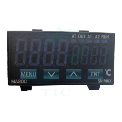
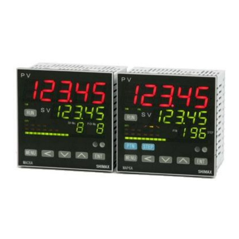
Shimax MAC5 Series User manual

1
11
1
MAC5 Series
MAC5 Series MAC5 Series
MAC5 Series
Digital Controller Instruction Manual
Digital Controller Instruction Manual Digital Controller Instruction Manual
Digital Controller Instruction Manual
Thank you for purchasing SHIMAX product.
Thank you for purchasing SHIMAX product. Thank you for purchasing SHIMAX product.
Thank you for purchasing SHIMAX product.
Please check that the product is the one you ordered.
Please check that the product is the one you ordered.Please check that the product is the one you ordered.
Please check that the product is the one you ordered.
Please operate after you read the instruction manual and fully understand it
Please operate after you read the instruction manual and fully understand itPlease operate after you read the instruction manual and fully understand it
Please operate after you read the instruction manual and fully understand it
「
「「
「Notice
NoticeNotice
Notice」
」」
」
Please ensure that this manual is given to the final user of the instrument
Please ensure that this manual is given to the final user of the instrumentPlease ensure that this manual is given to the final user of the instrument
Please ensure that this manual is given to the final user of the instrument.
Contents
ContentsContents
Contents
Preface
PrefacePreface
Preface
1.Matters regarding safety
1.Matters regarding safety1.Matters regarding safety
1.Matters regarding safety
2.Introduction
2.Introduction2.Introduction
2.Introduction
2
22
2-
--
-1.Check before use
1.Check before use1.Check before use
1.Check before use
2
22
2-
--
-2.Caution for use
2.Caution for use2.Caution for use
2.Caution for use
.Installation and wiring
.Installation and wiring.Installation and wiring
.Installation and wiring
3
33
3-
--
-1. Installation site (environmental conditions)
1. Installation site (environmental conditions)1. Installation site (environmental conditions)
1. Installation site (environmental conditions)
3
33
3-
--
-2. Mounting
2. Mounting2. Mounting
2. Mounting
3
33
3-
--
-3. E ternal dimension and panel cutout
3. E ternal dimension and panel cutout3. E ternal dimension and panel cutout
3. E ternal dimension and panel cutout
3
33
3-
--
-4. Wiring
4. Wiring4. Wiring
4. Wiring
3
33
3-
--
-5. Terminal arrangement diagram
5. Terminal arrangement diagram5. Terminal arrangement diagram
5. Terminal arrangement diagram
4. Description of front panel
4. Description of front panel4. Description of front panel
4. Description of front panel
4
44
4-
--
-1. Names of front panel.
1. Names of front panel.1. Names of front panel.
1. Names of front panel.
4
44
4-
--
-2. E planation of front panel section
2. E planation of front panel section2. E planation of front panel section
2. E planation of front panel section
5. Description of screens
5. Description of screens5. Description of screens
5. Description of screens
5
55
5-
--
-1. How to move to another screen
1. How to move to another screen1. How to move to another screen
1. How to move to another screen
5
55
5-
--
-2. Setting Method
2. Setting Method2. Setting Method
2. Setting Method
5
55
5-
--
-3. Power
3. Power3. Power
3. Power-
--
-on and initial screen display
on and initial screen displayon and initial screen display
on and initial screen display
5
55
5-
--
-4. Monitoring screen
4. Monitoring screen 4. Monitoring screen
4. Monitoring screen
6. Operating setting
6. Operating setting 6. Operating setting
6. Operating setting
7. MODE setting
7. MODE setting7. MODE setting
7. MODE setting
7
7 7
7-
--
-1 . MODE1 :Key lock and SV Limit setting
1 . MODE1 :Key lock and SV Limit setting1 . MODE1 :Key lock and SV Limit setting
1 . MODE1 :Key lock and SV Limit setting
7
77
7-
--
-2. MODE2: Scale and PV setting
2. MODE2: Scale and PV setting2. MODE2: Scale and PV setting
2. MODE2: Scale and PV setting
7
77
7-
--
-3. MODE3
3. MODE33. MODE3
3. MODE3-
--
-4:Out 1
4:Out 14:Out 1
4:Out 1-
--
-2 setting
2 setting2 setting
2 setting
7
77
7-
--
-4. MODE 5:Event setting
4. MODE 5:Event setting4. MODE 5:Event setting
4. MODE 5:Event setting
7
77
7-
--
-5 . MODE6:DI setting
5 . MODE6:DI setting5 . MODE6:DI setting
5 . MODE6:DI setting
7
77
7-
--
-6 .DI operation character table
6 .DI operation character table6 .DI operation character table
6 .DI operation character table
7
77
7-
--
-7 .Measuring range code table
7 .Measuring range code table7 .Measuring range code table
7 .Measuring range code table
8. Supplementary Explanation of Function
8. Supplementary Explanation of Function8. Supplementary Explanation of Function
8. Supplementary Explanation of Function
8
88
8-
--
-1 . Auto return function
1 . Auto return function1 . Auto return function
1 . Auto return function
8
88
8-
--
-2. Output Soft Start Function
2. Output Soft Start Function2. Output Soft Start Function
2. Output Soft Start Function
8
88
8-
--
-3. Event Selection Alarm Operation Figure
3. Event Selection Alarm Operation Figure3. Event Selection Alarm Operation Figure
3. Event Selection Alarm Operation Figure
8
88
8-
--
-4. AT (Auto Tuning)
4. AT (Auto Tuning)4. AT (Auto Tuning)
4. AT (Auto Tuning)
8
88
8-
--
-5 .Output
5 .Output5 .Output
5 .Output-
--
-characteristics figure
characteristics figurecharacteristics figure
characteristics figure
9. Trou le Shooting
9. Trou le Shooting9. Trou le Shooting
9. Trou le Shooting
9
99
9-
--
-1. Cause and Treatment of Main Defects
1. Cause and Treatment of Main Defects 1. Cause and Treatment of Main Defects
1. Cause and Treatment of Main Defects
9
99
9-
--
-2. Cause and Treatment of Error Display
2. Cause and Treatment of Error Display2. Cause and Treatment of Error Display
2. Cause and Treatment of Error Display
10. Specification
10. Specification10. Specification
10. Specification
11. General Specification
11. General Specification11. General Specification
11. General Specification

2
22
2
Preface
PrefacePreface
Preface
This instruction manual is intended for those who will be involved in wiring,
installation, operation and routine maintenance of the MAC5.
This manual describes the care, installation, wiring, function, and proper
procedures regarding the operation of MAC5.
Keep this manual on hand while using this device. Please follow the provided
guidance.
1.Matters regarding safety
For matters regarding safet , potential damage to equipment and/or facilities
and additional instructions are indicated as follows:
◎This mark indicates hazardous conditions that could cause injur or death
of personnel. Exercise extreme caution as indicated.
「
「「
「
WARNING」
」」
」
◎This mark indicates hazardous conditions that could cause damage to
equipment and/or facilities. Exercise extreme caution as indicated.
「
「 「
「
CAUTION」
」」
」
◎This mark indicates additional instructions and/or notes.
「NOTE」
「
「 「
「
WARNING」
」」
」
MAC5 is designed for controlling temperature, humidit , and other ph sical
subjects in general industrial facilities. It must not be used in an wa that
ma adversel affect safet , health, or working conditions.
「
「 「
「
CAUTION」
」」
」
To avoid damage to the connected equipment, facilities or the product itself
due to a fault of this instrument, safet countermeasures must be taken
before usage, such as proper installation of the fuse and the overheating
protection device. No warrant , expressed or implied, is valid in the case of
usage without having implemented proper safet countermeasures.
The mark on the plate affixed to the instrument:
On the terminal nameplate affixed to the case of our instrument, the
mark is printed. This is to warn ou of the risk of electrical shock which ma
result if the charger is touched while it is energized.
The external power circuit connected to the power terminal of this instrument
must have a means of turning off the power, such as a switch or breaker.
Install the switch or breaker adjacent to the instrument in a position which
allows it to be operated with ease, and with an indication that it is a means of
turning off the power. Use a switch or breaker, which meets the
requirements of IEC127.
Fuse:Since the instrument does not have a built-in fuse, do not forget to
install a fuse in the power circuit to be connected to the power terminal. The
fuse should be positioned between the switch or breaker and the instrument
and should be attached to the L side of the power terminal.
Fuse Rating: 250V AC 0.5A/medium lagged or lagged t pe.
Use a fuse which meets the requirements of IEC127
Load voltage/current to be connected to the output terminal and the alarm
terminal should be within the rated range. Otherwise, the temperature will rise
and shorten the life of the product and/or result in problems with the product.
lVoltage/current that differs from input specification should not be connected
to the input terminal. It ma shorten the life of the product and/or result in
problems with the product.
Input, output of voltage pulse, and output of electric current are not insulated.
Therefore, do not ground an adjusted power terminal when a ground sensor is
emplo ed.
A signal wire's common mode voltage to ground (signal wires other than
contact output including power suppl and event) should be less than 30V
rms, 42.4V peak, and 60 VDC .
「
「 「
「
CAUTION」
」」
」
All the wires for the interior distribution, except for communication and
contact output (including power suppl and event), should be less than 30m in
length. When the wire's length is 30m or more, or in the case of outdoor
wiring,
the suitable measure against a lightning surge is required.
EMC standard (IEC61326) classifies MAC5 into Class A apparatus.
Electromagnetic interference ma occur when MAC5 is used at a business
district or in the home. Please use after taking sufficient measures.
2.Introduction
2.Introduction2.Introduction
2.Introduction
2
22
2-
--
-1. Check before use
1. Check before use1. Check before use
1. Check before use
Before using MAC5, please check the model code, the exterior appearance and
accessories. Also, make sure that there are no errors, impairs and shortages.
Confirmation of model code: Check that the product ou ordered is being
delivered properl . Check the model code of the main bod case against the
following code table.
Example of model code
1. Series MAC5A-:96×96mm size digital controller
MAC5B-:48×96mm size digital controller
MAC5C-:72×72mm size digital controller
MAC5D-:48×48mm size digital controller
2. Input M:multi,
3. Control Output 1 C:contact, S:voltage pulse, I:current(4~20mA)
4. Power Suppl F-:90 - 264V AC,
5. Event Output E:Event Output1・2 (two points)
6. Control Output 2・Event Output・Optional Selection
N-:none, C-:contact, S-:voltage pulse, E-:Event out
D-Digital input one point
2
22
2-
--
-2. Caution for use
2. Caution for use2. Caution for use
2. Caution for use
(1) Do not operate the front panel ke s with hard or sharp objects.
Do not fail to touch ke s lightl with a fingertip.
(2) Wipe gentl with a dr rag and avoid using solvents such as
thinner.
3. Installation and wiring
3. Installation and wiring3. Installation and wiring
3. Installation and wiring
3
33
3-
--
-1. Installation site (environmental conditions)
1. Installation site (environmental conditions)1. Installation site (environmental conditions)
1. Installation site (environmental conditions)
「CAUTION」
Do not use this product under the following conditions.
Otherwise, failure, damage and fire ma occur.
(1) Where flammable gas, corrosive gas, oil mist or dust generate or grow rife.
(2) Where the temperature is below -10℃ or above 55℃.
(3) Where the humidit is over 90%RH or where condensation occurs.
(4) Where high vibration or impact occurs
(5) Where inductive interference ma easil affect the operation.
Or, in the region of strong electric circuit area.
(6) Where water drops or direct sunlight exists.
(7) Where the altitude is above 2,000m.
「
NOTE」: The environmental conditions compl with the IEC664.
Installation categor isⅡ and the pollution degree is 2.
3
33
3-
--
-2. Mounting
2. Mounting2. Mounting
2. Mounting
(1) Machine the mounting hole b referring to the panel-cut illustration in
Section 3-3.
(2) Applicable thickness of the mounting panel is 1.2 ~ 2.8mm.
(3) As this product provides mounting fixture, insert the product into the panel.
「NOTE」:
MAC 3 is a panel set-up t pe.
Please use the product after setting up to the panel.
3
33
3-
--
-3. E ternal dimension and panel cutout
3. E ternal dimension and panel cutout 3. E ternal dimension and panel cutout
3. E ternal dimension and panel cutout
(unit: mm)
MAC
MACMAC
MAC5
55
5A-
A-A-
A- M
MM
M C
CC
C F-
F-F-
F- E
EE
E C
CC
C
1 2 3 4 5 6
MAC5C 72mm*72mm
MAC5C 72mm*72mmMAC5C 72mm*72mm
MAC5C 72mm*72mm
MAC5D 48mm*48mm
MAC5D 48mm*48mmMAC5D 48mm*48mm
MAC5D 48mm*48mm
96
96
4
68.4
48
96
4
65.4
48
48
4
65.5
MAC5B 48mm*96mm
MAC5B 48mm*96mmMAC5B 48mm*96mm
MAC5B 48mm*96mm
4
68.4 72
72
MAC5A 96mm*96mm
MAC5A 96mm*96mmMAC5A 96mm*96mm
MAC5A 96mm*96mm

3
33
3
MAC5 panel cutout (unit: mm) Applicable thickness is 1.2 to 2.8mm
Note: Proximit attachment b a single hole is possible onl in the case of
horizontal direction. When an apparatus that was attached in vertical direction
is removed, a dedicated detachment tool is required.
3
33
3-
--
-4. Wiring
4. Wiring4. Wiring
4. Wiring
「
「「
「
WARNING」
」」
」
◎Do not turn on electricit while wiring to avoid an electric shock.
◎Do not touch a terminal or live part while turning on electricit .
(1) Make sure that wiring operation is properl done in line with a terminal wire
diagram of section 3-5.
(2) Choose a suitable compensation lead wire in the case of
thermocouple input.
(3) In the case of resistance bulb input, resistance value of each
lead wire must be less than 5Ω and that of three lead wires must
be equal.
(4) Do not wires an input signal line inside of an electric wire pipe
or a duct same with the high voltage line.
(5) Shield wiring (single point grounding) is effective against static
induction noise.
(6) Wiring twisted at equal short intervals is effective against
electromagnetic induction noise.
A
AA
A
B
BB
B
C
CC
C
D
DD
D
E
EE
E
A B C D E
MAC5A 92 92 96min 96min (96*N-4)
MAC5B 92 45 48min 96min (48*N-3)
MAC5C 68 68 72min 72min (72*N-4)
MAC5D 45 45 48min 48min (48*N-3)
+
++
+0.8
—
——
—0
+
++
+0.8
-0
+
++
+0.6
-0
+
++
+0.6
-0
+
++
+0.8
-0
+
++
+0.6
-0
+
++
+0.7
-0
+
++
+0.7
-0
+
++
+0.7
-0
+
++
+0.6
-0
+
++
+0.6
-0
+
++
+0.6
-0
OUT2/EV3/DI4
7
8
9
10
11
12
13
14
15
16
17
18
EV2
EV1
INPUT
L
N
POWER
OUT1
90-264V AC
50/60Hz 9VA
+
-
A
B
B
+
-
+
-
CONTACT:240V AC 2A
SSR DRIVE:12V DC 20mA
CURRENT:4-20mA DC
CONTACT:240V AC 2A
SSR DRIVE:12V DC 20mA
EV3
:240V AC 2A
240V AC 2A
240V AC 2A
COM
4
5
6
10
11
12
13
14
15
EV2
EV1
L
N
POWER
OUT1
90-264V AC
50/60Hz 9VA
OUT2/EV3/DI4
INPUT
+
-
A
B
B
CONTACT:240V AC 2A
SSR DRIVE:12V DC 20mA
CURRENT:4-20mA DC
+
-
+
-
CONTACT:240V AC 2A
SSR DRIVE:12V DC 20mA
EV3
:240V AC 2A
240V AC 2A
240V AC 2A
COM
7
8
9
1
2
3
4
5
6
7
8
9
10
11
12
EV2
EV1
L
N
POWER
OUT1
90-264V AC
50/60Hz 9VA
OUT2/EV3/DI4
INPUT
+
-
A
B
B
CONTACT:240V AC 2A
SSR DRIVE:12V DC 20m
A
CURRENT:4-20mA DC
+
-
+
-
CONTACT:240V AC 2A
SSR DRIVE:12V DC 20m
A
EV3
:240V AC 2A
240V AC 2A
240V AC 2A
COM
Terminal arrangement MAC5D
Terminal arrangement MAC5C
Terminal arrangement MAC5A,B
4. Description of front panel
4. Description of front panel4. Description of front panel
4. Description of front panel
4
44
4-
--
-1. Names of front panel.
1. Names of front panel.1. Names of front panel.
1. Names of front panel.
4
44
4-
--
-2. Explanation of
2. Explanation of 2. Explanation of
2. Explanation of
front panel section
front panel sectionfront panel section
front panel section
① : Display of measured value (PV) (red) Measured value (PV) and type of
setting is displayed on ea h setting s reen.
② : Display of target value (SV) (green)
Target value and set value are displayed on ea h setting s reen.
③:Monitor LED
(1) RUN monitor LED RUN (green)
If RUN is performed with RUN key, operation mode1 s reen, external
ontrol input (DI), and ommuni ation, it lights up, and put out
by standby (reset). It blinks, if a manual output is hosen in
output monitoring s reen or external ontrol input (DI).
(3) Auto tuning operation monitor LED AT (green)
If AT is hosen in ON or external ontrol input (DI), blinks during
AT exe ution. Lights up when AT is on standby, and puts out
with AT automati termination or release.
(4) ontrol out put 1 monitor LED OUT (green)
At the time of a onta t or a voltage pulse output, the it lights up
with ON and lights off with
OFF. Lights off with 0% power output, and lights up with 100%
power.
And blinks in intermediate ratio.
(5) Event output monitors LED EV1 and EV2 (yellow)
Lights up when the allotted event output turns to ON.
(6) Control out put 2/event output 3 monitors LED OUT2/EV3 (yellow)
When ontrol output 2 is hosen, it operates like ontrol output 1
monitor LED does.
When event output 3 is hosen, it operates like event output
monitor LED does.
④: Key-swit h se tion
(1) (MENU)key
Press this key to move onto the next s reen among the s reens.
Press (MENU) key for three se onds on the basi
s reen, then it jumps to the lead s reen of Mode 1. Press key
for three se onds on the lead s reen of ea h Mode s reens, then
it jumps to the basi s reen.
Press key for three se onds on the lead s reen of (2) (DOWN) key
Press (DOWN) key one time, and the shown value de reases
by one numeri al value.
One time press of key de reases by one numeri al value. By
pressing the key ontinuously, the value as well onse utively
de reases. A de imal point of the smallest digit blinks at this
time. This shows that a setting hange is in progress.
「Note」: If input type is
thermo ouple or voltage, errors
may o ur when terminal 5 and
terminal 6 terminal are short-
ir uited
3
33
3-
--
-5. Terminal arrangement diagram
5. Terminal arrangement diagram5. Terminal arrangement diagram
5. Terminal arrangement diagram
When the thi kness of the
panel is different from the
1.2 to 2.8mm,
Atta hment available

4
44
4
(3 ) (UP) key
Press (UP) key one time, and the shown value in reases by
one numeri al value.
By pressing ontinuously, the value By pressing the key
ontinuously, the value onse utively in reases. A de imal point
of the smallest digit blinks at this time. This shows that a setting
hange is in progress.
Also used as a shift key between lead s reen in ea h mode
s reens.
(4) (ENTRY/REGISTER)key
The setting data hanged on ea h s reen is determined (the
de imal point of the minimum digit is also lighted off).
Press key for 3 se onds on the output monitoring s reen,
then the shift between manual output and automati output is
arried out.
5. Description of screens
5. Description of screens5. Description of screens
5. Description of screens
5
55
5-
--
-1. How to move to another screen
1. How to move to another screen1. How to move to another screen
1. How to move to another screen
Operation Setting screens
Operation Setting screens Operation Setting screens
Operation Setting screens
Mode setting screen
Mode setting screenMode setting screen
Mode setting screen
Press the key for 3 se onds on a basi s reen, then it shifts to the lead s reen
of setting s reens.
Press the key for 3 se onds on
, then it shifts to the basi s reen
Basic Screen
Basic ScreenBasic Screen
Basic Screen

5
55
5
5
55
5-
--
-2. Setting Method
2. Setting Method2. Setting Method
2. Setting Method
To hange settings, display an appropriate s reen and hange the setting (value or fun tion) by pressing or key.
On the output monitor s reen of basi s reens, you an hange the ontrol output from "Automati " to "manual" ,and save its hange of setting. Display the
output monitor s reen, and then press key for three se onds to shift from Automati to Manual. Then by pressing or key, you an adjust to the
desirable output value. In this ase, no need to press key in order to determine the hange of setting.
Press key for three se onds as well to shift ba k to Automati . Ex luding when a key lo k is OFF, Automati ⇔ Manual swit hover does not work while
STBY<RST> and AT are in operation.
In the ase of two-output type, the swit hover between automati and manual is operatable through output 1 and output 2. The setting is altered
simultaneously.
5
55
5-
--
-3. Power
3. Power3. Power
3. Power-
--
-on and initial screen display
on and initial screen displayon and initial screen display
on and initial screen display
At power-on, the display se tion shows ea h s reen of initial s reens for one se ond , then moves on to the basi s reen.
Output monitor Output monitor Output monitor
Automati s reen Run LED right up Manual s reen RUN LED blinks Manual s reen RUN LED blinks
three se onds
or
All LED light up Input type Upper limit & lower
limit
Out 1 type Out 2 type
Displays only optional addition
5
55
5-
--
-4. Monitoring screen
4. Monitoring screen 4. Monitoring screen
4. Monitoring screen
Basi s reen
Exe uted SV initial value:Sensor input 0
Linear input Lower limit of s aring range
Setting range:Sensor input Within measuring range
Linear input With in s aring range
Within SV limiter besides
Targeted value (PV) is displayed on the upper row as
four-digit ,and targeted value (SV) is displayed on the
lower row also as four-digit. (Notes:hereinafter
measured value and targeted value are referred to
as"PV" and "SV")
At the time of FIX, exe ution SV is displayed and
hange of setting is possible.
Initial value::(stanby)(Initial value at the time
of onstant value ontrol)
Setting range:: Control stop [Output OFF
(0%)] operation ondu t of ontrol
operation Choose (RUN) by key. De ide by
key, then Monitor LED's RUN lights up to start ontrol
operation.
Choose by key、De ide by key, Then
Monitor LED's RUN lights off and be omes ontrol stop
[Output OFF (0%)] ondu ting.
When measuring range, a unit, s aling, and output
hara teristi s are hanged it is initialized and
is displayed.
Priority is given to DI when RUN is allotted to external
ontrol input.
DI. Key operation annot be performed unless allotment
is an eled.
A tion Mode1 s reen
Manual output setting range: :0.0-100.0% (within
output limiter) At the time of automati
output,monitor display only. Refer to Item 5-2 about
automati ⇔ manual swit h over, and setting
method at the time of manual operation. A manual
output is an eled when an operation mode is made
into When a power sour e is inter epted
and re-swit hed on, it returns to the ondition just
before inter epting.
Out put 1 monitoring s reen
Out put 2 monitoring s reen
Contents are the same with that of an Output1.
Output 2 monitoring s reen displayed only when
Output 2 option is added.
PID No, monitoring s reen
Chosen PID № is displayed when FIX is in
operation.
PID № of output 1 is displayed in the first digital,
and PID № of output 2 is displayed in the third
digital. The third digital is shown as when there is
no output 2 option. This s reen is not displayed in
the state of STBY .
SV No, monitoring s reen
Chosen SV № is displayed when FIX is in operation.

6
66
6
AT (Auto tuning) execution screen
AT (Auto tuning) execution screenAT (Auto tuning) execution screen
AT (Auto tuning) execution screen
Initial value::
Setting range:: 、
AT is performed by ON sele tion ,and an eled by
OFF sele tion. Not displayed at the time of STBY, a
manual output, and P (proportional band) =OFF.
Ex ept in the setting of key lo k OFF, AT is unable to
perform in s ale over.
(At the time of DI allotment, exe ution of AT by DI
an be performed .)Even in su h a ase, halfway
release is performed on this s reen.
Release of AT, STBY, EV operating point, setting of
key lo k, and mode 5 ~ 6 s reen are operate able
with key. Ex ept in the setting of AT normal end,
exe ution of AT is an eled ompulsorily at the time
of STBY(RST) sele tion and AT release setup.
EV1(Enent 1)operationg point setting screen
EV1(Enent 1)operationg point setting screenEV1(Enent 1)operationg point setting screen
EV1(Enent 1)operationg point setting screen
Initial value: upper limit absolute value measuring
range S aling upper limit lower limit absolute value
measuring range S aling lower limit
Upper limit deviation
Lower limit deviation
Within deviation
Outside deviation
guarantee
Setting range: upper limit absolute value within
measuring range within s aling limit lower limit
absolute value within measuring range within
s aling limit
Upper limit deviation ~ unit
Lower limit deviation ~ unit
Within upper-lower limit deviation ~
unit
Outside upper-lower limit deviation ~
unit
The operating point of the alarm type allotted to
EV1 is set up. No option, No display when ,
, are allotted to EV1. The operation mode of
ea h deviation alarm is .
Effe tive at the time of automati output.
Ea h deviation alarm serves as PV’s deviation to
Exe ution SV.
Event operation other than ea h deviation alarm is
EV2(Enent 2)operating point setting screen
EV2(Enent 2)operating point setting screenEV2(Enent 2)operating point setting screen
EV2(Enent 2)operating point setting screen
Initial value ,setting range, ontents are the same
with EV1
EV3(EVnent 3)operating point setting screen
EV3(EVnent 3)operating point setting screenEV3(EVnent 3)operating point setting screen
EV3(EVnent 3)operating point setting screen
Initial value, setting range, ontents are the same
with EV1
When EV3 option is added, event 3 is displayed as
the same ontents with EV 1 and 2, irrespe tive of
EV 1 and 2.
Initial value::
Setting range:: release EV1
release EV2
release EV3
release all EV at a time
On the lat hing setting s reen of ea h EV mode,
№ and whi h hose are
displayed. If lat hing is ,on e EV is outputted,
EV output state is maintained even if EV is in the
state of OFF. When EV is in a lat hing state,
de imal point of the minimum digit blinks, and it
shows that release of EV is possible. If key is
pressed, EV is released and a de imal point lights
off. However, release is impossible when a state is
in EV power range.
Return to basi s reen
Latching release screen
Latching release screenLatching release screen
Latching release screen
6. Operating setting
6. Operating setting 6. Operating setting
6. Operating setting
Operating setting screens
Operating setting screens Operating setting screens
Operating setting screens
Basic screen
Basic screenBasic screen
Basic screen
Initial value : At the time of sensor input 0
linear input time s aling lower limit
Setting range: sensor input time within
measuring range
linear input time within s aling range
Moreover, within limit of SV limiter
.
When SV1 is Exe ution SV,being refle ted in
basi s reen.
Being initialized when easuring range, unit,
Being initialized when easuring range, unit, Being initialized when easuring range, unit,
Being initialized when easuring range, unit,
and scaling are changed.
and scaling are changed.and scaling are changed.
and scaling are changed.
SV1 output1 PID No. setting screen
SV1 output1 PID No. setting screenSV1 output1 PID No. setting screen
SV1 output1 PID No. setting screen
Initial value : 1
Setting range:1, 2, 3
When SV1 is Exe ution SV,PID№ that will be
used for ontrol of output 1is hosen from
1~3.
SV1 output2 PID No. setting screen
SV1 output2 PID No. setting screenSV1 output2 PID No. setting screen
SV1 output2 PID No. setting screen
Initial value : 1
Setting range:1, 2, 3
When SV1 is Exe ution SV,PID№ that will be
used for ontrol of output 1is hosen from
1~3.
Displayed when output 2 option is added.
SV1 setting screen
Basic screen
Basic screenBasic screen
Basic screen

7
77
7
SV2
SV2SV2
SV2-
--
-4 setting screen
4 setting screen4 setting screen
4 setting screen
Initial value: same with SV1
Setting range: same with SV1
Displayed when SV2-4 is allotted to DI.When
terminal of allotted DI short- ir uits, it be omes
Exe ution SV.
When SV2-4 is Exe ution SV, it is refle ted in
basi s reen.
Being initialized when measuring range, unit, and
s aling are hanged.
SV2 output1 PID No. setting screen
SV2 output1 PID No. setting screenSV2 output1 PID No. setting screen
SV2 output1 PID No. setting screen
SV2 output2 PID No. setting screen
SV2 output2 PID No. setting screenSV2 output2 PID No. setting screen
SV2 output2 PID No. setting screen
SV3 setting screen
SV3 setting screenSV3 setting screen
SV3 setting screen
SV4 setting screen
SV4 setting screenSV4 setting screen
SV4 setting screen
SV4 output2 PID No. setting screen
SV4 output2 PID No. setting screenSV4 output2 PID No. setting screen
SV4 output2 PID No. setting screen
Operating setting screens
Operating setting screens Operating setting screens
Operating setting screens
MODE 1 : Key lock and SV li it setting
MODE 1 : Key lock and SV li it settingMODE 1 : Key lock and SV li it setting
MODE 1 : Key lock and SV li it setting
MODE 2 : PV and scale setting
MODE 2 : PV and scale settingMODE 2 : PV and scale setting
MODE 2 : PV and scale setting
MODE 3 : OUT 1 setting
MODE 3 : OUT 1 settingMODE 3 : OUT 1 setting
MODE 3 : OUT 1 setting
MODE 4 : OUT2 setting
MODE 4 : OUT2 settingMODE 4 : OUT2 setting
MODE 4 : OUT2 setting
MODE 5 : EV setting
MODE 5 : EV settingMODE 5 : EV setting
MODE 5 : EV setting
7
77
7-
--
-1 .MODE1 :Key lock and SV Limit setting
1 .MODE1 :Key lock and SV Limit setting1 .MODE1 :Key lock and SV Limit setting
1 .MODE1 :Key lock and SV Limit setting
7.MODE setting
7.MODE setting7.MODE setting
7.MODE setting
MODE 6: DI setting
MODE 6: DI settingMODE 6: DI setting
MODE 6: DI setting
7
77
7-
--
-2. MODE2:Scale and PV setting
2. MODE2:Scale and PV setting2. MODE2:Scale and PV setting
2. MODE2:Scale and PV setting
MODE 2
MODE 2 MODE 2
MODE 2
Scale and PV setting
Scale and PV settingScale and PV setting
Scale and PV setting
Display
Display Display
Display
Description
Description Description
Description
PV offset correction (PV bias) setting screen
PV offset correction (PV bias) setting screenPV offset correction (PV bias) setting screen
PV offset correction (PV bias) setting screen
PV gain correction setting screen
PV gain correction setting screenPV gain correction setting screen
PV gain correction setting screen
PV filter setting screen
PV filter setting screenPV filter setting screen
PV filter setting screen
Measuring range setting screen
Measuring range setting screenMeasuring range setting screen
Measuring range setting screen
Temperature unit setting screen
Temperature unit setting screenTemperature unit setting screen
Temperature unit setting screen
Input scaling lo er limit value setting screen
Input scaling lo er limit value setting screenInput scaling lo er limit value setting screen
Input scaling lo er limit value setting screen
Input scaling upper limit value setting screen
Input scaling upper limit value setting screenInput scaling upper limit value setting screen
Input scaling upper limit value setting screen
Note:
Note:Note:
Note:
Suppose that the difference bet een a lo er limit value and upper limit value is 10
Suppose that the difference bet een a lo er limit value and upper limit value is 10Suppose that the difference bet een a lo er limit value and upper limit value is 10
Suppose that the difference bet een a lo er limit value and upper limit value is 10
Input scaling Decimal point position Setting screen
Input scaling Decimal point position Setting screenInput scaling Decimal point position Setting screen
Input scaling Decimal point position Setting screen
Note:
Note:Note:
Note:
The screen of input scaling serves as a monitor at the time of a sensor input
The screen of input scaling serves as a monitor at the time of a sensor inputThe screen of input scaling serves as a monitor at the time of a sensor input
The screen of input scaling serves as a monitor at the time of a sensor input
MODE 1 Key Lock and SV limit setting
MODE 1 Key Lock and SV limit settingMODE 1 Key Lock and SV limit setting
MODE 1 Key Lock and SV limit setting
Display
Display Display
Display
Description
Description Description
Description
Key lock
Key lockKey lock
Key lock
1:
2:
3:
4:
,

8
88
8
7
77
7-
--
-3.MODE3
3.MODE33.MODE3
3.MODE3-
--
- :Out 1
:Out 1:Out 1
:Out 1-
--
-2 setting
2 setting2 setting
2 setting
7
77
7-
--
- . MODE 5:Event setting
. MODE 5:Event setting. MODE 5:Event setting
. MODE 5:Event setting
MODE 3
MODE 3MODE 3
MODE 3-
--
-4 Out 1
4 Out 14 Out 1
4 Out 1-
--
-2 setting
2 setting2 setting
2 setting
Display
Display Display
Display
Description
Description Description
Description
Output 1 PID1 proportional
Output 1 PID1 proportionalOutput 1 PID1 proportional
Output 1 PID1 proportional-
--
-band (P) setting screen
band (P) setting screenband (P) setting screen
band (P) setting screen
Output 1 PID1 Integral time (I) setting screen
Output 1 PID1 Integral time (I) setting screenOutput 1 PID1 Integral time (I) setting screen
Output 1 PID1 Integral time (I) setting screen
Output 1 PID2 Derivative time (D) setting screen
Output 1 PID2 Derivative time (D) setting screenOutput 1 PID2 Derivative time (D) setting screen
Output 1 PID2 Derivative time (D) setting screen
Output1 PID2 manual reset setting screen
Output1 PID2 manual reset setting screenOutput1 PID2 manual reset setting screen
Output1 PID2 manual reset setting screen
Output 1 PID2 differential
Output 1 PID2 differentialOutput 1 PID2 differential
Output 1 PID2 differential-
--
-gap setting screen
gap setting screengap setting screen
gap setting screen
M
MM
Minimum limiter setting screen
inimum limiter setting screeninimum limiter setting screen
inimum limiter setting screen
:
::
:
Note:At the time of STBY and scale over output
Note:At the time of STBY and scale over outputNote:At the time of STBY and scale over output
Note:At the time of STBY and scale over output
Output 1 PID2 maximum limiter setting screen
Output 1 PID2 maximum limiter setting screenOutput 1 PID2 maximum limiter setting screen
Output 1 PID2 maximum limiter setting screen
Output 1 PID
Output 1 PIDOutput 1 PID
Output 1 PID2
2 2
2 proportional band (P) setting screen
proportional band (P) setting screenproportional band (P) setting screen
proportional band (P) setting screen
Same as Output 1 PID1
Same as Output 1 PID1 Same as Output 1 PID1
Same as Output 1 PID1
Output 1 PID3 proportional band (P) setting screen
Output 1 PID3 proportional band (P) setting screenOutput 1 PID3 proportional band (P) setting screen
Output 1 PID3 proportional band (P) setting screen
Same as Output 1 PID1 & PID2
Same as Output 1 PID1 & PID2Same as Output 1 PID1 & PID2
Same as Output 1 PID1 & PID2
Output 1 soft starting ti e setting screen
Output 1 soft starting ti e setting screenOutput 1 soft starting ti e setting screen
Output 1 soft starting ti e setting screen
Initial value: OFF
Setting range:OFF, 0.5~120.0 seconds (setting resolution 0.5
second)
This is the unction that eases change o output at the time o
a power-on and startup.
Does not unction at the time o OFF setup
Output 1 proportional periodic ti e setting screen
Output 1 proportional periodic ti e setting screenOutput 1 proportional periodic ti e setting screen
Output 1 proportional periodic ti e setting screen
Initial value: Contact output 30.0 seconds
Voltage pulse output 3.0 seconds
Setting range: 0.5~120.0 seconds (setting resolution 0.5
second)
Proportional periodic time o output 1 is set.
Not displayed when output 1 is current.
Output 1 characteristics setting screen
Output 1 characteristics setting screenOutput 1 characteristics setting screen
Output 1 characteristics setting screen
Initial value:
Setting range:、
Characteristics o control output is chosen rom (heating
characteristics)
and (cooling characteristics)
MODE 5 Event setting
MODE 5 Event settingMODE 5 Event setting
MODE 5 Event setting
Display
Display Display
Display
Description
Description Description
Description
Event 1 operation
Event 1 operationEvent 1 operation
Event 1 operation-
--
-mode setting screen
mode setting screenmode setting screen
mode setting screen
Setting range: Chosen from event type character table page 12.
Setting range: Chosen from event type character table page 12.Setting range: Chosen from event type character table page 12.
Setting range: Chosen from event type character table page 12.
Event 1 differential
Event 1 differentialEvent 1 differential
Event 1 differential-
--
-gap setting screen
gap setting screengap setting screen
gap setting screen
~
Event 1 standby operation setting screen
Event 1 standby operation setting screenEvent 1 standby operation setting screen
Event 1 standby operation setting screen
Event 1 latching setting screen
Event 1 latching setting screenEvent 1 latching setting screen
Event 1 latching setting screen
Event 1 output characteristics setting screen
Event 1 output characteristics setting screenEvent 1 output characteristics setting screen
Event 1 output characteristics setting screen
Event
Event Event
Event 2
2 2
2 operation
operationoperation
operation-
--
-mode setting screen
mode setting screenmode setting screen
mode setting screen
Same as Event 1
Same as Event 1Same as Event 1
Same as Event 1
Event
EventEvent
Event
3
3 3
3 operation
operationoperation
operation-
--
-mode setting screen
mode setting screenmode setting screen
mode setting screen
Same as Event 1&2
Same as Event 1&2Same as Event 1&2
Same as Event 1&2

9
99
9
thermo couple
thermo couplethermo couple
thermo couple
B,R,S,K,E,J,T,N:JIS/IEC
B,R,S,K,E,J,T,N:JIS/IECB,R,S,K,E,J,T,N:JIS/IEC
B,R,S,K,E,J,T,N:JIS/IEC
resistance bulb
resistance bulbresistance bulb
resistance bulb
Pt100:JIS/IEC
Pt100:JIS/IECPt100:JIS/IEC
Pt100:JIS/IEC
JPt100: former JIS
JPt100: former JISJPt100: former JIS
JPt100: former JIS
*1
*1*1
*1
thermo couple
thermo couplethermo couple
thermo couple
Accuracy is not guaranteed belo B:400℃ (752
Accuracy is not guaranteed belo B:400℃ (752Accuracy is not guaranteed belo B:400℃ (752
Accuracy is not guaranteed belo B:400℃ (752 )
))
).
..
.
*2
*2*2
*2
thermo couple
thermo couplethermo couple
thermo couple
In K, T, U,accuracy is±0.5
In K, T, U,accuracy is±0.5In K, T, U,accuracy is±0.5
In K, T, U,accuracy is±0.5%
%%
%FS for 0
FS for 0FS for 0
FS for 0~-
~-~-
~-100℃ (
100℃ (100℃ (
100℃ (-
--
-148
148148
148 )
))
)
a
aa
an
nn
nd
dd
d
±
±±
±1.0%FS if it is belo
1.0%FS if it is belo1.0%FS if it is belo
1.0%FS if it is belo -
--
-100℃
100℃ 100℃
100℃
*3
*3*3
*3
thermo couple
thermo couplethermo couple
thermo couple
Wre 5
Wre 5Wre 5
Wre 5-
--
-26: Product of Hoskins Mfg. co.,
26: Product of Hoskins Mfg. co.,26: Product of Hoskins Mfg. co.,
26: Product of Hoskins Mfg. co.,
*4
*4*4
*4
thermo couple
thermo couplethermo couple
thermo couple
PLⅡ:
PLⅡ:PLⅡ:
PLⅡ: Platinel
Platinel Platinel
Platinel
*5
*5*5
*5
thermo couple
thermo couplethermo couple
thermo couple
U:DIN43710
U:DIN43710U:DIN43710
U:DIN43710
* Setup of factory shipment is Multi input: thermo couple
* Setup of factory shipment is Multi input: thermo couple * Setup of factory shipment is Multi input: thermo couple
* Setup of factory shipment is Multi input: thermo couple
0
00
0
-
--
-1200℃
1200℃ 1200℃
1200℃
7
77
7-
--
-7 .Measuring range code table
7 .Measuring range code table7 .Measuring range code table
7 .Measuring range code table
With closed DI terminal Execution SV = 2nd SV
With closed DI terminal Execution SV = 3rd SV
With closed DI terminal Execution SV = 4th SV
RUN with closed DI terminal, S BY with open one.
Manual with closed DI terminal,auto with open one.
A -start with rise edge.
All latching are released by rise edg.
Super key lock with closed DI terminal.
Release with opened.
30m
30m30m
30m
7
77
7-
--
-5 .MODE6:DI setting
5 .MODE6:DI setting5 .MODE6:DI setting
5 .MODE6:DI setting
MODE 6 Digital input setting
MODE 6 Digital input settingMODE 6 Digital input setting
MODE 6 Digital input setting
DI
DI DI
DI 4
44
4
mode setting screen
mode setting screenmode setting screen
mode setting screen
7
77
7-
--
-6 .DI operation character table
6 .DI operation character table6 .DI operation character table
6 .DI operation character table
8. Supplementary Explanation of Function
8. Supplementary Explanation of Function8. Supplementary Explanation of Function
8. Supplementary Explanation of Function
This is the function to increase the control output gradually with set-up time
at the time of power-on, STBY→RUN, and normal return from scale over
This is effective for controlling the excessive current to loads, such as a
heater
1) Soft- start functions in the following conditions
・At the time of the power-on in automatic operation,
STBY(RST)→RUN, and normal return from scale over
・Setup of proportional band (P) is other than OFF
・Soft starting time is not OFF
8
88
8-
--
-1 .Auto return function
1 .Auto return function1 .Auto return function
1 .Auto return function
When there is no key operation 3 minutes or more, on the screen except
for basic screen and each monitoring screen, screen automatically shifts to
basic screen (Auto return)
8
88
8-
--
-2.Output Soft Start Function
2.Output Soft Start Function2.Output Soft Start Function
2.Output Soft Start Function
8
88
8-
--
-3.Event Selection Alarm Operation Figure
3.Event Selection Alarm Operation Figure3.Event Selection Alarm Operation Figure
3.Event Selection Alarm Operation Figure
The figure of alarm operation figure allotted to event 1~3 is shown
M
MM
M
U
UU
U
-199.9~200.0 -300~400
L
LL
L
T
TT
T
I
II
I
I
II
I
N
NN
N
P
PP
P
U
UU
U
T
TT
T
▲
ON operation
▲
ON operation
:Lower limit absolute value alarm :Upper limit absolute value alarm
:Upper limit deviation alarm :Lower limit deviation alarm
▲ ▲
:Without deviation alarm :With deviation alarm
-10% 0% 100% 110% PV
:Scale over
ON operation ON operation
ON operation

10
1010
10
8
88
8-
--
-4.AT (Auto Tuning)
4.AT (Auto Tuning)4.AT (Auto Tuning)
4.AT (Auto Tuning)
・If AT is performed by FIX (constant value control)、AT monitor LED blin s and light is put out by termination or intermediate release.
・AT at the time of 2 output specification is as follows.
At the time of heating / cooling operation and cooling / heating operation = OUT1, OUT2 common - PID value At the time of heating / heating operation
and cooling / cooling operation, only OUT1 performs AT. OUT 2 output while performing AT is 0% or output limiter lower limit v
8
88
8-
--
-5 .Output
5 .Output5 .Output
5 .Output-
--
-characteristics figure
characteristics figurecharacteristics figure
characteristics figure
2-output -characteristics is shown in the following figure.
◎ Conditions: P operation, manual reset ( ) -50.0%
1) OUT 1 RA (heating)
1) OUT 1 RA (heating) 1) OUT 1 RA (heating)
1) OUT 1 RA (heating) ・
・・
・OUT 2 DA (cooling) operation
OUT 2 DA (cooling) operationOUT 2 DA (cooling) operation
OUT 2 DA (cooling) operation
2) OUT 1RA (heating)
2) OUT 1RA (heating)2) OUT 1RA (heating)
2) OUT 1RA (heating)・
・ ・
・ OUT 2 RA (heating)
OUT 2 RA (heating)OUT 2 RA (heating)
OUT 2 RA (heating)
9. Trouble
9. Trouble 9. Trouble
9. Trouble
9
99
9-
--
-1. Cause and Treatment of Main efects
1. Cause and Treatment of Main efects 1. Cause and Treatment of Main efects
1. Cause and Treatment of Main efects
9
99
9-
--
-2. Cause and Treatment of Error isplay
2. Cause and Treatment of Error isplay2. Cause and Treatment of Error isplay
2. Cause and Treatment of Error isplay
Abnormality Display of Measurement Input
Abnormality Display of Measurement InputAbnormality Display of Measurement Input
Abnormality Display of Measurement Input
Errordisplay Contents Cause Treatment
(HHHH)
Scale over in upper limit 1.wire breaking of t ermocouple input
2.wire breaking of resistance bulb input A
3.w en input exceeds upper limit of measuring range by 10%
1.wire breaking c eck of t ermocouple input wiring, replacement of t ermocouple
2.c eck of resistance bulb A wiring, replacement of resistance bulb
3.c eck of input voltage value and current value, input transmitter and specification
(matc ing of incoming signal and meter specification)
(LLLL)
Scale over in lower limit 1.w en input exceeds lower limit of measuring range by 10%
2.wire breaking of resistance bulb input B*
1.polarity of input is everse, c eck of wiring and an input transmitter
2.c eck of resistance bulb B wiring, replacement of resistance bulb
*B: Wiring of MAC5A, 5B's terminal No.11,Wirring of MAC5C ‘s terminal No,8
Wiring of MAC 5D's terminal No.5
(B---)
Breaking of resistance bulb input 1.wire breaking of b* 1.c eck of resistance bulb wiring
*b: Wiring of MAC 5A, 5B's terminal No.12,Wirring of MAC5C ‘s terminal No,9
wiring of MAC 5D's terminal No.6
2.multiple wire breaking combinations in Abb
(A and B, A and b, B and b, all of ABB)
2.replacement of resistance bulb
(CJHH)
Cold junction (CJ) temperature of t ermocouple
input is scale over in upper limit side
W en ambient temperature of a meter exceeds 80℃ 1.make Ambient temperature of meter wit in use environment condition temperature
2. C eck t e meter w en ambient temperature is not over 80℃
(CJLL)
Cold junction (CJ) temperature of t ermocouple
input is scale over in lower limit side
W en ambient temperature of meter becomes less
t an -20℃
1.make Ambient temperature of meter wit in use environment condition temperature
2. C eck t e meter w en ambient temperature is not less t an -20℃
Output 100%
Control output1(RA C aracteristics)
Control output2(DA C aracteristics)
▲
-DB
△
DB=0
▲
+DB
▲
-DB
△
DB=0
▲
+DB
△:Setting Value(SV) ▲:DB(Dead Band)
Control output1(RA C aracteristics)
Control output2(DA C aracteristics)
Output 0%
Output 100%
Output 100%
Output 0%
△:Setting Value(SV) ▲:DB(Dead Band)
10. Specification
10. Specification10. Specification
10. Specification

11
1111
11
*
Function C aracter Note
No allotment
Upper limit absolute value Alarm
Lower limit absolute value alarm
Scale over alarm HHHH, LLLL, B---- Operates, w en displayed.
Upper limit deviation value Alarm
Lower limit deviation value alarm
Wit in deviation alarm
Wit out deviation alarm
RUN signal Operates during FIX in operation.

12
1212
12
11.General specification
11.General specification11.General specification
11.General specification
2
C aracter Kinds of operation Input detection Contents
No allotment level
2nd SV level Wit closed DI terminal, Execution SV = 2nd SV
3rd SV level Wit closed DI terminal, Execution SV = 3rd SV
4t SV level Wit closed DI terminal, Execution SV = 4t SV
Control RUN level RUN wit closed DI terminal. STBY(RST) wit opened.
Manual output level Manual wit closed DI terminal. Auto wit opened.
Auto tuning edge AT starts wit rise edge.
Latc ing release edge Wit rise edge, all latc ing released
Super key lock level Super key lock wit closed DI terminal. Release wit opened.
1st SV level Wit closed DI terminal, Execution SV = 1st SV
CO., LTD
Head Office: 11-5 Fujimicho, Daisen-shi, Akita 01 -0011 Japan
Phone: +81-187-86-3 00 FAX. +81-187-62-6 02
URL;http://www.shimax.co
T e contents of t is instruction are subject to c ange wit out notice.
This manual suits for next models
4
Table of contents
Other Shimax Controllers manuals
Popular Controllers manuals by other brands
SMC Networks
SMC Networks THERMO-CON HEC001 Series Communications manual
Neptronic
Neptronic SPC Specification and installation instructions
NOVAK
NOVAK HAVOC SPORT ESC - SETUP GUIDE 2-2009 Setup guide
myGekko
myGekko NOVA manual

RKC INSTRUMENT
RKC INSTRUMENT CB500 Series instruction manual
Groschopp
Groschopp RBD-325-4/6-S product manual
Velleman
Velleman VM192RF user manual
Crest Audio
Crest Audio N-CODER Specifications
Knoll
Knoll VC100SP installation guide

Automatismos Pujol
Automatismos Pujol SPIDER PRO 600 Installation and adjustment instructions
Gamma Vacuum
Gamma Vacuum DIGITEL QPC instruction manual

Aerotech
Aerotech 6020HRJ user manual
