NOTE:
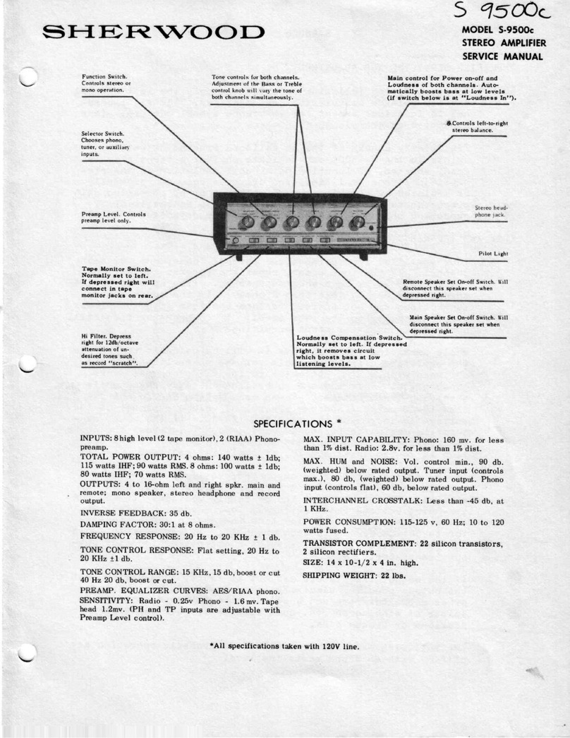
5-9400 AMPLIFITR
SERVICING
AND
ADJUSTMENT
To simplify the following descriptions only the left channel
and its related circuitries are described. The right channel
is identicaL except for reference symbol numbers
o (
See sche-
matic diagram
) nff reference numbers refer to Figure I unLess
otherwise specified. .
PreLiminary checks of the DC voltages present at various
points in your amplifier can indicate whether a transistor is
oPen, shorted r or otherwise malfunctioning. Fault isol-ation
in the preampfifier, tone amplifier, and driver stages ean
generaffy be isolated by checking the DC voltages. Many times
the circuit defect can be isolated by comparing gain measure-
ments at lKHz as indicated on the schematic or by comparing
the operating channel with the defective channe.l-.
AMPLIFIER
TLECTRONIC
RELAY
PROTECTION
AND
SPEAKER5YSTEM
CHEIK5:
This amplifier incorporates a special eLectronic over.load pro-
tection circuit which automatically disconnects the speakers
when danger to the power amplifier exists or when danger to
the speaker system exists. If there is no output to the speakers,
check the speaker connections for shorted wires or shorted
speakers. (
Sp"aker line resistances should not indicate less
than 4 ohm resistance on an ohmmeter.
)
The Electronic Re1ay Protection circuit consists of an eJ.ectronic
switch which senses two eonditions, output current and DC center
point voLtage, to protect both the power ampl-if
ier and the
speakets. This circuit limits the current delivered to the
speaker load and also protects the speaker from DC vol-tages in
the event of an amplifier device failure. A center point DC
shift is detected by dif f
erential- ampl-ifier TR702 and TR703, which
disconnects the power amplifier from the speaker J-oad
by way of
transistors TR704, TR705 and TR705, which deactivates a re1ay,
disccnnecting the speaker load. The power amplifier current
protection is obtained by transistors T
R701a and T
R701b with
associated components, which sense the current through the output
transistor resistors R524 and R525. Vrlhen
the peak currents
reach approximately 5 Amps, TR70l-aand TR701b
conduct, causing
mul-tivibrator action in conjunction with TR704, TR705, and TR705
to deactivate the relay at a recurring rate, thereby protecting
the amplifier from abnormal-
load conditions. This circuit will
continuely sample and disconnect the spearkel line untiL the ovex-
load condition is removed.
While servicing the ampl-ifier it will be valuable to operate the
amplif ier using a variabl-e vo.l-tage
power Iine (
VARI
AC
) equipped
with a line wattmeter to identify abnormal power consumption.
I nerease the power line voltage upward while observing the
wattmeter. Power consumption should not exceed 10-2U watts
(
loudness control volume at minimum
) .s the voltage is increased
Page 3
