SPECIFICATIONS
Description
Unit
Normal
Limit
Equalizer
range
(7
bands
x
2)
at
60
Hz,
150
Hz,
400
Hz,
1
kHz,
2.4
kHz,
6
kHz,
15
KHz
dB
8
842
Center
frequency
(Fo)
%
Fo
Fo+2
Total
harmonic
distortion
:
at
1
kHz,
all
controls
flat,
output
1
V.
%
0.01
0.02
at
1
kHz,
all
controls
max,
input
200
mV.
%
0.07
0.09
at
1
kHz,
all
controls
flat,
output
2
V.
%
0.005
0.01
|
_at
1
kHz,
all
controls
min.,
output
0.2
V
%
0.07
|
0.1
insertion
loss,
controls
flat
dB
-0.5
-0.5+2
Maximum
output
voltage
at
1
kHz,
THD
0.5%,
R/L
47
kohm
Vv
>6
>5
Frequency
responce
at
-3
dB
Hz
20
—
80000
40
-
50000
Signal
to
noise
ratio
(IHF
“A”
WTD/UNWEIGHTED)
dB
>95/90
>90/85
General
POWer
COMSUMPTIONS
<-+-eeeeseeesteseeeseeeetee
test
eet
tetaeetaetaeteseeeeeeneees
ee
eeeee
seer
eee
e
esas
teen
tee
gene
eee
ees
19W
Dimensions
(W
xHx
D)
ne
re
re
re
rer
ee
rn
oe
rrr
Power
requirements
:
A:
120
V
60
Hz
for
American/Canadian
version
B
:
120/220
V
60/50
Hz
multy
voltage
version
(switchable)
D
:
230
V
50
Hz
German/Gerneral
European
version
E
:
240
V
50
Hz
for
UK/Australian
version
G
:
220
V
50
Hz
for
Other
Area
Notes
:
440
x
80
x
245
mm
(17.3
3.19.6
inch)
Weight
(Net)
<--:ssssressssssesesseerseeseseneeaeneesessesesecessesersssnassenesnsesacnecnsnrcaesesansnenaseenesgsgts
3.1
kg
(6.8
Ibs)
1.
Nominal
specs
represent
the
design
specs.
All
units
should
be
able
to
apprcximate
these
some
will
exceed
and
some
may
drop
slightly
below
these
specs.
Limit
specs
represent
the
absolute
worst
condition
that
still
might
be
considered
acceptable
:
in
no
case
should
a
unit
fail
to
meet
limit
specs.
2.
This
manual
is
based
on
the
European
(D)
standard,
and
provides
information
on
regional
circuit
modification
throught
the
use
of
altemate
schematic
diagram
or
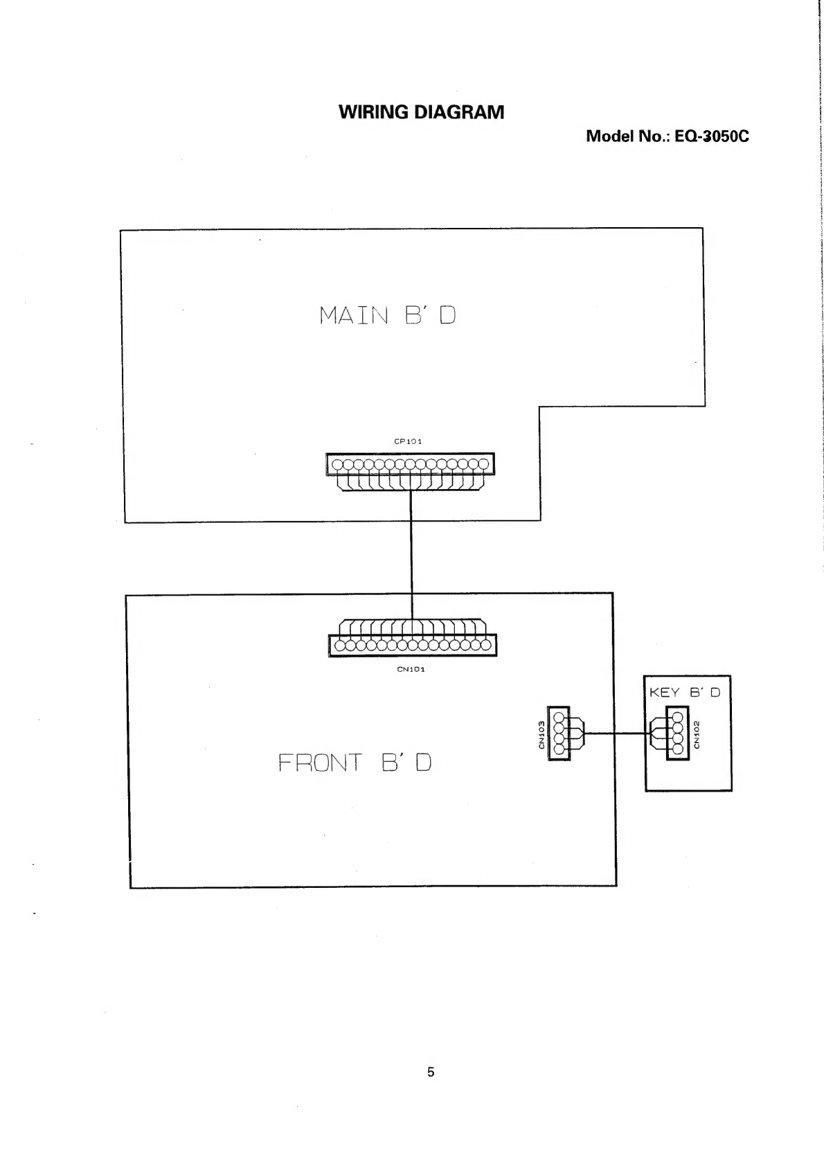
wiring
diagram,
and
information
on
regional
component
variations
therought
the
use
of
poarts
lists.
Design
and
specifications
subject
to
change
without
notice.
escunnstan
oniens
arsine
saersaenaiese
thie
mato