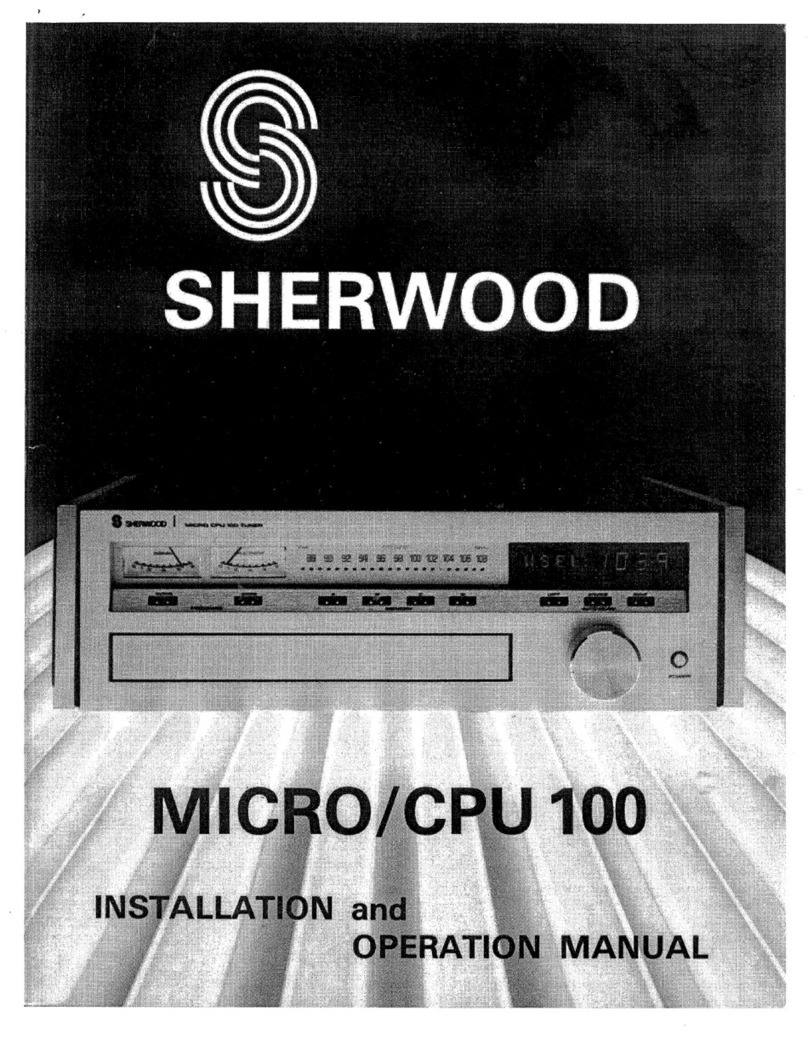
Sherwood TD120 User manual

1D120/1208
INSTALLATION
and
OPERATION
MANUAL

RISK
OF
ELECTRIC
SHOCK
00
MOT
OPEN
CAUTION:
TO
REDUCE
THF
RISK
OF
ELECTRIC
SHOCK,
DO
NOT
REMOVt
COVER
(OR
BACK}
NO
USER~SERVICEABLE
PARTS
INSIDE
REFER
SERVICING
TO
QUALIFIED
SERVICE
PERSONNEL
The
lightning
flash
with
arrowhead
symbol,
within
and
equi-
lateral
triangle,
is
intended
to
alert
the
user
to
the
presence
of
uninsulated
“‘dangerous
voltage”
within
the
product’s
enclo-
sure
that
many
be
of
sufficient
magnitude
to
constitute
a
risk
of
elevtric
shock
to
persons.
The
exclamation
point
within
an
equilateral
triangle
is
in-
tended
to
alert
the
user
to
the
presence
of
important
operating
and
maintenance
(servicing)
instructions
in
the
literature
ac-
companying
the
appliance.
SAFETY
INSTRUCTIONS
.
READ
INSTRUCTIONS
—
All
the
safety
and
operating
instructions
should
be
read
before
the
appliance
is
operated.
.
RETAIN
INSTRUCTIONS
—
The
safety
and
operating
instructions
should
be
retained
for
future
reference.
.
HEED
WARNINGS
—
Ail
warnings
on
the
appliance
and
in
the
operating
instructions
should
be
adhered
to.
.
FOLLOW
INSTRUCTIONS
—
All
operating
and
use
instructions
should
be
followed.
.
WATER
AND
MOISTURE
—
The
appliance
“should
not
be
used
near
water
—
for
example
near
a
bathtub,
washbowl,
kitchen
sink,
laundry
tub,
in
a
wet
basement,
or
near
a
swimming
pool,
etc.
.
VENTILATION
—
The
appliance
should
be
situated
so
that
its
location
or
position
do
not
interfere
with
its
proper
ventilation.
For
example,
the
appliance
should
not
be
situated
on
a
bed,
sofa,
rug,
or
similar
surface
that
may
block
the
ventilation
openings;
or,
placed
in
a
built-in
installation
such
as
a
bookcase
or
cabinet
that
may
impede
the
flow
of
air
through
the
ventilation
openings.
.
HEAT
—
The
appliance
should
be
situated
away
from
heat
sources
such
as
radiators,
heat
reg-
isters,
stoves,
or
other
appliances
(including
amplifiers)
that
produce
heat.
.
POWER
SOURCES
—
The
appliance
should
be
connected
to
a
power
supply
only
of
the
type
described
in
the
operating
instructions
or
as
marked
on
the
appliance.
.
POWER-CORD
PROTECTION
—
Power-supply
cords
should
be
routed
so
that
they
are
not
likely
to
be
walked
on
or
pinched
by
items
10.
11.
12.
placed
upon
or
against
them,
paying
particular
attention
to
cords
at
plugs,
convenience
recep-
tacles,
and
the
point
where
they
exit
from
the
appliance.
CLEANING
—
The
appliance
should
be
cleaned
only
as
recommended
by
the
manufacturer.
POWER
LINES
—
An
outdoor
antenna
should
be
located
away
from
power
lines.
OUTDOOR
ANTENNA
GROUNDING
-—
If
an
outside
antenna
is
connected
to
the
appliance,
be
sure
the
antenna
system
is
grounded
so
as
to
provide
some
protection
against
voltage
surges
and
built
up
static
charges.
Section
810
of
the
National
Electrical
Code,
ANSI/NFPA
No.
70-
1978,
provides
information
with
respect
to
proper
grounding
of
the
mast
and
supporting
structure,
grounding
of
the
lead-in
wire
to
an
antenna
discharge
unit,
size
of
grounding
con-
ductors,
location
of
antenna-discharge
unit,
connection
to
grounding
electrodes,
and
re-
quirements
for
the
grounding
electrode.
The
Example
shown
here
is
for
an
FM/TV
an-
tenna
installation.
However,
the
basic
grounding
circuit
and
conductor
size
well
also
apply
to
external
AM
antenna
installations.

EXAMPLE
OF
ANTENNA
GROUNDING
AS
PER
NATIONAL
ELECTRICAL
CODE
INSTRUCTIONS
13.
14.
15.
GROUND
CLAMP
DOWNLEAD
OR
ANTENNA
LEAD-IN
WIRE
DISCHARGE
MAST
UNIT
GROUND
TO
WIRE
RECEIVER
GROUND
WIRE
GROUND
CLAMPS
SUITABLE
GROUNDING
ELECTRODE
DRIVEN
8’
INTO
THE
EARTH
(2.44
METERS)
a.
Use
No.
10
AWG
copper
or
No.
8
AWG
aluminum
or
No.
17
AWG
copper-clad
steel
or
bronze
wire,
or
larger
as
ground
wires
for
both
mast
and
lead-in.
b.
Secure
lead-in
wire
from
antenna
to
antenna
discharge
unit
and
mast
ground
wire
to
house
with
stand-off
insulators,
spaced
from
4
feet
(1.22
meters)
to
6
feet
(1.83
meters)
apart.
c.
Mount
antenna
discharge
unit
as
closely
as
possible
to
where
lead-in
enters
house.
NONUSE
PERIODS
—
The
power
cord
of
the
appliance
should
be
unplugged
from
the
outlet
when
left
unused
for
a
long
period
of
time.
OBJECT
AND
LIQUID
ENTRY
—
Care
should
be
taken
so
that
objects
do
no
fall
and
liquids
are
not
spilled
into
the
enclosure
through
openings.
DAMAGE
REQUIRING
SERVICE
—
The
ap-
pliance
should
be
serviced
by
qualified
service
personnel
when:
A.
The
power-supply
cord
or
the
plug
has
been
damaged;
or
B.
Objects
have
fallen,
or
liquid
has
been
spilled
into
the
appliance;
or
16.
C.
The
appliance
has
been
exposed
to
rain;
or
D.
The
appliance
does
not
appear
to
operate
normally
or
exhibits
a
marked
change
in
performance;
or
E.
The
appliance
has
been
dropped,
or
the
enclosure
damaged.
SERVICING
—
The
user
should
not
attempt
to
service
the
appliance
beyond
that
described
in
the
operating
instructions.
All
other
servicing
should
be
referred
to
a
qualified
service
per-
sonnel.

Unpacking
and
Installation—
Congratulations
on
Your
Purchase!
Your
new
high
fidelity
Tuner
is
designed
to
deliver
maximum
enjoyment
and
years
of
trouble
free
service.
Please
take
a
few
moments
to
read
this
manual
thoroughly.
It
will
explain
the
features
and
operation
of
your
Tuner
and
help
insure
a
trouble
free
installation.
Please
unpack
your
Tuner
carefully.
We
recommend
that
you
save
the
carton
and
packing
material.
They
will
be
helpful
should
you
ever
need
to
move
your
unit
and
may
be
required
if
you
ever
need
to
return
it
for
service.
Your
Tuner
is
designed
to
be
placed
in
a
horizontal
position
and
it
is
important
to
allow
at
least
two
inches
of
space
behind
your
unit
for
adequate
ventilation
and
cabling
convenience.
To
avoid
early
damage,
never
place
the
unit
near
radiators,
in
front
of
heating
vents,
in
direct
sun
light,
or
in
excessively
humid
or
dusty
location.
Connect
your
complementary
components
as
illustrated
in
the
following
section.
Rear
Panel
Connections
TO
OUTDOOR
FM
ANTENNA
FOR
DISTANT
RECEPTION
24
\NDOOR
DIPOLE
FOR
LOCAL
RECEPTION
EXTERNAL
ANTENNA
FOR
WEAK
SIGNALS
AM
ANTENNA
ROD
ROTATE
AWAY
FROM
CHASSIS
FOR
BEST
RECEPTION
OF
AM
STATION
WARNING:
TO
PREVENT
FIRE
OR
SHOCK
HAZARD,
DO
NOT
EXPOSE
THIS
APPLIANCE
TO
RAIN
OR
MOISTURE.

1.
AM
FERRITE
BAR
ANTENNA
This
Tuner
comes
with
an
AM
built-in
bar
antenna.
Rotate
this
bar
antenna
away
from
chassis
for
best
reception
©
of
AM
stations.
,
2.
FM
ANTENNA
UNBALANCED
CONNECTION
This
connector
is
used
for
60
to
75
ohm
unbalanced
coaxial
cable
connection.
3.
FM
ANTENNA
BALANCED
TERMINAL
This
240
to
300
ohm
balanced
input
is
used
for
standard
TV
twin
lead
connection.
The
dipole
antenna
provided
with
your
Tuner
should
be
adequate
for
local
FM
reception.
Attach
the
antenna’s
arm
horizontally
to
a
non-
metallic
surface
such
as
a
window,
a
wall,
or
the
rear
surface
of
a
cabinet
or
shelf.
In
general,
the
antenna
is
best
positioned
when
it is
as
high
as
possible
above
floor
level
and
its
arms
are
perpendicular
to
the
source
of
trans-
mission.
If
you
are
located
a
considerable
distance
from
FM
transmitters
or
in
a
ferroconcrete
building,
an
out-
door
FM-antenna
may
be
required
to
reduce
background
noise,
fading
or
interference.
4.
AM
GROUND
TERMINAL
For
best
results
when
using
an
exteriiul
AM
antenna,
the
Tuner’s
chassis
should
be
properly
grounded
and
this
is
easily
done
by
connecting
this
terminal
to
the
nearest
water
pipe
or
metal
conduit
that
goes
to
true
ground.
5.
EXTERNAL
AM
ANTENNA
In
ferroconcrete
buildings
or
in
areas
remote
from
broadcast
stations,
the
built-in
antenna
may
not
prove
adequate.
To
supplement
the
built-in
antenna,
connect
10
to
20
feet
of
insulated,
flexible,
single
conductor
wire
to
this
terminal,
but
this
wire
should
be
kept
away
from
all
speaker
cables
and
power
cables
and
run
in
a
straight
line
along
a
nonmetallic
baseboard
or
under
a
rug.
6.
TUNER
OUTPUT
JACKS
These
output
jacks
are
for
the
connection
between
the
Tuner
and
your
matching
amplifier.
Connect
one
end
of
your
leads
to
these
output
jacks
and
plug
the
other
end
to
the
TUNER
inputs
on
your
amplifier.
7,
AC
INPUT
CORD
Plug
this
cord
into
AC
outlet.

Front
Panel
Controls
1.
POWER
SWITCH
&
ITS
INDICATOR
To
turn
the
power
ON
or
OFF,
depress
the
POWER
switch
in
or
out.
2.
FLUORESCENT
DISPLAY
This
fluorescent
display
indicates
the
station
frequency
for
FM
in
MHz
and
AM
in
KHz.
3.
FM/AM
BAND
SELECTOR
Push
switch
for
selecting
desired
band;
FM
or
AM.
4.
MEMORY
BUTTON
This
button
is
used
for
entering
the
frequencies
of
FM
and
AM
stations
into
each
of
6
station
memories
(5).
When
you
touch
this
button,
MEMORY
INDICATOR
in
the
fluorescent
display
will
light
for
8seconds
and
it
allows
you
to
enter
the
FM
or
AM
station
just
displayed
on
the
FREQUENCY
DISPLAY
(2)
into
any
number
of
the
STATION
ADDRESSES
(5)
during
this
interval.
For
example,
if
you
want
to
memorize
the
just
dis-
played
100.10
MHz
of
FM
station
into
STATION
ADDRESS
NO.
2,
touch
MEMORY
button
(4)
first,
(then
MEMORY
INDICATOR
will
light)
and
touch
the
STATION
ADDRESS
NO.
2
button
in
sequence,
the
ME-
MORY
INDICATOR
will
come
off
immediately
and
the
ADDRESS
NO.
2
INDICATOR
will
come
on,
indicat-
ing
that
100.10
MHz
has
been
memorized
into
ADDRESS
NO.
2.
In
AM,
the
procedure
is
the
same
as
the
FM
case
except
changing
band
to
AM
by
pushing
AM
button
(3).
5.
STATION
ADDRESS
NO.
BUTTONS
&
THEIR
INDICATORS
This
tuner
enables
you
to
memorize
each
of
6
stations
for
both
FM
and
AM
bands,
totally
12
stations.
These
soft
touch
buttons
are
used
for
the
MEMORY
and
RECALL
of
the
FM
and
AM
stations,
and
the
relative
in-
dicators
indicate
that
a
station
has
been
memorized
or
recalled.
See
OPERATION
page
for
more
details.
5

6.
MONO/MUTE
OFF
SWITCH
This
switch
in
pushed-out
position
will
allow
you
to
listen
STEREO
signal
in
FM
mode
and
simultaneously
suppress
interstation
hiss
(MUTING-ON
state).
In
this
mode,
the
weak
stereo
FM
reception
will
be
switched
to
MONO
mode
automatically;
if
you
wish
to
receive
such
stations
in
stereo,
check
the
direction
of
FM
antenna
or
an
outdoor
antenna
may
be
required.
In
this
mode,
the
desired
weak
or
distant
FM
stations
may
be
muted
along
with
the
hiss
noise,
too;
if
you
wish
to
pick
up
such
stations,
push
this
switch
(6)
in
to
permit
reception
of
the
weak
stations
in
the
less
noisy
MONO
mode
and
tune
a
desired
station
in
MANUAL
mode
(7).
7.
AUTO/MAN
SWITCH
Switch
for
selecting
the
desired
scanning
mode
with
UP/DOWN
(8)
tuning
button;
AUTO
or
MANUAL
scanning
as
indicated
on
the
front
panel.
In
AUTO
operation,
scanning
is
automatically
continued
up
or
downward
until
the
next
station
is
picked
up
with
touching
UP/DOWN
tuning
button
(8).
In
MANUAL
operation,
the
frequency
display
(2)
is
skipped
by
one
channel
up
or
downward
from
the
just
displayed
frequency
whenever
UP
or
DOWN
button
is
touched.
If
you
keep
depressing
the
UP/DOWN
tuning
button,
skipping
will
automatically
continue
after
a
while
until
the
UP/DOWN
tuning
button
is
released,
or
until
the
ends
of
band
frequency
are
reached.
NOTE:
REMEMBER
THAT
BOTH
THE
INTERVAL
OF
AUTO
SCANNING
AND
SKIPPING
IN
MANUAL
TUNNING
IS;
BAND
USA
version
Europe
version
FM
0.1
MHz
0.05
MHz
AM
10
KHz
9
KHz
8.
UP/DOWN
TUNING
BUTTON
To
scan
the
tuning
frequency
up
or
downward
from
the
just
displayed
frequency
(2),
touch
the
UP
or
DOWN
button.
FM/AM
band
selector
(3)
and
AUTO/MAN
switch
(7)
are
related
with
the
UP/DOWN
tuning
mode.
9.
FM
STEREO
INDICATOR
Automatically
lights
up
when
FM
station
broadcasts
in
STEREO.
On
weak
or
distant
STEREO
station,
the
TUNER
is
automatically
switched
into
a
MONO
mode
to
reduce
noise.
10.
SIGNAL
STRENGTH
INDICATORS
Indicates
relative
signal
strength
of
AM
or
FM
stations.
Useful
in
the
orientation
of
antennas.
Operations
LISTENING
FM
BY
AUTO
SCANNING
.
Push
POWER
switch
(1)
in
to
turn
on
the
power.
.
Push
FM
band
selector
(3).
.
Set
MONO/MUTE
OFF
switch
(6)
to
STEREO;
pushed-out
position.
.
Set
AUTO/MAN
(7)
switch
to
AUTO;
pushed-out
position.
.
Touch
UP
or
DOWN
tuning
button
(8),
then
Auto
scanning
will
stop
at
the
next
station.
.
Repeat
touching
UP
or
DOWN
tuning
button
(8)
until
you
get
the
broadcasting
station
you
want.
NOR
WN
LISTENING
WEAK
FM
STATION
1.
Push
FM
band
selector
(3).

2.
Set
MONO/MUTE
OFF
switch
(6)
to
MONO;
pushed-in
position.
3.
Set
AUTO/MAN
switch
(7)
to
MANUAL;
pushed-in
powition,
then
FM
muting
will
be
released
to
permit
reception
of
the
weak
stations
as
the
less
noisy
MONO
mode.
4.
Keep
depressing
UP
or
DOWN
tuning
button
(8)
until
a
desired
weak
station
is
picked
up.
NOTE:
If
a
weak
desired
station
is
skipped
in
AUTO
scaning,
we
recommend
you
try
to
improve
the
antenna
first
(check
the
position
and/or
direction
of
your
indoor
dipole
antenna
or
an
outdoor
antenna
may
be
required).
See
item
3
of
REAR
PANEL
CONNECTIONS.
LISTENING
AM
STATION
1.
Push
AM
band
selector
(3).
2.
Set
AUTO/MAN
switch
to
AUTO;
pushed-out
position.
3..
Touch
UP
or
DOWN
tuning
button
(8),
then
AUTO
scaning
will
stop
at
the
next
station.
4.
Repeat
touching
UP
or
DOWN
tuning
button
until
a
desired
station
is
picked
up.
5.
For
weak
signal
reception,
set
AUTO/MAN
switch
to
MUNUAL
and
repeat
touching
UP
or
DOWN
tuning
button.
HOW
TO
MEMORIZE
(PRESET)
&
RECALL
A
STATION
1.
Remember
that
this
tuner
enables
you
to
memorize
totally
12
stations;
6
stations
for
FM
and
another
6
stations
for
AM.
2.
To
memorize
the
desired
FM
stations,
select
maximum
6
frequencies
from
your
desired
stations,
tune
one
by
one
either
by
AUTO
or
MANUAL
tuning,
touch
MEMORY
button
(4)
and
STATION
ADDRESS
NO.
1
(5)
in
sequence
for
the
first
selected
FM
station.
Repeat
touching
MEMORY
button
and
STATION
ADDRESS
NO.
buttons
in
sequence
as
your
next
selected
station
is
tuned.
3.
To
memorize
the
desired
AM
stations,
the
procedures
are
the
same
as
those
of
above
FM
case
except
change
band
to
AM
by
touching
AM
button
(3).
.
4.
To
recall
the
memorized
stations,
select
the
desired
band
(FM
or
AM)
and
then
touch
only
the
STATION
ADDRESS
NO.
button
to
which
you
want
to
listen,
then
the
memorized
frequency
will
be
displayed
on
the
FREQUENCY
DISPLAY
(2)
immediately.
Circuit
Description
@
Quartz
PLL
synthesized
tuning
system
with
full
dynamic
fluorescent
display.
@
Dual
gate
MOS-FET
RF
amplifier
+3
section
varactor
diode
front
end,
2
pair
matched
linear
phase
IF
ceramic
filters,
double
tuned
quadrature
detector,
PLL
MPX
demodulator
with
19
KHz/38
KHz
filters
for
FM
cir-
cuitry.
@
2
section
varactor
diode
and
wide
band
ceramic
filter
for
AM
circuitry.
@
Outstanding
switching
muting
circuitry.

Specifications
FM
SECTION
Tuning
Range
Scanning
Frequency
interval
(AUTO/MANUAL)
Usable
Sensitivity
IHF
at
S+N+D/N+D
=
30
dB
THD
at
1
KHz,
100%
MOD,
Mono
Stereo
‘Stereo
Separation
at
1
KHz
Signal
to
Noise
Ratio
IHF
Mono
Stereo
Frequency
Response
20
Hz-15
KHz
Audio
Output
Voltage,
1
KHz,
100%
Mod
De-emphasis
AM
SECTION
Tuning
Range
‘Scanning
Frequency
interval
(AUTO/MANUAL)
Usable
Sensitivity
IHF
at
S+N/N
=
20
dB,
Bar
antenna
Signal
to
noise
Ratio,
30%
Mod
ref.
Audio
Output
Voltage,
400
Hz,
30%
Mod
Power
Consumption
Unit
Dimensions
(W
x
H
x
D)
Unit
Weight
USA
Version:
87.5-108.00
MHz
Europe
Version:
87.50-108.00
MHz
USA
Version:
0.1
MHz
Europe
Version:
0.05
MHz
2.0uV
(11.2
dBf)
0.12%
0.15%
50dB
75
dB
70
dB
+0.5/—1
dB
600mV
USA
Version:
75
Sec
Europe
Version:
S5Ou
Sec
USA
Version:
520-1710
KHz
Europe
Version:
522-1611
KHz
USA
Version:
10
KHz
Europe
Version:
9
KHz
300uV/m
45
dB
150mV
11
Watts
440
x
70
x
200
mm
4.7
Kg/10
Lbs.
6
ozs.
NOTE:
Design
and
specifications
subject
to
change
without
notice
for
improvements.

9007010410
This manual suits for next models
1
Table of contents
Other Sherwood Tuner manuals