Shift Power MAGNUM User manual
Reading time: 8min
Installation manual Race Unit MAGNUM
Part № RM-Y6
Please read carefully before attempting any use of this product!
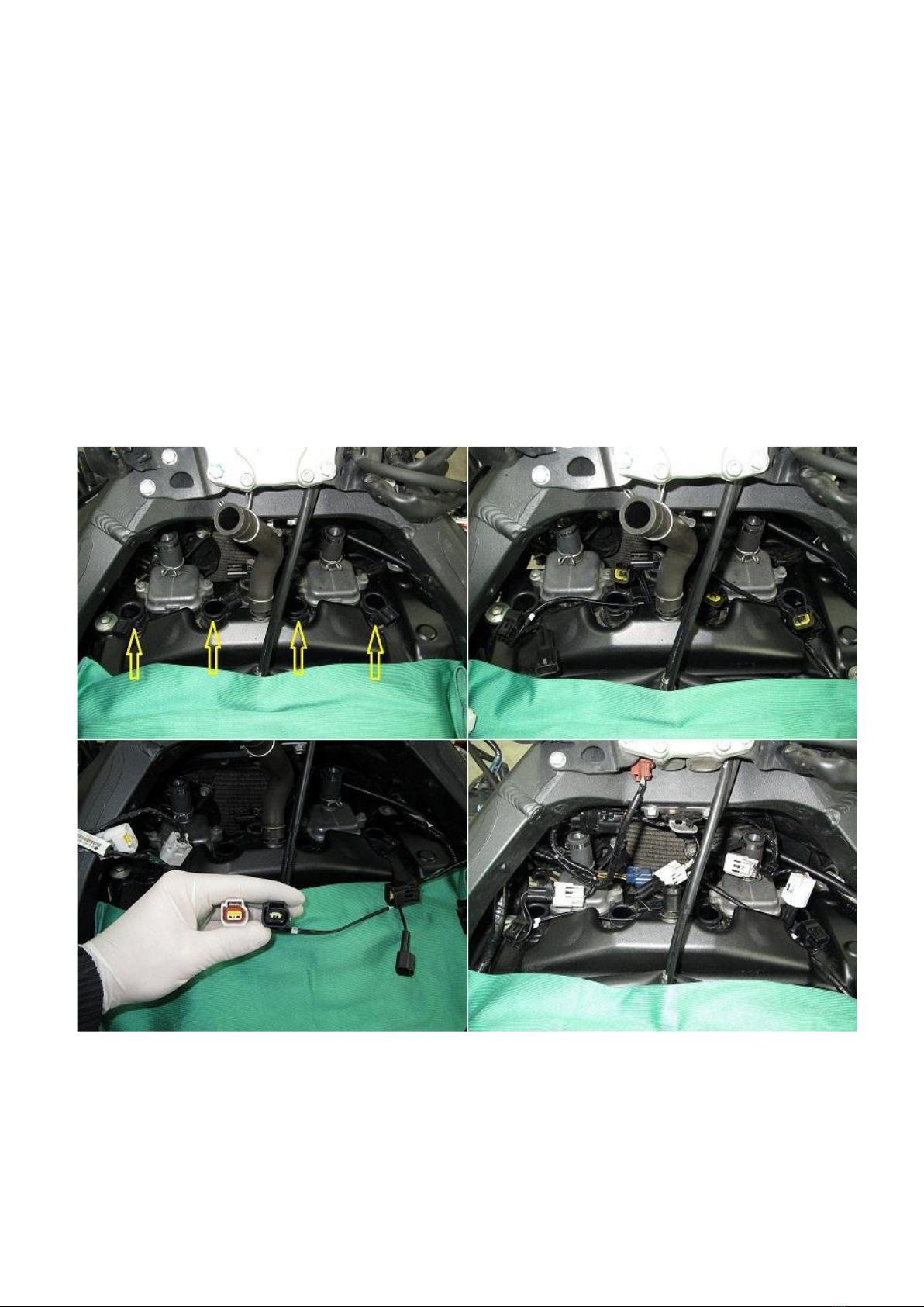
To install Race Unit MAGNUM you have to:
1. Gain access to the ignition coils (for best results refer to your motorcycle service
manual). Plug in the control box female connectors to the ignition coils and the male
connectors to the bike's harness. You must connect each male and female connector pair to
the same corresponding cylinder no matter left to right or right to left!
Stick type coils view
IMPORTANT NOTE: Make sure when plugging the connectors that you press them well
enough to lock, this will provide sealed and reliable electrical connection, important for the
function of the system. Find appropriate place for the control box and route the cables, they
are high quality, automotive class cables however you must: Avoid moving parts as they
might damage them, the best way is to follow other cables from the bike's harnes, use cable
ties to fasten them. Make sure the place for the control box is away from heavy vibrations,
heat, and it is not constantly exposed to rain and water.

NOTE: Race Unit Magnum must connect direcly to the ignition coils, if you use another
product(s) for altering or modifying the ignition coil signals (that needs to be connected to
the ignition coils as well) please contact us to confirm if they can work along each other!
The control box requires negative (ground) connection to power up, connect the control box
single black wire with ring terminal to the battery NEGATIVE (-) lead ! NOTE: You must never
run or even crank the engine when the control box is connected to the ignition coils
without the single black wire connected to the battery negative lead! Do not use bolts from
the chassis or engine to connect the control box single black wire!
2. Connect the control box pink wire with Posi-Tap connector to the rear wheel rotation
sensor signal (Black color wire)
Posi-Tap connector installation guide:
1. Do not strip run wire.
2. Unscrew the big end cap counter-clockwise
3. Insert the run wire in the big end cap slot.
4. Screw the big end cap to pierce and provide signal.
Speed sensor signal check: With everything connected and rear wheel lifted on a paddock stand,
turn the ignition key on, the engine kill switch must be in RUN position, the gearbox in neutral, the
engine must NOT be running. Rotate the rear wheel by hand at this point the first digit of the
display must flicker with every pulse from the vehicle speed signal, if not recheck your speed sensor
connection and repeat the testing procedure.
3. Remove the existing tie rod and install the shift sensor with the fitting rod(s) provided to
its place. Route the wire to the control box and plug it in. When installing the sensor, make
sure all counter nuts are locked and the sensor wire is not under tension when pressing the
gear lever all the way up and down. The rod and sensor internal threads are made with DUAL
THREADS (left and right hand at the same time) which makes fitting universal.
NOTE: Fasten the sensor cable using cable tie to the sensor body or tie rod to prevent it
vibrating when bike is in motion, not doing so may result in long term damage to the cable
core and shift sensor failure!
NOTE: Use the slotted end in top side and a 10mm open end wrench (spanner) to hold the
sensor body when tightening counter locking nuts.

NOTE: The gearbox pivot arm must extend to 90 degrees with the shift rod in order to
receive equal force in both directions, if not set correctly the gearbox may not react
accordingly and miss gears when using the quickshifter!
After this is done, turn the ignition key ON, make sure the engine kill switch is in RUN
position and the gearbox is in neutral, at this time the control box must power up and enter
normal operation displaying SP flashing.

BEFORE USING THE QUICKSHIFTER YOU MUST ENSURE THE CORRECT SENSOR MOTION FOR
YOUR SHIFT SETUP IS SELECTED, PLEASE REFER TO THE FOLLOWING TABLE - OPTION SS
- To enter setting mode: Press and hold LB and RB together then power up the control box
by turning the ignition key on, engine kill switch must be in RUN position and gear in neutral.
Hold down the buttons for 3 seconds until the countdown timer elapses.
- To cycle through the main parameters press LB
- To enter a particular parameter press RB
- To exit one level up in the menu press and hold LB for 3 seconds.
- To exit the setting mode power down the control.
The following is a menu table for adjusting the control box parameters
Parametar
Description
Value
St
Adjust the engine
interrupt time for
shifting gears
UP(1-2-3-4-5-6)
45ms - 95ms
(5ms increments)
(60ms –default value)
SS
Controls the shift sensor
motion for shifting gears
UP(1-2-3-4-5-6)
PH = PUSH
PL = PULL
(PH –default value)
Ad
Sets the Launch Control
and Pit Limiter RPM
limits
When LC displays engage on
1st gear accelerate the
engine to the desired RPM
and press RB once to set the
limit
LC flashes 5 times to
indicate settings are
accepted
When PL displays engage
on 1st gear accelerate the
engine to the desired
speed and press RB once
to set the limit
PL flashes 5 times to
indicate settings are
accepted
dG
q - 0/1/2/3
This parameter controls
the quickshifter magnum
level by allowing
controlled cylinder
volumes to be ignited in
the exhaust
q0
Deactivated
q1
4 cylinder
volumes are
ignited in
the exhaust
q2
8 cylinder
volumes are
ignited in the
exhaust
(default after
reset)
q3
12 cylinder
volumes are
ignited in the
exhaust
dG
L
Controls the launch
control magnum feature
L0
Deactivated
(default value)
L1
Activated
US
Controls the ultra-
smooth shift feature
U0
Deactivated
U1
Activated
(default value)
SC
Shift sensor sensitivity
control - adjustable in 5
RPM ranges and 3 levels
of sensitivity
1 = 3000 - 5000 RPM
2 = 5000 - 7000 RPM
3 = 7000 - 9000 RPM
4 = 9000 - 11000 RPM
5 = above 11000RPM
A = low
b = medium
C = high
default values
(1A, 2b, 3c, 4c, 5c)

The following is shift sensor calibration procedure. Perform only if you are replacing a new
shift sensor or you have reset the control box to factory settings.
1. Unplug the shift sensor from the Full Race control box.
2. Power up the Full Race control box by turning the ignition key on and engine kill
switch in RUN position.
3. Plug in the shift sensor to the Full Race control box.
4. Ph displays now compress the shift sensor all the way until solid at once without
backing off! Release the shift sensor to normal position and the control box displays a
number from 48 to 53 is normal operating value if different repeat the procedure
from the beginning.
5. Pl displays now extent the shift sensor all the way until solid at once without backing
off! Release the shift sensor in normal position and the control box displays a number
from 14 to 18 is normal operating value if different repeat the procedure from the
beginning.
NOTE the above values are correct for DMU sensor if the sensor you’re calibrating
has no part number means its DMS and operating values are PH(55-59)/PL(34-38)
Activating the Launch Control:
Before operating the launch control you have to set the RPM limit from the setting menu
parameter Ad! When new or after reset the launch control is deactivated!
How to activate:
- The vehicle speed must be 0km (rear wheel standing still).
- The engine RPM must drop at idle for at least 1,5seconds.
- The engine RPM must raise to the pre-set Launch Control RPM limit (twist the throttle
here).
What is MAGNUM Launch Control
This feature ignites the fuel mixture which is normally expelled when the launch control
holds the RPM to the set limit.
!WARNING!
- NEVER USE THIS FEATURE WITH FACTORY FITTED EXHAUST SYSTEMS OR ONES
CONTAINING CATALITYC CONVERTERS!
- DO NOT USE THIS FEATURE IF YOUR EXHAUST SYSTEM IS NOT WELL MADE AND SEALED
FROM LEAKING EXHAUST FUMES!
- DO NOT TWIST THE THROTTLE PAST 50% !
- DO NOT HOLD THE ENGINE IN LAUNCH CONTROL WITHOUT ACTUALLY LAUNCHING FOR
MORE THAN 3 SECONDS AS THE EXHAUST BECOMES RED HOT AND NO AIR FLOW TO COOL
IT DOWN!
What is Quickshifter MAGNUM
This option is unique to MAGNUM control box and is capable of controlling the ignition
timing which results in extremely fast and in the same time smooth shifts on the other hand
it gives you a nice pop and flame spit on every shift. NOTE: MAGNUM feature levels 2 and 3
are recommended for use on straight pipe exhaust systems only! The OEM exhaust will
become very hot when arresting the flames.
Quickshifter MAGNUM is controlled by the parameter dG/(q-0-1-2-3)
- q0 Deactivates magnum feature
- q1 Magnum feature is active level 1
- q2 Magnum feature is active level 2

- q3 Magnum feature is active level 3
What is Pit Limiter mode
Before operating the pit limiter mode you have to set the RPM limit, parameter Ad/PL see
table above. Pit limiter mode when activated restricts the engine speed to a user pre-set
value and is controlled via handlebar switch provided in the kit.
What is the (Ultra Smooth) shift feature:
This option will restore the power on the next gear when using the quickshifter by firing
sequential cylinders allowing smooth transition between gears, particularly suitable for
cruise and city riding.
What is the (SC) shift sensor sensitivity control:
This option allows you to adjust the force required by the shift sensor to initiate a shift
depending on engine RPM. You can adjust 3 levels of force (A = Low, b = Med, c = High)
depending on 5 RPM ranges respectively: 1 = (3k to 5k); 2 = (5k to 7k); 3 = (7k to 9k); 4 = (9k
to 11k); 5 = (11k to red line). This option has been pre-set from factory we recommend to
test ride before changing the parameters.
Force reset of the control box
With everything connected turn the ignition key on with the engine kill switch in RUN
position, the engine must not be running then press and hold the shift lever in the direction
of upshifting all the way in –at this point the control box will display a timer hold the shift
lever until “rt” starts flashing. Module is now reset to the factory pre-set values.
Tips on adjusting your Quickshifter!
The MAGNUM Quickshifter arrives with best overall setting to your motorcycle make and
model. We strongly recommend you to test ride it before changing the St settings. Use the
following as a general guide when adjusting your Quickshifter:
If when using the Quickshifter the gearbox seems to push back the shift lever, the shift feels
rough and you have experienced missed gears - this means that the gearbox needs more
time to react –increase the St shift time.
If when using the Quickshfiter the motorcycle front dives for too long and the shift seems
slow - this means that you have to lower the shift time –decrease the St shift time. Best
results for most motorcycles are achieved with the following time settings - (60ms-70ms).
The Quickshifter has a threshold RPM which means that the engine speed must exceed the
minimum threshold in order to activate the Quickshifter function. The factory setting are
over 3000RPM and this is not adjustable.
If for some reason you're experiencing difficulties adjusting your Shift Power product, you
think it is not functioning as expected or you would like to share your opinion please feel free
to contact us to support you with a professional help.
Web: https://www.shiftpower.co.uk Email: info@ShiftPower.co.uk
This product is covered by one year warranty against malfunctions from the original date of
purchase under the following conditions –link click here.
Warranty disclaimer:
Shift Power Ltd shall not under any circumstances, be liable for any special, incidental or
consequential damaged including, person, party or property, but not limited to, damage loss
of cost of purchased or replacement goods or service, claims of customers of the purchaser,

which may arise and/or result from sale or use of these parts. Installation of these parts
could adversely affect the engine manufacturer warranty coverage.
Thank you for choosing the Race Unit MAGNUM system
enjoy!
This manual suits for next models
1
Other Shift Power Motorcycle Accessories manuals


