Shimaden SD17 Series User manual

MSD17-E01-B
Jun. 2022
1
Digital Indicator
SD17 Series
Instruction Manual
Detailed Version
Please ensure that this instruction manual is given to the final user of the instrument.
Preface
Thank you for purchasing Shimaden products. Please check that the delivered product is the correct item that you ordered. This instruction manual is meant for
those who will be involved in the wiring, installation, operation and routine maintenance of the SD17 series, and describes about cautions, mounting, wiring,
functions, and operation. Please observe the contents, and always keep the manual close at hand when handling this instrument.
The following headings give a description of matters requiring user attention concerning safety, damage to machines and equipment, additional explanations and
commentaries are described under the following headings.
WARNING
Items concerning matters that may lead to an accident producing human injury or death, if the warning is not observed.
CAUTION
Items concerning matters that may lead to an accident producing damage to machines or equipment, if the caution is neglected.
Note
Note
Additional explanations and commentaries.
Safety cautions
WARNING
•The SD17 Series digital indicator are designed for industrial use to control temperature, humidity and other physical values. Do not apply this instrument to
other objects in a way that may cause grave effects on human safety.
•In using this product, be certain to house it, for example, in a control panel, so that the terminals cannot come into contact with personnel.
•Do not take this instrument out of its case or put your hand or any conductor inside the case. Such conduct may lead to an accident that endangers life or
causes serious injury due to electric shock.
CAUTION
•Toavoid damage to the connected equipment, facilities or the product itself due to a fault of the product, safety countermeasure must be taken before usage,
such as proper installation of the fuse and the overheating protection device.
•An alert symbol is printed on the terminal nameplate attached to the case. It warns not to touch the electrical charging parts when the power is being
supplied, so as to avoid the risk of electrical shock.
•Install a switch or breaker on the external source power circuit connecting to the source power terminal as a means to shut down the power.
The switch or breaker should be installed adjacent to the instrument in a position that allows the operator easy access.
•Regarding the fuse:
Since this instrument has no built-in fuse, make sure to install a fuse in the electric circuit connecting to the source power terminal.
Install the fuse in a position between the switch or breaker, and the instrument and attach it to the L side of the source power terminal.
Fuse Rating: 250V AC 1.0A/Time-lag (T) or Medium Time-lag (M)
•The load of voltage and current to be applied to the output terminal (analog output) and the alarm terminal must be within the rated range. If the range is
exceeded, the instrument will overheat causing the risk of the instrument being damaged and its life reduced.
As for the rating, please refer to "11. Specification."
The unit connected to the output terminal should conform to the requirements of IEC61010-1.
•Do not apply over-rated voltage or current to the input terminal. That will cause the risk of the instrument being damaged and its life reduced.
As for the rating, please refer to "11. Specification."
In case the input type is voltage (mV or V) or current (4 - 20mA), the unit connected to the output terminal should conform to the requirements of
IEC61010-1.
•Take care to prevent metal or other foreign matter from obstructing the ventilating hole for heat radiation. It will cause damage to the instrument and may
even result in fire.
•Do not block the ventilating hole. Also avoid dust accumulation. Any rise in temperature or insulation failure may result in a risk of the instrument being
damaged and its life reduced. As for the clearance space for installing the instrument, refer to "2-3 External dimensions and panel cutout."
•Repeating withstanding tests on voltage, noise, surging may lead to the deterioration of the instrument, so please be careful.
•Strictly refrain from remodeling and using the instrument improperly.
•It takes 30 minutes to display the correct temperature after applying power to the digital Indicator. (Therefore, turn the power on more than 30 minutes prior
to the operation.)
•To ensure safety and maintain the functions of this device, do not disassemble this device. If this device must be disassembled for replacement or repair,
contact your dealer.
•This device is designed for mounting on the panel. Only the device mounted on the front of the panel facing outward is of protection class of IP66. Do not
use for the device not facing outward or in environment where water or solids in excess of IEC60529 may get inside.
Copyright © SHIMADEN CO., LTD. All rights reserved.

SD17 Instruction Manual
2
Contents
1. Introduction························································································································· 3
1-1. Check before use·······························································································································3
1-2. Notes for use ····································································································································3
2. Installation and wiring············································································································ 3
2-1. Installation site (environmental conditions) ······························································································3
2-2. Mounting··········································································································································3
2-3. External dimensions and panel cutout ····································································································4
2-4. Wiring··············································································································································4
2-5. Terminal arrangement·························································································································4
3. Names and functions for front panel ························································································· 5
3-1. Names·············································································································································5
3-2. Functions ·········································································································································5
4. Measuring range code table···································································································· 5
5. Error messages···················································································································· 5
6. Instruction for each screen ····································································································· 6
6-1. Screen sequences ·····························································································································6
6-2. Power ON Screen Group·····················································································································7
6-3. Mode 0 Screen Group·························································································································7
6-4. Mode 1 Screen Group·························································································································8
7. Alarm output·······················································································································10
8. Analog output ·····················································································································10
9. Sensor power supply············································································································10
10. Communication ·················································································································11
10-1. Specification·································································································································· 11
10-2. Connecting with host computer ········································································································· 12
(1) RS-232C····························································································································································· 12
(2) RS-485······························································································································································· 12
(3) Control of 3-state output·········································································································································12
10-3. Shimaden protocol·························································································································· 13
(1) Communication overview········································································································································ 13
(2) Recommended communication format ······················································································································13
(3) Overview of protocol format ····································································································································13
(4) Basic format section ··············································································································································13
(5) Text section·························································································································································14
(6) Read command····················································································································································15
(7) Write command ····················································································································································15
(8) Response codes··················································································································································· 16
(9) No response condition ···········································································································································16
10-4. MODBUS protocol·························································································································· 16
(1) Communication overview········································································································································ 16
(2) Message format····················································································································································16
(3) Commands of MODBUS ASCII mode ······················································································································· 17
(4) Commands of MODBUS RTU mode························································································································· 19
(5) Function codes·····················································································································································20
(6) No response condition ···········································································································································20
10-5. Communication data address list······································································································· 20
10-6. ASCII Code Table ·························································································································· 21
11. Specification·····················································································································22

SD17 Instruction Manual
3
1. Introduction
1-1. Check before use
Although the instrument passes thorough quality checks before shipment, when the instrument is delivered, please confirm the type code number, check the
external conditions and the list of accessories to make sure that there is no apparent damage or discrepancy.
Confirmation of the type code
Check the type code printed on the label on the packing case with the following table to confirm that the delivered goods meet your order.
Item
Code
Specifications
1. Series
SD17-
48 × 96 DIN size Digital Indicator
2. Input (Note 1)
8
Universal-input
Thermocouple
R.T.D. (Pt100, JPt100)
Voltage (Input impedance 500 kΩ min.)
0 -10mV DC
0 - 5, 1 - 5, 0 - 10V DC
Refer to "4. Measuring range code table" for details.
In case voltage input, scaling/reverse scaling is available. (Note 2)
4
Current 4 - 20mA DC An external receiving resistor is provided.
Scaling/reverse scaling available (Note 2)
3. Power supply
90-
100 - 240V AC ± 10% (50/60Hz)
08-
24V AC (50/60Hz) /DC ±10%
4. Alarm output (option)
0
Without
1
Separate setting/separate output 2-point (a-contact, "COM" used commonly)
Contact rating 240V AC 1.5A/resistive load
5. Analog output
or sensor power supply
(option) (Note 3)
0
Without
3
0 - 10mV DC Output resistance 10Ω
Scaling/reverse scaling available
(Within measuring range)
4
4 - 20mA DC Load resistance 300Ω max.
6
0 - 10V DC Load current 1mA max.
8
Sensor power supply 24V±3V DC 25mA max.
6. Communication function (option)
0
Without
5
RS-485 :Shimaden standard protocol / MODBUS
7
RS-232C:Shimaden standard protocol / MODBUS
7. Display (11-segment LED)
0
11-segment red LED
1
11-segment red and white LED’s
8. Remarks
0
Without
9
With
Note 1
The instrument supports full universal input; however please select one of two codes, as an external receiving resistor (250Ω) is supplied for current input. If no
external receiving resistor is required, select code 8.
Note 2
Scaling range: -1999 - 9999 digit
Span: 10 - 10000 digit
Note 3
When the 08 power supply code (24V AC/DC) is selected, the sensor power supply cannot be selected.
Accessory list check
•SD17 digital indicator 1 unit
•Instruction Manual (Basic Version) 1 copy
•Unit label seal 1 sheet
•Termination Resistor (When selecting Communication option RS-485) 1 pc.
Note
Contact our local agent or exp-dept@shimaden.co.jp via e-mail for any problems about the product, accessories or related items.
1-2. Notes for use
•Avoid operating the front panel keys with hard or sharp objects. Lightly touch the operating keys with your fingertips for operation.
•When cleaning, do not use a solvent such as a thinner. Wipe the instrument with a dry cloth lightly.
2. Installation and wiring
2-1. Installation site (environmental conditions)
CAUTION
Do not install the instrument in such environmental conditions as those listed below. Otherwise, damage may be caused to the instrument, even resulting in
fire.
•Flammable or corrosive gas, oil soot or dust that deteriorates the insulation is generated or abundant.
•Ambient temperature is below −10°C or above 50°C.
•Ambient humidity is higher than 90% RH, or below dew point.
•Strong vibrations or impacts are generated or transferred.
•High-voltage power lines exist in the neighborhood, or induction interference.
•Exposure to direct sunlight or dew drops.
•The elevation is above 2000m.
•Outdoor
Note
The environmental conditions fall under transient over voltage category II of IEC 60664, and the pollution degree is "2".
2-2. Mounting
1 Cut a fitting hole by referring to the panel cutout dimensions in section 2-3. The applicable thickness of the panel is 1.0 - 4.0mm.
2 Insert the indicator into the hole from the front of the panel, as it has catching claws to fix it in position.
Note
⚫As the SD17 is a panel installation type indicator, use it by mounting on a panel.
⚫Be sure to install this product with the attached gasket. In case if the gasket is broken or falls off, please replace it with the
designated one.

SD17 Instruction Manual
4
100-200VAC
Noise filter
Grounding
Recommended noise filter:
RSEL-2003W from TDK
-
Make wire with the mini-
mum possible distance
50/60 Hz
100-200V AC
SD17
2-3. External dimensions and panel cutout
External dimensions
Unit: mm
Panel cutout
Unit: mm
2-4. Wiring
WARNING
•When wiring the unit, be sure to cut the power supply OFF, or there will be a risk of electric shock.
•Make sure the protective conductor terminal ( ) is grounded. Otherwise, a serious electric shock may result.
•After completing the wiring, do not touch the terminals and electrically charged parts while the power is ON.
•Make wiring according to the layout in "2-5. Terminal arrangement."
•Use ring tongue terminals of 7mm or narrower width to meet M3.5 screws.
•In case of thermocouple input, use a compensation wire with the type of thermocouple selected. The external resistance should be100Ω or less.
•In case of R.T.D. input, the resistance value per lead wire should be 5Ω or less, and all three wires should have the same resistance value.
•Avoid arranging the input signal line to pass through the same conduit or duct with high-voltage power lines.
•The shield wire (one-point grounding) is effective to eliminate electrostatic induction noises.
•An effective way to eliminate the magnetic induction noises is to twist the input wire in short and equal intervals.
•For the source power connection, use a wire or cable having a cross-section of 1mm2or larger, and a performance capacity equivalent to 600V vinyl
insulation wire.
•The grounding wire should have a cross-section of 2mm2or larger, and the grounding work should
ensure a ground resistance of 100Ω or less.
•The symbol expresses the functional earth terminal. Please connect it to the ground as much as
possible to avoid the adverse impact from noise.
•Countermeasure against lightning surge will be required for signal line over 30m.
•Screw the terminal connection securely.Tightening torque 1.1 Nm (11kgf cm)
•Noise filter
In case the instruments are affected by the power supply noise, install a noise filter to avoid
operational errors. Mount the noise filter on the grounded
panel and connect the noise filter output and the power supply terminal of the indicator with the minimum possible distance.
2-5. Terminal arrangement
Note
Do not connect other than the specified input
type to terminal.
11
1
12
2
13
3
14
4
15
5
16
6
17
7
18
8
19
9
20
10
11 12 13
COM AL1 AL2 SG
SG SD
RS-232C
RS-485
RD
Com
15 16 17 1918
Power supply
100~
240V AC
50/60Hz
L N L N
1 2 3
24V
AC/DC
1 2 3
Inputs
TC
6 7 6 67
RTD Voltage (V) Voltage (mV) Current (mA)
A B B
6 97 5 6 7 5 7
1918

SD17 Instruction Manual
5
3. Names and functions for front panel
3-1. Names
Front panel
AL1
AL2
[1] Monitoring LEDs
[2] LED display
for measured value [3] Key switches
3-2. Functions
[1] Monitoring LEDs
•AL1 (Alarm 1) output monitoring LED (red)
The LED lights when the assigned alarm is ON.
•AL2 (Alarm 2) output monitoring LED (red)
The LED lights when the assigned alarm is ON.
•PL/SET (parameter setting) monitoring LED (green)
The LED lights when the screen displayed is not the basic screen (0-0).
The LED lights flash when it is the screen-saver feature.
[2] LED display for measured value (red,white (option))
•The current PV value is displayed on the basic screen (0-0).
•The type of parameters is displayed on each parameter display screen.
•The set value is displayed on each parameter setting screen.
[3] Key switches
Parameter key
•On a display screen, shifts the screen to the next.
•Switches from Mode 0 screen group/Mode 1 screen
group to Mode 1 screen group/Mode 0 screen group.
By pressing this key for two seconds or longer on
screen 0-0 or screen 1-0, shifts to the screen 1-0 or to
the screen 0-0 respectively.
Down key
•On a setting screen, decrements the value. The last
digit decimal point blinks until the value is registered by
pressing the Entry key.
Up key
•On a setting screen, increments the value. The last digit
decimal point blinks until the value is registered by
pressing the Entry key.
Entry key
•On a setting screen, registers the value that is modified
by the Up/Down key. The last digit of the decimal point
blinks until this registration by pressing the Entry key.
•Shifts between a display screen and the setting screen.
In this case, the light of the last digit of decimal point
goes out.
4. Measuring range code table
Input type
Code
Measuring range
(°C)
Measuring range
(°F)
Note
Universal Input (Note 1)
Thermocouple
B
01
0 - 1800
0 - 3300
Note 2
R
02
0 - 1700
0 - 3100
S
03
0 - 1700
0 - 3100
K
04
-199.9 - 800.0
-300 - 1500
05
0 - 1200
0 - 2200
E
06
0 - 700
0 - 1300
J
07
0 - 600
0 - 1100
T
08
-199.9 - 300.0
-300 - 600
Note 3
N
09
0 - 1300
0 - 2300
U
10
-199.9 - 300.0
-300 - 600
Note 3
L
11
0 - 600
0 - 1100
C(WRe5-26)
12
0 - 2300
0 - 4200
R.T.D
Pt
31
-199.9 - 600.0
-300 - 1100
Note 4
32
-100.0 - 100.0
-150.0 - 200.0
JPt
33
-199.9 - 500.0
-300 - 1000
Note 4
34
-100.0 - 100.0
-150.0 - 200.0
Voltage
0 - 10mV
71
0.0 - 100.0 Scaling available
Scaling range : -1999 - 9999 digit
Span : 10 - 10000 digit
0 - 5V
81
1 - 5V
82
0 - 10V
83
Current
4 - 20mA
95
Note 1
In case universal input type is selected, K (Code 05, 0 - 1200°C) is set at
factory default.
Note 2
The accuracy of 400°C or below 752°F of thermocouple B is not guaranteed.
Note 3
The accuracy of thermocouple T or U is ±(0.5%FS+1digit) at above -100°C
and 0°C or below, and ±(1%FS+ 1digit) at -100°C or below.
Note 4
In case of Pt (Code 31) or JPt (Code 33), scale over occurs at -240.0°C
(-400°F).
5. Error messages
One of the following error messages is displayed on the basic screen (0-0):
HHHH
When the thermocouple or A of R.T.D. is burnt out. Also
indicated when the PV value exceeds the higher-limit of
the measuring range by about 10%
LLLL
When the B of R.T.D. (terminal No.7) is burnt out. When
the PV value is below the lower-limit of the measuring
range by about 10%, for such a reason as the reverse
polarity of the input wiring type.
b---
When the B of the R.T.D. (terminal No.9) is burnt out, or
two or more wires of A, B, B are broken.
CJHH
When the cold junction (CJ) is abnormal on the higher
side in the thermocouple input.
CJLL
When the cold junction (CJ) is abnormal on the lower
side in the thermocouple input.

SD17 Instruction Manual
6
6. Instruction for each screen
6-1. Screen sequences
Each screen is classified by the screen frame as follows.
Screens displayed when any option is added.
Screens displayed or not displayed
depending on some conditions.
Screens always displayed.
Basic screen
Mode 0 Screen Group
initial screen
0-0
PV filter
Alarm 1
setting value
0-0 to Basic screen
0-4
0-5
0
A1HA
Alarm 2
setting value A2LA
1200
0-6
0
25
Alarm 1
latching relese
0-1
REt1 KEEP
PV_F
0-3
PV bias 0PV_b
Alarm 2
latching relese
0-2
REt2 KEEP
1-0
PArA initial screen
Mode 1 Screen Group
1-0
Analog output scaling
lower-limit value
Analog output scaling
higher-limit value
Communication
mode
Communication
protocol
Communication
address
1-19 1Addr
1-17
CoMM Loc
1-16
Ao_H 1200
1-18
prot ShiM
dAtA
Communication
data format 7E1
1-20
SchA
Communication
start character StX
1-21
bcc
Communication
BCC operation 1
1-22
bps
Communication
speed 9600
1-23
dELy
Communication
delay 20
1-24
CoMK
Kind of
communication mode coM1
1-25
dcoL
Display color REd
1-26
EdSP
Alarm action :
display color switch non
1-27
Ebri
Alarm action:
display blinking oFF
1-28
Screen-saversettime
1-15
Ao_L 0
to 1-0 screen
Key lock
Display
update cycle
Alarm 2
inhibit oFF
A2_i
1-14
1-13
a2_d
Alarm 2
hysterisis 20
Alarm 2
code LA
a2_m
1-12
Alarm 1
inhibit oFF
A1_i
1-11
Alarm 1
hysterisis 20
a1_d
1-10
Alarm 1
code HA
a1_M
1-9
Input scaling
higher-limit value 1200
in_h
1-8
Input scaling
lower-limit value 0
in_L
1-7
Input scaling
decimal places 0
dp
1-6
Input unit 1-5
Unit
Decimal places dp_y
Measuring range
PArA
1-2
1-1
Lock
1-3
d_dp
1-4
For approx.
two secs
1-29
SctM
+
▼▲
+
▲
+
▲
+
▲
+
▲
+
▲
+
▲
+
▲
+
▲
+
▲
+
▲
+
▲
+
▲
+
▲
+
▲
+
▲
+
▲
+
▲
+
▲
+
▲
+
▲
+
▲
+
▲
+
▲
+
▲
+
▲
+
▲
+
▲
+
▲
+
▲
+
▲
RAnG
DSP 025
05
oFF
oFF
C

SD17 Instruction Manual
7
6-2. Power ON Screen Group
The following information is displayed automatically.
Model name
The model name (SD17) is displayed.
Input type
The input type is displayed.
The type is either TC (thermocouple), Pt (R.T.D.),
mV, V, or mA.
Measuring range, lower-limit value
The lower-limit value of the input is displayed.
Measuring range, higher-limit value
The higher-limit value of input is displayed.
6-3. Mode 0 Screen Group
The following informational icons are used from this sub-section.
Setting/display is available
when the alarm option is
supported.
Setting/display is available when
the analog output option is
supported.
Setting/display is available
when the communication option
is supported.
Setting/display is available when
the display (11-segment red/white
LEDs) option is supported.
Setting/display is available
when the voltage or current
input is specified.
Setting/display is not available
when the voltage or current input
is specified.
Setting range
Initial value
Mode 0 Screen Group consists of screens that are often used under
control operation. The commonly-used key operations are as follows:
Shifting a display screen to the next display screen
Shifting a display screen to the setting screen
Returning from a setting screen to the display screen
Shifting from 0-0 screen to 1-0 screen approx. 2 secs.
0-0 Basic screen
PV (measured value) is displayed.
Note
In case the Alarm 1 or 2 signal is output with the latching feature, use
key on this screen to release the Alarm 1 latching, or use
key on this screen to release the Alarm 2 latching.
0-1 Alarm 1 latching release
This screen is displayed when Alarm 1 is in the
latching state, and is used for releasing it from that
state.
This screen is displayed in case Alarm 1 code (1-9)
is selected from the one with latching, and when the
instrument is in the latching state. Set the parameter
RSET to stop the alarm output.
As for the latching feature, refer to "Latching feature"
of "7. Alarm output."
KEEP : Alarm output is ON with latching feature.
RSET : Releasing the alarm with latching feature.
Note
The Alarm 1 output signal with latching feature can also be set to OFF by
pressing key on the Basic screen (0-0).
KEEP, RSET
KEE KEEP
0-2 Alarm 2 latching release
This screen is displayed when Alarm 2 is in the
latching state, and is used for releasing it from that
state.
This screen is displayed in case Alarm 2 code (1-12)
is selected from the one with latching, and when the
instrument is in the latching state. Set the parameter
at RSET to stop the alarm output.
As for the latching feature, refer to "Latching feature"
of "7. Alarm output."
KEEP : Alarm output is ON with latching feature.
RSET : Releasing the alarm with latching feature.
Note
The Alarm 2 output signal with latching feature can also be set to OFF by
pressing key on the Basic screen (0-0).
KEEP, RSET
KEEP
0-3 PV bias
The PV bias value is displayed or can be set.
The value is used for compensating input errors by
the sensor, etc. When the value is set, the
compensated PV is displayed.
-1999 - 2000 digit
0 digit
0-4 PV filter
The PV filter time is displayed or can be set.
The value is helpful for reducing the adverse effect
of noise from a PV input.
Note
The PV filtering is temporarily disabled when the instrument is recovering
from scale over.
0 - 100 seconds
0
0-5 Alarm1 setting value
Alarm 1 setting value is displayed or can be set.
One of the following Alarm 1 action types (1-9) is displayed on the screen.
A1HA :Higher-limit absolute value
A1LA :Lower-limit absolute value
A1H.A. :Higher-limit absolute value (with latching)
A1L.A. :Lower-limit absolute value (with latching)
Note
This screen is not displayed when non or So (scale over) is selected on
Alarm 1 code screen (1-9).
Measuring range lower-limit to higher-limit value
Higher-limit value
0-6 Alarm 2 setting value
Alarm 2 setting value is displayed or can be set.
One of the following Alarm 2 action types (1-12) is displayed on the screen.
A1HA :Higher-limit absolute value
A1LA :Lower-limit absolute value
A1H.A. :Higher-limit absolute value (with latching)
A1L.A. :Lower-limit absolute value (with latching)
Note
This screen is not displayed when non or So (scale over) is selected on Alarm
2 code screen (1-12).
Measuring range lower-limit to higher-limit value
Lower-limit value
Note
No key operation is required as the screen changes
automatically in the Power ON Screen Group.
mV
V
mA
Sd17
tc
O
12OO
25
REt1
REt2
PV_b
PV_F
A1HA
A2LA

SD17 Instruction Manual
8
6-4. Mode 1 Screen Group
Mode 1 Screen Group consists of screens that are used less often that Mode
0 screens, and are required according to the input type or controllability. The
commonly-used key operations are as follows:
Shifting a display screen to the next display screen
Returning from a display screen to the previous display screen +
Shifting a display screen to the setting screen
Returning from a setting screen to the display screen
Returning from any display screen of Mode 1 to 1-0 screen +
Returning from 1-0 screen to 0-0 screen approx. 2 secs
or +
Auto return feature
If no key operation is executed for 3minutes or more other than the basic
screen (screen 0-0),
the screen automatically returns to the basic screen.
1-0 Mode 1 initial screen
This is the heading screen of Mode 1 screens.
1-1 Key lock
Key lock status is displayed or can be set.
When the key lock is set to ON, parameter value
modification is not allowed.
OFF, ON
OFF
1-2 Display update cycle
The display update cycle of PV is displayed or can
be set.
0.25 - 5.00 secs. Set by 0.25 secs.
0.25
1-3 Measuring range
The input type is displayed or can be set. Refer to
"4. Measuring range code table" for input type
details.
01 - 12, 31 - 34, 71, 81 - 83, 95
05 (K, TC 0
-
1200°C)
1-4 Decimal places
The decimal place with/without status is displayed
or can be set.
dp_y : with decimal places
dp_n : without decimal places
Note
In case the measuring range that doesn’t support decimal places is specified,
this screen is not displayed.
Once this setting is modified from "with decimal places" to "without decimal
places", the values of input scaling, analog output scaling, alarm setting,
alarm hysterisis, and PV bias are rounded to the nearest integer. Then that
setting is modified to "with decimal places" again, the value after the decimal
places remains 0.
dp_y, dp_n
dp_y
1-5 Input unit
The input unit is displayed or can be set.
°C, °F
°C
1-6 Input scaling decimal places
The scaling decimal places for voltage/current
system input are displayed or can be set.
Note
Other than voltage/current system input, display only.
nnnn. - n.nnn
n.n
1-7 Input scaling lower-limit value
The scaling lower-limit value for voltage/current
input is displayed or can be set.
Note
Other than voltage/current input, display only.
The span between lower-limit and higher-limit is 10 - 10000.
Reverse scaling is available.
-1999 - 9999 digit
0 digit
1-8 Input scaling higher-limit value
The scaling higher-limit value for voltage/current
input is displayed or can be set.
Note
Other than voltage/current input, display only.
The span between the lower-limit and the higher-limit is 10 - 10000.
Reverse scaling is available.
-1999 - 9999 digit
1000 digit
1-9 Alarm 1 code
The Alarm 1 action type is displayed or can be set.
As for action types, refer to "Action type" of
"7. Alarm output."
non : none
HA : Higher-limit absolute value
LA : Lower-limit absolute value
HA_L: Higher-limit absolute value (with latching)
LA_L: Lower-limit absolute value (with latching)
So : Scale over
Note
Once the alarm code is changed, the preset values are initialized. However,
they are not initialized when the code is changed HA<->HA_L, or
LA<->LA_L.
non, HA, LA, HA_L, LA_L, So
HA
1-10 Alarm 1 hysterisis
The Alarm 1 hysterisis is displayed or can be set.
Note
This screen is not displayed when non or So (scale over) is selected on the
Alarm 1 code screen (1-9).
1 - 999 digit
20 digit
1-11 Alarm 1 inhibit
The Alarm 1 inhibit status is displayed or can be set.
Note
This screen is not displayed when non or So (scale over) is selected on the
Alarm 1 code screen (1-9).
OFF, ON
OFF
1-12 Alarm 2 code
The Alarm 2 action type is displayed or can be
set.
As for action types, refer to "Action type" of
"7. Alarm output."
non : none
HA : Higher-limit absolute value
LA : Lower-limit absolute value
HA_L: Higher-limit absolute value (with latching)
LA_L: Lower-limit absolute value (with latching)
So : Scale over
Note
Once the alarm code is changed, the preset values are initialized.
However, they are not initialized when the code is changed
HA<->HA_L, or LA<->LA_L.
non, HA, LA, HA_L, LA_L, So
LA
1-13 Alarm 2 hysterisis
The Alarm 2 hysterisis is displayed or can be set.
Note
This screen is not displayed when non or So (scale over) is selected on the
Alarm 2 code screen (1-12).
1 - 999 digit
20 digit
mV
V
mA
mV
V
mA
mV
V
mA
PArA
Lock
DSP
RAnG
d_dp
Unit
dp
in_L
in_h
A1_M
A1_d
A1_i
A2_m
A2_d

SD17 Instruction Manual
9
1-14 Alarm 2 inhibit
The Alarm 2 inhibit status is displayed or can be set.
Note
This screen is not displayed when non or So (scale over) is selected on the
Alarm 2 code screen (1-12).
OFF, ON
OFF
1-15 Analog output scaling lower-limit value
The analog output scaling lower-limit value is
displayed or can be set.
Note
Reverse scaling is available.
The same value cannot be set for the lower-limit value and the higher-limit
value (on screen 1-16).
Measuring range lower-limit value to
higher-limit value
Lower-limit value
1-16 Analog output scaling higher-limit value
The analog output scaling higher-limit value is
displayed or can be set.
Note
Reverse scaling is available.
The same value cannot be set for the lower-limit value (on screen 1-15) and
the higher-limit value.
Measuring range lower-limit value to
higher-limit value
Higher-limit value
1-17 Communication mode
The communication mode is displayed or can be set.
LOC : Local mode. Data can be read out via communication.
COM : Communication mode. Data can be set and read out
via communication.
Note
Once the communication mode is modified to COM via communication, the
setting can no longer be made with front panel keys. However, the
modification from COM to LOC is available.
For details, refer to the separated Communication Interface Instruction
Manual.
LOC, COM
LOC
1-18 Communication protocol
The communication protocol is displayed or can
be set.
SHIM : Shimaden protocol
ASC : MODBUS ASCII
RTU : MODBUS RTU
SHIM, ASC, RTU
SHIM
1-19 Communication address
The communication address is displayed or can be
set.
Max. of 31 SD17s can be connected via RS-485,
however the communication is executed with one to
one. Communication address is used for
discrimination of each instrument.
1 - 255
1
1-20 Communication data format
The communication data format is displayed or can
be set.
The setting value is composed of three
alphanumerical characters.
Left character : Data length (bits). 7 or 8
Middle character : Parity. E (even) or N (none)
Right character : Stop bit. 1 or 2
Note
For MODBUS ASCII, specify one of the 7-bit format types. The default value
is 7E1.
For MODBUS RTU, specify one of the 8-bit format types. The default value is
8E1.
7E1, 7E2, 7N1, 7N2, 8E1, 8E2, 8N1, 8N2
7E1
1-21 Communication start character
The start character of communication data is
displayed or can be set.
STX
Start character STX (02H)
Text end ETX (03H)
End character CR (0DH)
ATT
Start character @ (40H)
Text end : (3AH)
End character CR (0DH)
Note
MODBUS ASCII/RTU doesn’t use a start character.
STX, ATT
STX
1-22 Communication BCC operation
The BCC operation method is displayed or can be set.
1 : ADD operation from the start character to the text-end
character
2 : 2’s complement after ADD operation from the start
character to the text-end character.
3 : XOR operation from after the start character to the
text-end character.
4 : BCC operation is not performed.
Note
MODBUS ASCII/RTU doesn’t use BCC.
1 - 4
1
1-23 Communication speed
The communication speed is displayed or can be set.
Note
In case of 19200 bps, "1920" is displayed on the screen.
1200, 2400, 4800, 9600, 19200, 38400 bps
9600
1-24 Communication delay
The delay time by communication, between time of
receiving a command and sending the reply, is
displayed or can be set.
Delay timemsec= setting value (digit) x 1.0msec
Note
In case of RS-485, some line converters expend a longer time to perform
3-state control, and signal collisions may occur. This can be avoided to set it
longer delay time.
Actual delay time from the reception of a communication command to
transmission is a total of the above-described delay time and the time for
software to process the command. Processing the Write command, in
particular, may take about 400 msecs in some case.
1 - 100 msec
20
1-25 Communication mode type
Communication mode type is displayed or can be
set.
If you want to perform key operation during the write
process via communication, set to COM1.
Communication
mode type
COM1
COM2
Communication
mode
COM
LOC
COM
LOC
Key operation
possible
possible
impossible
possible
writing
possible
possible
possible
impossible
When rewriting communication mode type with
communication command. it'll be as follows:
Communication
mode
LOC
COM
writing
COM1 COM2
possible
COM1 COM2
possible
COM2 COM1
impossible
COM2 COM1
possible
1.
COM1, COM2
2.
COM1
A2_i
Ao_l
Ao_H
Comm
Prot
Addr
datA
SchA
bcc
bps
dELy
CoMk

SD17 Instruction Manual
10
1-26 Display color
The color of display can switch red and white.
RED : red
WHIT : white
RED, WHIT
RED
1-27 Alarm action :display color switch
The color of display can switch by alarm action.
NON: color not switch
CHG: color switch
NON, CHG
1.
NON
1-28 Alarm action: display blinking
The display can blink by alarm action.
OFF : display not blinking
ON : display blinking
OFF, ON
1.
OFF
1-29 Screen-saver set time
When there is no key operation beyond set time,
the display turns off.
Note
The time unit is minutes.
•
OFF, 1 to 100 minutes
•
OFF
7. Alarm output
The instrument supports two points of alarm optionally.
Action type
The following alarm output action types (screen 1-9 or 1-12) are
supported.
The lower-limit absolute value alarm
The higher-limit absolute value alarm
Scale over
Inhibit action
When the alarm output inhibit action is set to ON (on screen 1-11 or 1-14),
the inhibit action at power on is performed, as follows.
Latching feature
The latching feature outputs the alarm signal constantly once PV is detected in the alarm action region, even if PV is out of the alarm action region later.
Note
When PV is in the alarm action region, latching cannot be released. To release the latching, refer to the description of screen 0-0, 0-1, or 0-2.
The latching feature is disabled.
The latching feature is enabled.
8. Analog output
Analog output is a feature that outputs PV value-based analog voltage or analog current. By setting the analog output scaling lower-limit value (screen 1-15) or
higher-limit value (1-16), the analog output signal can be gained by PV value-base within a specified measuring range.
Ao_L < Ao_H
Ao_L > Ao_H (reverse scaling)
9. Sensor power supply
In case the optional DC sensor power supply (24V DC 25mA) is selected, the instrument can be used with the Humidity Sensor H71A/TH71A series. Note that if
08 of power (24V AC/DC) from type code is selected, the sensor power supply cannot be specified.
Wiring example using with Humidity Sensor H71A/TH71A
For current(mA) Input
18 19 H71A/TH71A
IN/OUT
DC
5 6 7
1 2
3
4 5 6 78910
SD17
11 12 13 14 15 16 17 18 19 20
H71A/TH71A
OUT
POWER
24VDC 25mA
1918
1 2
3
4 5 6 78 9 10
SD17
11 12 13 14 15 16 17 18 19 20
5 6 7
DC
For voltare(V) Input
0% Alarm setting value
100%
Hysterisis
ON
OFF
0%-10% 100% 110%
ON ON
OFF OFF
Alarm
0% Alarm setting value
100%
Hysterisis ON
OFF
Alarm signal
Alarmstandby
Hysterisis
Alarm setting value
PV
(measured value)
Power ON
ON
Time
OFF
Alarm
setting value
PV
(measured value)
Alarm action region
Time
ON
OFF
ON
OFF
Alarm signal
Hysterisis
0%
100%
Measuring range
Ao_L Ao_H
Analog output
Ao_H Ao_L
0%
100%
Measuring range
Analog output
Time
Alarm
setting value
PV
(measured value)
Alarm region
Alarm signal
Hysterisis
Allowed
Release of latching Allowed
Operation of
latching release
ON
OFF
Alarm action region
EdSP
Ebri
dcol
SctM

SD17 Instruction Manual
11
10. Communication
The instrument supports one of the two communication interfaces, RS-232C and RS-485. These allow you to set or get various data of the instrument from/into a
personal computer or the like.
RS-232C and RS-485 are data communication standards established by the Electronic Industries Association of the U.S. (EIA). The standards cover electrical
and mechanical aspects, that is, matters related to applicable hardware but not the data transmission procedure of software. Therefore, users need to have
sufficient knowledge of specifications and transmission procedure.
10-1. Specification
Communication type
EIA RS-232C, RS-485 compatible
Communication system
RS-232C, 3-line half duplex system
RS-485, 2-line half duplex multi-drop (bus) system
Synchronization system
Half duplex start-stop synchronization system
Communication distance
RS-232C 15 m maximum
RS-485 maximum total of 500 m (differs depending on conditions.)
Communication speed
1200, 2400, 4800, 9600, 19200, 38400 bps
Transmission procedure
No procedure
Communication address
1 - 255
Number of connectable devices
31 devices max. (for RS-485)
Delay
1 - 100 msec
Communication protocol
Shimaden protocol, MODBUSASCII, MODBUS RTU
Communication mode type
COM1 or COM2
Shimaden
Data format
7E1, 7E2, 7N1, 7N2, 8E1, 8E2, 8N1, 8N2
Control code
STX_ETX_CR, @_:_CR
Checksum (BCC)
1
ADD operation from start character to text end character
2
2’s complement afterADD operation from start character to text end character.
3
XOR operation from after start character to text end character.
4
BCC operation is not performed.
Communication code
ASCII Code
MODBUS
ASCII
Data format
7E1, 7E2, 7N1, 7N2
Control code
_CRLF
Error check
LRC check
Communication code
ASCII Code
MODBUS
RTU
Data format
8E1, 8E2, 8N1, 8N2
Control code
None
Error check
CRC check
Communication code
Binary code
Isolation
Isolated between communication and input, between communication and alarm output, between communication and analog
output (sensor power supply), or between communication and system.

SD17 Instruction Manual
12
10-2. Connecting with host computer
(1) RS-232C
This indicator is provided with only 3 lines for input and output, i.e., for data transmission, data reception and grounding for signals, not with any other signal lines.
Since the indicator has no control line, control signals should be handled on the host side. The following drawing shows an example of control signal processing
methods. As the method depends on the system, however, please use this instrument with regard to the host computer’s specifications.
Connection Example
(2) RS-485
Multiple indicators can be connected by introducing RS-485. In case of connecting via RS-485 on personal computers, please attach off-the-shelf "RS-485
converter."
When the RS-485 communication system is employed, the last indicator needs to be attached with a terminal resistor. The attached terminal resistor (1/2W 120Ω
or so) should be inserted across the terminals (16) and (17).
The transmission output is held at high impedance until just before starting of sending data. For more details, refer to "Control of 3-state output."
Connection Example
(3) Control of 3-state output
RAs the collision of sending signals should be avoided, in case of RS-485, transmission output is held at high impedance while communication is not carried out
and during reception. Output is switched from high impedance to its ordinary state immediately before the start of sending data and is controlled to high
impedance again when the communication ends. Note that the 3-state control delays by about 1msec (max) after the transmission of the end bit of the end
characters. Therefore, a delay time of a few milliseconds or longer should be provided in case the host starts transmission upon termination of reception.
SG (5)
RD (2)
SD (3)
RS (7)
CS (8)
DR (6)
ER (4)
FG
Host9-pin
PC/AT compatible SG (15)
SD (16)
RD (17)
This
Instrument
Numbers in ( ) are terminal numbers
or pin-assignment numbers.
Instrument
No. 2
Instrument
No. 3
Instrument
No. 1
HOST
The numbers in ( ) is terminal numbers
Terminal resistor
0
1

SD17 Instruction Manual
13
10-3. Shimaden protocol
The following is description about Shimaden protocol.
(1) Communication overview
Communication is performed per a data block. Personal computers or PLC (host) always roles a "master", and SD17 always roles a "slave", that is, the host starts
a communication by sending a communication command and the slave terminates the communication by replying the command. Note, however, that there is no
reply from the slave when data format error has occurred or when it is the broadcast command.
Note
When this instrument receives a start character and doesn’t receive the end character in about one second, this command is processed as
timeout, and the instruments shifting to the waiting state for the next command (start character). For this, if timeout is set on host, set it for more
than one second.
This instrument doesn’t support the broadcast command.
(2) Recommended communication format
The following parameter setting combination is recommended for convenience or avoiding confuse on settings, although this instrument supports various
communication/data formats.
Data format
7E1 (Data length:7, parity: E, stop bit: 1)
Control code
STX (STX_ETX_CR)
Checksum (BCC)
1 (ADD operation)
(3) Overview of protocol format
Shimaden protocol is composed of "Basic format section I", "Text section", and "Basic format section II." The protocol format send from host and the one respond
from slave are common. Note that the format of Text section and BCC operation result is different.
(4) Basic format section
The following is description about the Basic format section I and II.
1
Start character
Indicates that the start of a data block. STX (02H) or @ (40H)
2
Communication address of the slave (destination address)
The communication address of 1 to 255 (0000 0001 - 255: 1110 1111) are separated into high-order 4 bits and low-order 4 bits and converted toASCII data.
Ex: If the address is "100 (64H)", the high-order is "36H" and the low-order is "34H."
3
Sub address
This is fixed to "1 (31H)."
4
Text data
The data which is actually received/sent.
Please refer to "(5) Text section" for details.
5
Text end characters
Indicates that the end of communication block. "ETX (03H)" or ": (34H)."
6
BCC operation result
Please refer to "(5) Text section" for details about 4 (Text section) in the following illustration.
1. ADD operation
ADD operation from start character ( 1 ) to text end character ( 5 ) in unit of byte (one ASCII character).
Ex.:
In this example, the ASCII converted string from E or 3, the lower 1 byte value of 1E3H, will be stored in the higher/the lower field of BCC respectively.
2. 2’s complement after ADD operation
ADD operation from start character ( 1 ) to text end character ( 5 ) in unit of byte (one ASCII character), and 2’s complement to the result of lower one byte
will be stored.
Ex.:
In this example, 2’s complement of E3H, the lower 1 byte data of 1E3H, will be 1DH, and theASCII converted string from 1 or D will be stored in the
higher/the lower field of BCC respectively.
STX
02H
SUB
31H
TEXT DATA
TEXT DATA
Start Character:
STX ADDR ETX
31H
BCC CR
0DH
40H
SUB
31H
ADDR BCC CR
0DH
Start Character:
TEXT SECTION
1 2 3 4 5 6 7
ASCII conversion
STX
STX
SUB
1
R/W
R
DC
90 0 01
02H 31H 31H30H
+ +
52H 31H30H 30H 30H 39H 03H = 1E3H
ADDR
0 1
ETX
ETX
1 2 3 4 5
ASCII conversion
STX
STX
SUB
1
R/W
R
DC
90 0 01
02H 31H 31H30H
+ +
52H 31H30H 30H 30H 39H 03H = 1E3H
ADDR
0 1
ETX
ETX
1 2 3 4 5

SD17 Instruction Manual
14
3. Exclusive OR operation
XOR operation from after the start character ( 2 ) to text end character ( 5 ) in unit of byte (one ASCII character).
Ex.:
In this example, the ASCII converted string from 6 or 0, the lower 1 byte value of 60H which is the result from XOR, will be stored in the higher/the lower field
of BCC respectively.
4. No BCC operation
BCC operation is not executed. The data doesn’t have BCC field ( 6 ).
7
End characters
The end of the communication block. CR (0DH)
(5) Text section
The following is description about the Text section. This is the 4 part described above. The Text section format differs between the data from the master and
the data from the slave.
Command data format (from master)
The data format sent from the master (a host) is described below.
Reply data format (from slave)
The data format sent from the slave is described below.
1
Command
'R' (52H) or 'W' (57H)
'R' (Read): Readout data from slave (Host retrieves data from slave).
'W' (Write): Write data to slave (Host sends data to slave).
2
The first address of the data
The first address of the data to be read/written from/to. Please refer to "10-5. Communication data address list" for the list of addresses.
Ex.:
This example indicates the PV bias address.
3
The number of data
The data counts for reading/writing.
If multiple sequential data is processed, this range can be specified by this number. The valid value is 0 to 9 (1 to 10 data) for 'R' (Read), and 0 (1 data) for 'W'
(Write), note that the actual number of data will be one-incremented value to the specified value.
Ex.:
This example indicates that it specifies three data starting from the address specified in □
2 .
4
Data
The data which is actually received/sent.
The data specified in the □
3 field are sent as one data block. The block starts from "," (2CH), and this indicates that the block is actual data. Delimiters
(special characters inserted between data to indicate start/end of data) are not inserted.
Ex.:
This example shows that the actual receive/sending data block contains "100H" in the first data field, "10H" in the second data field, until the data in the "N" th
field.
5
Response code
The response code from the slave.
Ex.:
Please refer to "(8) Response codes" for details.
ASCII convers ion
@
@
SUB
1
R/W
R
DC
90 0 01
31H 31H30H 52H 31H30H 30H 30H 39H 3AH = 60H
ADDR
0 1
:
:
1 2 3 4 5
^ indicates exclusive OR
STX
02H
SUB
31H
R/W DC
ADDR ETX
31H
DATA
,- - - -
BCC
0DH
CR
1 2 3 4
3 41 2
5 6 7
BASIC FORMAT SECTON IIBASIC FORMAT SECTON ITEXT SECTION
ETX
31H
BCC
0DH
CRSTX
02H
SUB
31H
R/WADDR DATA
,- - - -
BASIC FORMAT SECTON IIBASIC FORMAT SECTON ITEXT SECTION
1 2 3 4
41 5
5 6 7
0 7 0 1
FIRST ADDRESS
2
ASCII
conversion 37H 30H30H 31H
DC
2
3
ASCII
conversion 32H
0
,1 0 0
The first data
4
ASCII
conversion 31H 30H30H2CH 30H
0 0 1 0
The second data The N’th data
30H 31H30H 30H
0 0
5
ASCII
conversion 30H30H

SD17 Instruction Manual
15
(6) Read command
The Read command 'R' is used by a master to read (take) various data in slave.
Command data format (from master)
1
‘R' (52H) indicates that this is the Read command.
2
The start data address of data to be read.
3
The number of data (words) to be read counting from the start data
address. Valid value is 0 to 9. If multiple sequential data is read, the
range can be specified by the number. The actual numbers of data
is one incremented value specified to this field.
Reply data format (from slave)
When the communication ends successfully
When the communication ends abnormally
1
'R' (52H) indicates that this is the
Read command.
1
R' (52H) indicates that this is the
Read command.
5
Response code 00 (30H 30H) is
returned when no error.
5
Response code
Acode number is inserted to
represent the situation. Please refer
to "(8) Response codes" for details.
4
The data actually read. ',' (2CH,
comma) is always added to the head
of data.
One more data specified in the □
3
field of command format from master
will be actually read.
(7) Write command
The Write command 'W' is used by a master to write (input) various data to a slave.
Note
To use the Write command, the communication mode parameter should be set on COM. Note, however, the communication mode can be shifted from LOC to
COM only with communication feature. Shift from LOC to COM by sending the following command.
STX
02H 30H 31H SUB
31H 57H 30H 30H 30H 30H 30H33H31H 31H38H 43H 30H
W FIRST ADDRESS DC ,
ADDR ETX
03H
DATA
52H
BCC CR
1 2 3 4
3 41 2
5 6 7
1
Start character. In this example, STX (02H) is used. In case using '@', this value is 40H.
2
Communication address. In this example, 01 (30H 31H) is used.
3
Sub address. 01 (31H) is fixed for this instrument.
4
1
‘W' (The Write command)
2
018C (30H 31H 38H 43H), the data address indicating communication mode.
3
The number of data. Specify 0 (30H) here because there is only one data to be written.
4
The data to be written. The data will be a comma (, 2CH) which indicates the head of data, and 0001 (30H 30H 30H 31H) which indicates
COM.
5
Text end characters. Specify ETX (03H) in case STX is specified in 1 . Specify ':' (3AH) in case '@' is specified in 1 .
6
Result of BCC operation.
7
End characters. CR (0DH) is fixed for this instrument.
Command data format (from master)
1
'W' (57H) indicates that this is the Write command.
2
The first address of writing data.
3
The number of data to be written.
The value is always 0 (the number of data which is able to be written is always one.
4
The data actually written.
',' (2CH, comma) is always added to the head of data. The number of data to be written is only 1.
Reply data format (from slave)
When the communication ends successfully
When the communication ends abnormally
1
’W' (57H) indicates that this is the Write
command.
1
‘W' (57H) indicates that this is the Write
command.
5
Response code 00 (30H 30H) is returned when
no error.
5
Response code
Acode number is inserted to represent the
situation. Please refer to "(8) Response codes"
for details.
R FIRST ADDRESS DC
31 2
0'R' 7 0 1 0
ASCII
conversion 37H 30H30H52H 31H 30H
ASCII
conversion
DATAW FIRST ADDRESS DC
3 41 2
0'W' 7 0 1 0
,1 0 00
37H 30H30H57H 31H 31H 30H30H52H 30H30H
W RES CODE
1 5
'W'
ASCII
conversion 57H
ASCII
conversion
W
1 5
'W' 0 0
57H 30H 30H
ASCII
conversion
R DATA
,- - - -
41 5
0
,1 0 0
The first data The N’th data
0'R'
ASCII conversion 30H
0
30H52H
R
1 5
'R'
ASCII conversion 52H

SD17 Instruction Manual
16
(8) Response codes
The following lists response codes of Shimaden protocol. Other than 00H (30H 30H) are error codes.
Response code
Condition
Descriptions
00H30H 30H
Communication ends successfully
The response code to a command indicating that the communication ends normally.
07H30H 37H
Format error
The data format of Text section differs from the defined one.
08H30H 38H
Error in address or number of data
The data address or the number of data differs from the defined one.
09H30H 39H
Data error
The address of data to be written is out of its setting range.
0AH30H 41H
Execution command error
The execution command cannot be accepted.
0BH30H 42H
Write mode error
Write command is issued with any data which is invalid to be written.
0CH30H 43H
Option error
Read/Write command is issued with option relating data although the option is not added.
Note
The smaller value of response code, the higher the priority. In case multiple errors have occurred, only the smallest value of response code is returned.
(9) No response condition
If a slave found one of the errors listed below when the slave received a data block from a host, slave doesn’t send response data, and waits for the next data
from host instead.
•Hardware interface error has occurred (flaming, overrun, parity).
•Mismatch of communication address.
•Start character violation (other than STX or @ is specified).
•Sub address violation (other than 1 (31H) is specified).
•Other than 'R' or 'W' is specified in a command field.
•Text end character violation (other than ETX or : is specified).
•BCC operation result is different.
•End character violation (other than CR (0DH) is specified).
10-4. MODBUS protocol
The following is a description about MODBUS protocol.
(1) Communication overview
MODBUS protocol is a communication protocol for PLCs which is developed by Modicon Inc. (AEG Schneider Automation International S.A.S).
MODBUS protocol has ASCII mode and RTU mode. Under ASCII mode, 8-bit binary data is divided into two, 4-bit and 4-bit, and each 4-bit data is transmitted after ASCII conversion. Under
RTU mode, 8-bit binary data is transmitted without ASCII conversion. Devices which belong to the network should be selected the same mode.
In case of MODBUS protocol, a host is the master and the SD17 is a slave, the host always starts a communication, and the communication terminates by the
reply from the slave.
(2) Message format
MODBUS ASCII mode
The following is a message format of MODBUS ASCII mode.
1
Header
Indicates that the head of the message. : (3AH), fixed
2
Communication address of slave (destination address)
The communication address value are separated into high-order 4-bit and low-order 4-bit and converted toASCII data.
For example, if the address is "100 (64H)", the high-order is "36H" and the low-order is "34H."
The communication address setting range is 1 to 255 for this instrument.
3
Function code
Acommand to slaves. Please refer to "(5) Function codes" for details.
4
Data
The data which is actually received/sent.
5
LRC check
LResult of LRC check (longitudinal redundancy check). Check by the result of 2’s complement after ADD operation.
2’s complement after ADD operation
The message filed from communication address ( 2 ) to data ( 4 ) is converted into binary data (1-byte) by ASCII data 2-character (2-byte) unit, ADD each binary
data, and take 2’s complement of the lowest 1-byte.
Ex.:
In this example, 2’s complement of 0006H, the lower one byte data of 06H, will be FAH, and theASCII converted string from F or Awill be stored in the higher/the
lower field of LRC respectively.
6
Trailer
Indicates the end of the message. CR (0DH) and LF (0AH), fixed.
LRC LF
0AH
CR
0DH
3AH
ADDR FUNC DATA
1 2 43 5 6
LRC LF
0AH
CR
0DH
3AH
ADDR FUNC DATA
1 2 43 5 6
0 0 31 0 0 01 0 0 10
01H + + + + +01H 00H 00H 01H03H =06H

SD17 Instruction Manual
17
MODBUS RTU mode
The following is a message format of MODBUS RTU mode.
1
Communication address of slave (destination address)
Set the communication address.
For example, if the address is "100 (64H)", the valid value is "64H."
The communication address setting range is 1 to 255 for this instrument.
2
Function code
Acommand to slaves. Please refer to "(5) Function codes" for details.
3
Data
The data which is actually received/sent.
4
CRC check
Result of CRC check (cyclic redundancy check).
CRC-16 algorithm
Ex.:
Explanatory, the following "CR" indicates a temporary value of CRC data (2-byte) for computation.
1. Initialize "CR" (FFFFH).
2. Perform XOR operation between "CR" and 1, and assign the result to "CR."
3. Check the LSB (least significant bit) value. If it is 0, shift "CR" value 1-bit right. If it is 1, perform XOR operation between the right shift 1-bit of "CR" value and
A001H, and assign the result to "CR."
4. Repeat the Step 3 seven times.
5. After repeating the Step 3 eight times, perform XOR operation between the current "CR" and the value of the next field ( 2 ), and assign the result to "CR."
6. After repeating the Step 5 eight times, perform XOR operation using the value of the next field, until just before CRC field (the last field of 3).
7. Switch the upper 8-bit and the lower 8-bit of the finally gained "CR", and assign the result to CRC field.
Note
In case MODBUS RTU, there is no field that indicates the start of a message. Instead, if a silent time of 3.5 characters or more is detected after receiving the last
data of a message, the host’s communication state transits to the data waiting state. Then, a message is sent, the host start to receive it. After that, when a silent
time of 3.5 character or more is detected, the host terminates receiving the data and waits for a next message.
(3) Commands of MODBUS ASCII mode
Under MODBUS ASCII mode, the Read command, the Write command and the Loop back command are offered.
Read command
The Read command is used by a master to read (take) various data in slave.
Command data format (from master)
3
Function code. '03H' (30H 33H) indicates that this is a Read command.
4
1
The start data address of data to be read.
2
The number of data (words) to be read. The value of 1H to AH (ten, max.)
can be assigned. If multiple sequential data is read, it can be specified by range.
Reply data format (from slave)
When the communication ends successfully
When the communication ends abnormally
3
Function code. '03H' (30H 33H) indicates that this is the Read command.
3
Function code
'83' (38H 33H) indicates that this is a error message to the Read command.
4
1
2
The byte of data (words) to be read.
The data which is actually read.
4
1
Error code
Please refer to "Error codes" in "(5) Function codes" for details.
CRC
ADDRBLANK BLANKFUNC DATA
1 2 43
CRC
ADDR FUNC DATA
1 2 43
01 03 0 0 01 0 0 10
1
DC
2
030 7 0 1 0 0 0 3
ASCII conversion 37H 30H30H30H 33H 31H 30H 30H 30H 33H
FUNC
43
1
BYTES The first data The third data
2
030 6
ASCII conversion 36H30H30H 33H
FUNC
43
1
EC
038 2
ASCII Conversion 32H30H38H 33H
FUNC
3 4

SD17 Instruction Manual
18
Write command
The Write command is used by a master to write (input) various data to a slave.
Note
It's necessary to change the communication mode to LOC-> COM at the time of light command use. But, it isn't possible to change this
communication mode by a front key. Therefore please send the command from the master side, change it to COM from LOC and put it
into effect.
When the communication mode kind is COM2, you need movement above-mentioned.
When the communication mode kind is COM1, it's unnecessary.
1
Start character. : (3AH)
2
Communication address. In this example, 01 (30H 31H) is used.
3
Function code. 06 (30H 36H)
4
1
018C (30H 31H 38H 43H), the data address indicating communication mode.
2
The data to be written. 0001 (30H 30H 30H 31H) to specify the mode COM.
5
Result of LRC operation.
6
Trailer. CRLF (0DH 0AH)
Command data format (from master)
3
Function code. '06H' (30H 36H) indicates that this is the Write command.
4
1
The data address to be written.
2
The data to be written.
Reply data format (from slave)
When the communication ends successfully
When the communication ends abnormally
3
Function code
'86' (38H 36H) indicates that this is the error message to the
Read command.
4
1
Error code
Please refer to "Error codes" in "(5) Function codes"
for details.
3
Function code. '06H' (30H 36H) indicates that this is the Write
command.
4
1
The data address to be written.
2
The data to be written.
Loop back command
The Loop back command is sent from a master to a slave, and replied from the slave. This is used for status check if the destination instrument (slave) is alive.
Command data format (from master)
3
Function code. '08H' (30H 38H) indicates that this is a loop back command.
4
1
0000H (30H 30H 30H 30H) indicating this is a diagnosis sub code, fixed.
2
Data. This instrument ignores this field.
Reply data format (from slave)
When the communication ends successfully
When the communication ends abnormally
3
Function code. '08H' (30H 38H) indicates that this is a loop back command.
3
Function code
'88H' (38H 38H) indicates that the communication has occurred an error to a loop
back command.
4
1
0000H (30H 30H 30H 30H) indicating this is a diagnosis sub code, fixed.
2
Data. This instrument ignores this field.
4
1
Error code
Please refer to "Error codes" in "(5) Function codes" for details.
1
DATAADDRESS DATA
2
4
LRC LF
0AH
CR
0DH
3AH
ADDR
30H 30H 30H 30H 30H 30H 31H 06H 42H36H31H 31H 38H 43H
FUNC
1 2 3 5 6
1
DATAADDRESS DATA
2
060 7 0 1 0 0 5 0
ASCII conversion 37H 30H30H30H 36H 31H 30H 30H 35H 30H
FUNC
43
1
DATAADDRESS DATA
2
060 7 0 1 0 0 5 0
ASCII conversion 37H 30H30H30H 36H 31H 30H 30H 35H 30H
FUNC
43
1
DATA
2
0 0 080 0 0 0 0 0
ASCII conversion 30H30H 30H 30H30H 38H 30H 30H 30H 30H
FUNC
43
1
DATA
2
0 0 080 0 0 0 0 0
ASCII conversion 30H30H 30H 30H30H 38H 30H 30H 30H 30H
FUNC
43
1
FUNC EC
30H 32H38H 36H
ASCIIConversion
8 6 0 2
3 4
1
FUNC EC
30H 32H38H 38H
ASCIIConversion
8 8 0 2
3 4

SD17 Instruction Manual
19
(4) Commands of MODBUS RTU mode
Under MODBUS RTU mode, the Read command, the Write command and the Loop back command are offered.
Read command
The following is a description about the Read command. The Read command is used by a master to read (take) various data in slave.
Command data format (from master)
2
Function code
03H indicating that this is the Read command.
3
1
The start data address of data to be read.
2
The number of data (words) to be read. The value of 0001H to
000AH (ten, max.) can be assigned. If multiple sequential data
is read, it can be specified by range.
Reply data format (from slave)
When the communication ends successfully
When the communication ends abnormally
2
Function code
03H indicating that this is the Read
command.
1
EC
83 02
FUNC
2 3
2
Function code
83H indicating that an error has occurred to the Read command.
3
1
The number of data (words) to be read.
3
1
Error code
Please refer to "Error codes" in "(5) Function codes" for
details.
2
The data which is actually read.
Write command
The following is a description about the Write command. The Write command is used by a master to write (input) various data to a slave.
Note
t's necessary to change the communication mode to LOC-> COM at the time of light command use. But, it isn't possible to change this
communication mode by a front key. Therefore please send the command from the master side, change it to COM from LOC and put it into
effect.
When the communication mode kind is COM2, you need movement above-mentioned.
When the communication mode kind is COM1, it's unnecessary.
1
Communication address. In this example, 01 is used.
2
Function code. 06
3
1
018C, the data address indicating communication mode.
2
The data to be written. 0001 to specify the mode COM.
4
Result of CRC check.
Command data format (from master)
2
Function code
06H indicating that this is the Write command.
3
1
The data address to be written.
2
The data to be written.
Reply data format (from slave)
When the communication ends successfully
When the communication ends abnormally
2
Function code
06H indicating that this is the Write command.
1
EC
86 01
FUNC
2 3
2
Function code
86H indicating that an error has occurred to the Write
command.
3
1
The data address to be written.
3
1
Error code
Please refer to "Error codes" in "(5) Function
codes" for details.
2
The data to be written.
Loop back command
The following is a description about The Loop back command. The Loop back command is sent from a master to a slave, and replied from the slave. This is used
for status check if the destination instrument (slave) is alive.
Command data format (from master)
2
Function code
08H indicating that this is a loop back command.
3
1
0000H (fixed), indicates that this is diagnosis code.
2
Data This instrument ignores this field.
Reply data format (from slave)
When the communication ends successfully
When the communication ends abnormally
2
Function code
08H indicating that this is a loop back command.
1
EC
88 02
FUNC
2 3
2
Function code
88H indicating that this is a loop back error.
3
1
0000H (fixed) indicating that this is diagnosis
code.
3
1
Error code
Please refer to "Error codes" in "(5) Function
codes" for details.
2
Data This instrument ignores this field.
1 2
07 000703 03
32
1
DATA
2
CRC
01 06 01 8C 00 01 88 1D
1 2 43
1
DATA
2
01 FF0706 FF
FUNC
32
1
SUB CODE DATA
2
00 000008 00
FUNC
32
1 2
0603
32
1
DATA
2
01 FF0706 FF
FUNC
32
1
SUB CODE DATA
2
00 000008 00
FUNC
32

SD17 Instruction Manual
20
(5) Function codes
A function code indicates the command type for a slave. The same function code of the master is returned from a slave in case that the process terminates
successfully. If the process is abnormally terminated, the MSB (Most Significant Bit) to the original function code is set to 1, and this revised function code is
returned. The "Error codes" is also included in data field and returned.
Function codes
The instrument supports the following function codes.
Error codes
The instrument supports the following error codes.
Function
codes
Descriptions
Error codes
Descriptions
0303H
The Read command. Read setting values or information in a
slave.
101H
An error relating features (ex. unsupported features).
0606H
The Write command. Write values to a slave.
202H
An error relating data address or data counts (The data address or
data counts violation).
0808H
The Loop back command. Indicates to reply the sending data as
it is. This is used for status check if the destination instrument
(slave) is alive.
303H
Data error (The data is out of its valid range).
(6) No response condition
If a slave found one of the errors listed below when it received a data block from a host, it doesn’t send response data, and waits for the next data from host
instead.
MODBUS ASCII mode
•Hardware interface error has occurred (flaming, overrun, parity).
•Mismatch of communication address.
•Header is wrong (specified other than : ).
•Function code is other than 03H, 06H, or 08H.
•LRC operation result is different.
•The trailer is other than CR and LF (0DH 0AH).
MODBUS RTU mode
•Hardware interface error has occurred (flaming, overrun, parity).
•Mismatch of communication address.
•Data length of a frame is not 8-byte.
•Function code is other than 03H, 06H, or 08H.
•CRC operation result is different.
10-5. Communication data address list
The supported data addresses are listed in the following table.
•In the R/W column, R indicates that the data is supported by the Read command, W indicates that it is supported by the Write command, and R/W indicates that it is supported by the
Read or the Write command.
•In the OP column, the data is supported when the following option is installed.
AL: Alarm output AOUT: Analog output DSPcolor
address
Descriptions
R/W
OP
Note
0040H
Series code 1
R
SD, fixed
0041H
Series code 2
R
17, fixed
0042H
Series code 3
R
00, fixed
0043H
Series code 4
R
00, fixed
0044H
Software version No. code 1
R
0045H
Software version No. code 2
R
0100H
PV (process value)
R
Note 1
0103H
Reserved
R
0104H
Action flag
R
Note 2
0105H
Alarm action flag
R
AL
Note 2
010DH
Alarm latching output flag
R
AL
Note 2
018CH
Communication code (0: LOC, 1: COM)
W
0198H
Alarm latching release
W
AL
Note 2
033EH
Screen saver0:OFF, 1:1 to 100
R/W
033FH
PV LED0: RED, 1: WHIT
R/W
DSP
04FBH
PV LED of alarm output0: NON, 1: CHG
R/W
EV
04FCH
PV LED Flashes on and off0: OFF, 1: ON
R/W
EV/DSP
0500H
Alarm 1 code (0: non, 1: HA, 2: LA, 3: HA_L, 4: LA_L, 5: SO)
R/W
AL
0501H
Alarm 1 setting value
R/W
AL
0502H
Alarm 1 hysterisis
R/W
AL
0503H
Alarm 1 inhibit (0: OFF, 1: ON)
R/W
AL
0508H
Alarm 2 code (0: non, 1: HA, 2: LA, 3: HA_L, 4: LA_L, 5: SO)
R/W
AL
0509H
Alarm 2 setting value
R/W
AL
050AH
Alarm 2 hysterisis
R/W
AL
050BH
Alarm 2 inhibit (0: OFF, 1: ON)
R/W
AL
05A1H
Analog output scaling lower-limit value
R/W
AOUT
05A2H
Analog output scaling higher-limit value
R/W
AOUT
05B1H
Kind of communication mode0:COM1, 1:COM2
R/W
Table of contents
Other Shimaden Measuring Instrument manuals
Popular Measuring Instrument manuals by other brands
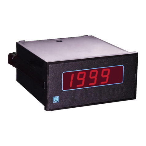
Binding Union
Binding Union METER 44 Technical manual
AEMC
AEMC 721 user manual
IQ Scientific Instruments
IQ Scientific Instruments miniLab IQ128 Elite operating instructions
LI-COR
LI-COR LI-8100A quick start guide

Coatmaster
Coatmaster Atline V4 Operation manual

Endress+Hauser
Endress+Hauser Liquiphant M with FEL56 Functional safety manual
