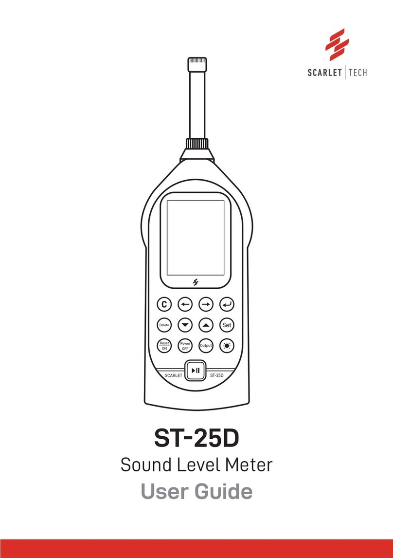
Scarlet Tech ST-11D User manual

ST-11D
User Guide
Sound Level Meter

Precaution
*Please read the manual carefully before using the meter.
*Do not touch any parts of the unit only if necessary for operation.
*Do not disassemble or modify the unit.
*In case of malfunction, do not attempt to do any repairs.
*The warranty doesn’t apply to damage on the meter diaphragm and other improper use.
*Note the condition of the unit clearly and contact the supplier.
*The unit should be protected from shocks and vibration.
*To avoid damage caused by battery leakage, please take out the battery when not
using the meter.
*For storing or operating the unit. Avoid locations which:
1. May be subject to adverse influences such as from high temperature or high humidity,
air with high salt or corrosive content, or gases from chemicals.
2. May be subject to splashes of water or direct sunlight, excessive dust or dirt accumu
lation.

Contents
1. General Introduction
2. Specification
3. Structure features and function
4. Operation before measurement
4.1 Check list
4.2 Use of windscreen
4.3 External power supply
4.4 Check and change of battery
5. Calibration
5.1 Acoustic calibration
5.2 Calibration setup
5.3 Calibration history list
6. Operation of ST-11
6.1 Main menu
6.2 DISP display interface
6.3 List display interface
6.4 “Setup1” submenu
6.4.1 Page 1
6.4.2 Page 2
6.4.3 Page 3
6.4.4 Page 4
6.5 “Setup2” submenu
6.5.1 Starting setup
6.5.2 Auto pause/Restart setup
6.5.3 Hardware setup
6.5.4 Calendar clock adjustment
6.5.5 Logging setup (Optional)
6.5.6 Recording setup (Optional)
6.6 “Data” submenu
6.6.1 Data recall
6.6.2 Clear all
6.6.3 Turn to U disk mode
6.7 Information of instrument
Appendix A
Appendix B
Appendix C
Appendix D
Appendix E: vocabulary of terms
Warranty
1
2
4
7
7
7
7
8
8
9
9
10
10
10
10
11
11
11
12
13
13
14
14
17
17
18
19
19
20
20
22
22
22
24
24
25
26
27
28

General Introduction
Model ST-11D Sound level meter is a digital and multifunction sound level meter with
modular design. Its measurement solution is in accordance with IEC 61672: 2013 Class 1
standard and its sensitivity for emission in radio frequency filed is classified as group X.
The meter has adopted advanced digital detection technology and has automatic range
conversion, reliable and steady performance, wide linear operating range etc. The shell
adopts ABS engineering plastic with beautiful shape, light-weight and is easy to carry.
The power consumption of it is small. Through the RS-232 digital output interface, users
can use a computer remotely to control telemetry, also set a network with computer
control and measurements.
It is applied widely in the measurement of noise produced by various machines, vehicle,
boat, electro etc. Also can be used to measure environmental noise and industrial
noise, e.g. labor protection, industrial hygiene.
Technical Specification
1
LFp, LSp, LIp, Leq1, Lpeak, Leq,T, LFmax,
LFmin, LSmax, LSmin, LImax, LImin,
SEL,Ts, Tm, Volt, E.
Noise Integrating Measurement
LFp, LSp, LIp, Leq,t, Lpeak, Leq,T, LFmax,
LFmin, LSmax, LSmin, LImax, LImin< SEL,
Lex8h, LAVG, TWA, DOSE, Ln1, Ln2, Ln3,
Ln4, Ln5, SD, Ts, Tm, Volt, E.
Stores 8000 groups measurement results
including Timestamp, %Dose, TWA
Sound Level Meter/ Noise Dosimeter/
Data logging & Precision recording(Opt)
IEC 61672:2013 Class 1
10 Hz~20 kHz
27~140 dB
±0.7 dB
0.1dB
A, C, Z, B
F, S, I, Peak
1s~24h
310×72×32 mm
128×64 OLED
0.4kg
4x AAA Batteries or external power supply
AC, DC, RS-232, USB interface
Air temperature: -15°C~+50 °C
Relative humidity: 10 %~90 %
Air pressure: 65 kPa~108 kPa
ST-11/11D Sound Level Meter, Calibration Certificate, Class 1 Field Calibrator (OPTIONAL),
1/2" Prepolarized Condenser Microphone, Windscreen, RS232 Cable, Mini USB Cable
(ST-11D only), User Manual, Waterproof Carrying Case.
-
Fulfils Standard
Normal frequency
Measurement range
Accuracy
Resolution
Frequency Weighting
Time Weighting
Integrating time
Dimensions
Display
Weight
Main Parameters of
Measurement
Datalogging
Power Supply
Output Interface
Application
Operation Environment
Package Contents
ST-11Model ST-11D

Specification
(1) Microphone: Φ12.7mm (1/2'') pre-polarization condenser microphone. Sensitivity:
30mV/Pa. See the Appendix A.
ST-11/11D can also be equipped with other types of microphones to measure noise
which is very low or very high.
(2) Dynamic range
(3) Frequency Range:10Hz∼16kHz, while using the AWA14423 or AWA14431 Micro-
phone, the Frequency Weighting can get to10Hz∼20kHz
(4) Frequency Weighting: A, C, Z and B. For the response in free field, see appendix B.
(5) Time Weighting: F, S, I, Peak
(6) Detectors Characteristics: the true effective value, digital detection, peak factor≧
10.
(7) Accuracy: IEC 61672:2013 Class 1
(8) Range control: high and low two gears, each gear with 20 dB attenuation, reference
level linear range ≧95 dB.
(9) Display: 128×64 OLED
(10) Output interface: AC, DC, RS-232, USB interface
(11) Calibration: use Model ST-120 sound level calibrator to conform specifications of IEC
60942 for Class 1 for the performance class.
(12) Power:
battery 4×LR 6: work at least 6 hours successively.
Lithium battery: work at least 16 hours successively when it is fully charged.
External power: 5V~9V, 0.2A, working current <120mA
Type
AWA14425
AWA14423
AWA14411
AWA14431
Type
AWA14425
AWA14423
AWA14411
AWA14431
A- Weighting
Self-generated
Noise
<20dB(A)
<18dB(A)
<10dB(A)
<40dB(A)
A- Weighting
Self-generated
Noise
<25dB(C)
<23dB(C)
<15dB(C)
<45dB(C)
Z- Weightin
g
<30dB
<28dB
<20dB
<50dB
Meas.
Upper
Range
140dB
138dB
132dB
160dB
External
diameter
(mm)
Φ12.7
Φ12.7
Φ23.77
Φ6.35
Sensitivity
mV/Pa)
30
40
80
4
Frequency
Range (Hz)
10∼16000
10∼20000
10∼16000
10∼20000
Types of microphones
2

Note 1: test conditions based on normal temperature and pressure, and only turn on the
basic functions.
Note 2: when the logging and recording function is open, the consumption of power will
add 40mA.
(13) Dim. (H×W×D) mm: 310 mm×72 mm×32 mm
(14) Weight (kg): 0.4
(15) Operation environment:
Air temperature: -15°C~+50 °C
Relative humidity: 10 %~90 %
Air pressure: 65 kPa~108 kPa
(16) Measurement range:
Above range is the value in the factory, it may change when users tune the calibration
value or replace the microphone. The lower limit is determined by the background noise
plus 8dB.
(17) Main Parameters of Measurement
ST-11D: LFp, LSp, LIp, Leq,t, Lpeak, Leq,T, LFmax, LFmin, LSmax, LSmin, LImax, LImin, SEL,
Lex8h, LAVG, TWA, DOSE, Ln1, Ln2, Ln3, Ln4, Ln5, SD,Ts, Tm, Volt, E.
Note: the n1 to n5 in Ln1-Ln5 can be chosen from 1 to 99.
(18) Memory capacity: 2GB (in ST-11D model)
(19) Logging and recording: optional (in ST-11D model)
(20) Lithium battery (optional): built-in charger module can be charged with 5V external
power supply through USB socket. Use high-capacity lithium battery with 2300mAh
Microphone
Type
AWA14425
AWA14423
AWA14411
AWA14431
Measureme nt
range
(dB)
45∼140
27∼120
43∼138
25∼80
35∼132
15∼112
65∼160
45∼140
Peak
factor
Ref.10
dB
45∼123
27∼103
43∼121
25∼101
35∼115
15∼95
65∼143
45∼123
measurement
range(dB)
70∼143
50∼123
70∼141
50∼121
60∼135
40∼115
90∼163
70∼143
3

Structure features and function
The outline of the Sound Level Meter is shown in figure 1. It consists of microphone,
preamplifier and the main unit. During normal operation, the measuring microphone
and the preamplifier are installed on the head of the main unit, connected with the
main unit through knurled nut. Extension cable can also be used between the main unit
and the preamplifier. The function of the connector’s pin between preamplifier and the
sound level meter is shown in Figure 2. The outline of the sound level meter is sharp to
reduce the reflection of the sound wave. The nominal influence caused by the reflection
on the shell and the indication features under different incidence direction can be
found in Appendix 3. The shell is mold with ABS plastic. The batteries are put in battery
box, which is very convenient for users to replace the batteries just by taking off the
battery cover plate. All switches are button switches and located at the central of the
obverse side. Measuring results are shown on the 128×64 OLED display. Overload
indicator light is located on the front top along with external power supply socket
and USB port see Figure 3.
Fig 1 Fig 2
4

Fig 3
Fig.4 x9 socket
Table 1 Keys function
Power
on/reset
Enter
Exit
Right
cursor
Left
cursor
Parameter
up
Paramet
er down
Power on or reset the meter
Enter the next menu or Input the current
operation
Exit from the current menu or keep pressing for
3s to power off the meter
Move cursor to next position
Move cursor to former position
Parameter data which the cursor points
increases
Parameter data which the cursor points
decreases
Power
Signal Ground
5

AC/DC output socket, the socket is stereo output socket, when matches with the plug,
the definition of each pin plug shown as below:
RS232 output socket, the socket type uses the RJ45 socket, pins are defined as below:
RS232 port serial input, only two serial output signals, the pins are defined as follow:
1.External power:input+4.5V∼9V/output batteries voltage
2.Empty
3.PWM output
4.RXD
5.TXD
6.Reset: at ordinary times should be hung up, heightening level will be reset。
7.Power control: at ordinary times should be hung up, heightening level will turn on
instrument power supply
8.GND
Fig 5. AC and DC output
1
Power
2
Empty
3
PWM
4
RXD
5
TXD
6
Reset
7
Power control
8
GND
AC
DC GND
6

Operation before measurement
Table 2 Definition of symbol
4.1 Check list
①Check whether the microphone has been installed correctly.
②Check whether battery has been put in.
③If necessary, calibrate it with a sound calibrator.
④The meter should be tested by relative department regularly (such as one year) to
ensure its accuracy.
4.2 Use of windscreen
If windy, you may use a windscreen to reduce influence of wind noise. There are differ-
ent types of windscreens to choose. A φ35×60 size windscreen can reduce noise about
10dB-15dB, See Appendix D, the influence of free-field responses for a meter with a
windscreen when there is no wind.
4.3 External power supply
The Sound Level Meter can be connected with external power through the φ1.1 external
power socket at the lower right of the instrument. At this time, the inner battery will be
cut-off automatically. The voltage range of the external power supply is 4.5V~9V. The
shell of plug is the cathode and the core of plug is the anode. When the Sound Level
Meter is used continuously for a long time, it is recommended to use an external power
supply.
Symbol Definition
Battery level display
Microphone setup: diffusion field type
Integrating measurement and statistical
analysis are in progress
Integrating measurement and statistical
analysis are paused
logging the varying waves of SPL with time
Recording
The measured signal surpasses the upper limit
of measurement range
The measured signal under the lower limit of
measurement range
7

Calibration
Fig 6. LR03 batteries
Fig 7. Calibration submenu
Normally, the meter doesn’t need to be calibrated because it had been calibrated before
sale. If it hasn’t been used for a long time, or the microphone is changed or overhauled,
you should calibrate it again.
Move the cursor on “6.Cali.” on the main menu and press key, then enter submenu
of Calibration. See as follows:
There are two kinds of battery: 4×LR03 batteries
or Lithium batteries.
While operating, the meter will check battery
power automatically, if it is low, the under-volt-
age indicator will be lighted up, which reminds
users to change batteries. After changing the
batteries, the meter will operate normally again.
When the lithium batteries are low in power, they
should be powered by the external power supply
with an USB socket.
4.4 Check and change of battery
8

Fig 8. Acoustic calibration of microphone
Fig 9 Calibration setup
First row: Acoustic Calibration. You can use acoustic calibrator to calibrate the sensitiv-
ity of the instrument.
Second row: Calibration Setup. You can set the SPL of the acoustic calibrator or the
sensitivity of the microphone.
Third row: Calibration History of the instrument.
“Lp= dB 94”: The number “94” is the SPL of the calibrator, i.e. the SPL for the instrument
to be calibrated. The data after “Lp=” is the SPL which is measured by the instrument
during the calibration. “Lx= dB -30.0”: The number “-30.0” is the sensitivity level of
microphone. The data after “Lx=” is the newly calibrated sensitivity level of the micro-
phone. Range: 25-120 dBA the lower measurement range with the Lx above.
Move the cursor to the second row on the calibration submenu, press key and
enter calibration setup interface. The following message appears:
“Serial:”: Serial number of the microphone set by the producer. It cannot be modified.
“MIC.Sen.”: Sensitivity level of the microphone. You can adjust the sensitivity level of the
microphone by pressing or key.
“Cali.SPL”: Sound pressure level of the calibrator. If your calibration SPL is not 94.0 dB,
press or key to make it reach the output SPL of the calibrator. Press key
after the adjustment, the instrument will save the operation and display “OK” on the
lower right corner of the screen.
When sound level calibrator is installed on the microphone, turn on the power supply.
Press key to initiate the calibration process. A digit is displaying on the lower right
corner of the screen, which change to 9 from 0 and then pauses, press key and the
new microphone sensitivity level is saved.
Move the cursor on the first row and press key, then you enter the calibration
interface. The display shown as follows:
5.1 Acoustic calibration
5.2 Calibration setup (Use ST-120 Calibrator)
9

Operation of ST-11
Fig 10 Calibration history list
Fig 11. Main menu
Fig 12. DISP interface
Move the cursor on the second row on calibration submenu, and press key to enter
the calibration history list. The following message appears:
One line represents one calibration record. One calibration record includes record time
and the sensitivity level of the microphone. You can view the calibration history of
microphone 1 by pressing or key.
Press key and the instrument will ask you whether to delete the calibration history.
If press key again, all of the calibration histories will be erased.
After pressing key, the instrument does self-check and shows the Host Number,
Microphones Number, Model, and Configuration Number as follows:
Move the cursor to “1.” and press key, the display will show as follows:
5.3 Calibration history list
6.1 main menu
6.2 DISP display interface
10
It takes 10 seconds to do the calibration. Then turn the calibrator ST-120 to 114.0 dB.
Press or key to make it reach the output SPL of the calibrator. Repeat calibra-
tion at the level of 114.0dB.
ST-11
DISP

Fig 13. List interface
Fig 14. Page 1 of Step 1
The cursor can be moved between the “DISP”, “LFp” and “A”, press or key can
change “DISP” to “List” interface. And “LFp” can be changed between these parameters
“LSp”, “Lip”, “Leq, t , “Lpeak”, “Leq, T”, “LFmax”, “LFmin”, “LSmax”, “LSmin”, “LImax” “LImin”,
“SEL”, “Lex8h”, “LAVG”, “TWA”, “DOSE ” “L5”, “ L10”, “ L50”, “ L90”, “ L95” and “SD”.
When the meter doesn’t do integrating measurement, the “Lpeak”, “Leq,T”, “LFmax”,
“LFmin”, “LSmax”, “LSmin”, “LImax” “LImin”, “SEL”, “Lex8h”, “LAVG”, “TWA”, “DOSE”, “L5”, “
L10”, “L50”, “L90”, “L95”, “SD” will be displayed as “0.0”. The symbol “< --” means the
current range is in the low range.
The first three rows show the measurement results. The cursor can be moved to "List",
"C", "LFp", "LSp", "LIp". When cursor is at “C”, press or key can change the
weighting to “Z”; when cursor is at "LFp", "LSp" or "LIp", press or key can
change to other measurement parameters. such as: LFp, LSp, LIp, Leq,t, Lpeak, Leq,T,
LFmax, LFmin, LSmax, LSmin, LImax, LImin, SEL, Lex8h, LAVG, TWA, DOSE, L5, L10, L50,
L90, L95, SD, Ts, Tm, Volt, Date, Time, and E .
The last row “LW” is the logging and sound recording function open.
Note: the logging and sound recording function is the optional function in ST-11D.
6.4.1 Page 1
Move the cursor to “2.Setup1” on the main menu and press key, the instrument will
enter “2.Setup1” interface and display as follows:
When cursor is at “1.” in the main menu, press key, and the instrument will go into
the measurement interface, shown as below:
6.3 List display interface
6.4 “Setup1” submenu
11

Fig 15 Page 2 of Step 1
“Work Mode”:To meet different measurement standards and purposes, ST-11 has
many parameters for you to choose. You can preset the parameters according to the
relevant standards and purposes, divide them into different parameter combinations
and make different names. Then you only need to choose the relevant parameter
combinations for your measurement requests and do not need to set every parameter.
If there are no suitable parameter combinations in the instrument, “----” is displayed
behind and new parameters combinations can be made by PC. ST-11 can store at most
32 parameter combinations. See the operation manual in the instruction of relevant
instrument management software.
“Auto name”: after finishing measurement, it will save and change the group name.
“N/A” means auto name is not available, “yes” means turn on and using this function.
“Name: DATA _0000”: the measurement group name of the results. The former 4 charac-
ters will be kept as the former 4 characters of the file name saved in USB flash disk.
The instrument can save 128 measurement group names at most. You can write new
names by PC.
“P:1”: page 1
The cursor can be moved between “P:”, “Work Mode”, “Auto name”, and “Name”. Press
or key and to be back to the main menu.
Table 2 the cursor location and the relevant available options on page1
Ts=00h00m00s”: preset measuring time. If can be set from 1 second to 24 hours. When
reaches the preset measuring time, the instrument will stop integrating measurement
and statistical analysis, and save the measurement results.
“N:5, 10, 50, 90, 95”: statistical SPL. Statistic sound levels can set the statistic numbers
from 1 ~ 99 at random.
“Sta. weighting” :time weighting when making a statistical analysis.
6.4.2 Page 2
Move the cursor on “P:1” and press key, the instrument will enter page 2 and display as
follows:
Cursor
position
P:
Work
Mode
Auto
Name
Name
Available options
2 or 4
Next prestore
work mode
N/A, Yes
Next prestore
measurement
name
Remarks
Page turning
Choose other
work mode
Whether
automatically
name or not
Recall other
measurement
names
12

Fig 16. Page 3 of Step 1
Fig 17. Page 4 of Step 1
6.4.3 Page 3
Move the cursor on “P:2” and press key when under “2.Setup1” interface, the
instrument will enter page 3 and display as follows:
“Exchange Rate”: exchange rate can be set between 3, 4, 5 and 6.
“Threshold”: the threshold value can be set from 40 to 90dB. If time weighted SPL is less
than the value, it will not participate in TWA, Dose and LAVG calculations.
“Criterion”: the criterion value can be set from 70 to 90dB. Relevant law regulates to
input 8 hours criterion value.
“MIC. Type”: the mode of microphone. Free and Random mode are optional, means free
field type and random incidence type. The ST-11 is equipped with free field microphone
by the producer. If random incidence microphone is requested by some countries’
standards, change the option to “ Random”, so the instrument will automatically modify
the high frequency to meet the request of frequency response of random incidence
microphone.
“Language”: Chinese and English
“Range”: Range of Linearity level.
6.4.4 Page 4
Move the cursor on “P:3” and press key when under “2.Setup1” interface, the
instrument will enter page 4 and display as follows:
Cursor position
P:
h
M
S
5, 10, 50, 90 or 95
Sta. weighting
Available options
3 or 1
01h~24h
01m~59m
01s~59s
Numbers from 1 to 99
F, S, I
Remarks
Page turning
hour
minute
second
Set statistic
sound level
13

Fig 18. Page 1 of Step 2
Fig 19. Page 2 of Step 2
Fig 20. Page 3 of Step 2 with authorization
Fig 21. Page 3 of Step 2 without authorization
Move the cursor on “4.Setup2” and press key when on the main menu, the instru-
ment will enter page 1 under “4.Setup2” interface and display as follows:
“2.Setup2” is for setting of starting mode, auto-pause, restart, hardware, power supply,
clock, logging and recording. Move the cursor on “P:1”, then press or key and
enter page 2. The screen displays as follows:
If the user already has authorization of data logging and recording software, move the
cursor to “P:2”, press or key and enter page3. The screen displays as follows:
Otherwise it will remind user to input a 14 bit authorization code.
When on page 1 under setup 2 interface, move the cursor to the first row, press key
and enter starting setup interface. The screen displays shown as follows:
6.5 “2.Setup2” submenu
6.5.1 Starting setup
14

Fig 22. Starting setup
Fig 23. Starting setup of clock
Fig 24. Starting setup of button
“Source”: trigger source, including Clock, Button, Equivalent interval, Limit-surpassing
and serial. Applications of each trigger source are listed in the Table 3:
When choosing “Clock”, “Date” and “Time” are displayed on the screen. You can preset a
certain time, and when the preset time is reached, the instrument will automatically
start measuring. You can move the cursor on Year, Month, Day, Hour, Minute and Second
either, and use or key to adjust the time. When a parameter reaches its end, it
displays “**” which means the parameter does not participate in comparison. The
instrument can be triggered once an hour, once a day, or once a month.
When choosing “Button”, the screen displays as follows:
Table 3 Applications of the trigger sources
6.5.1.1 The timing start
6.5.1.2 Button start
No
1
2
3
4
5
Source
Clock
Button
Equivalent
interval
Limit-surpassing
serial
Remarks
Start when reach the specified time
Start by pressing the Button
Start when each time measurement
has the equivalent intervals
Start when the current value exceeds
the specified limit value
Continuously measure
15

Fig 25. Starting setup of interval
Fig 26. Starting setup of limit
Fig 27. Continuous measurement
“Run Delay”: delay time for starting measurement can be set after pressing key. If
0s is chosen, is the measurement will start right away.
Note:Though some certain trigger mode is chosen, you can still start measurement by
pressing key while on “1.Meas”submenu interface.
When choose “Equivalent interval”, the instrument displays as follows:
“Delta_T”: interval time for each starting measurement, which can be set between 1min,
5min, 10min, 20min, 30min and 1hour. For example “5 min” means starting at every 5
minutes.
Note: when Ts is longer than this interval, the actual measurement time is according to
Ts and the starting time will be delayed.
“Value”: the preset limit value. If the value is being exceeded, the instrument will start
measuring. The value can be set between 40 ~140.
“Delay”: the continuous limit-surpassing time. The instrument starts measurement
when the time-weighted average index SPL for analysis of channel 0 surpasses the
limit. The measurement will continue when the accumulated limit-surpassing time
exceeds the “Delay” value, otherwise it will stop. The value can be set from 0 to 999s.
When choose “Limit”, the instrument displays as follows:
When choose “serial”, the display shows as follows:
6.5.1.3 Equivalent interval activation
6.5.1.4 Limit-surpassing start
6.5.1.5 Serial measurement
16

Fig 28. Auto pause/Restart setup
Fig 29. Hardware setup
“First Ts”: the measurement time for each group, the time can be set by user or choose
between 1min, 5mim, 10min, 20min, 30min and 1hour.
“Total”: the total groups of continuous measurement. The number can be set from 1 to
1440.
Note:When enter restart interface, “Restart clock” is displayed on the bottom row.
“Mode”: working mode of auto pause or restart setup which can be chosen between N/A
and Clock. When N/A is chosen, the instrument will not pause or restart. When Clock is
chosen, the instrument will auto pause or restart when the internal clock reaches at
the fixed time.
“Date”: the fixed date for auto pause/ restart
“Time”: the fixed time for auto pause/restart
You can move the cursor on Year, Month, Day, Hour, Minute and Second either, and use
or key to adjust the time. When a parameter reaches its end, it displays “**”
which means the parameter does not participate in comparison when auto-on or
auto-off. The instrument can switch on or off once an hour, once a day, once a month……
It is suggested to use Auto pause or Restart function together with Timed Activation
function to make automatic measurement.
Move the cursor to the second and third row under “setup 2” interface and press
key, then enter Auto pause / Restart setup interface.
Move the cursor to the “hardware” on page 2 under “setup 2” interface. Press then it
displays as follows:
The first line shows the amplitude of AC output and frequency weighting. The second
row shows whether the instrument will turn off automatically for a long time without
any operation. The third row shows the indicator lamp light specified threshold. The
fourth row shows the baud rate of serial port. The cursor can be moved to “AC”, “W”,
“Auto-off”, “Limit” and “Baud rate”.
6.5.2 Auto pause/Restart setup
6.5.3 Hardware setup
17
Table of contents
Other Scarlet Tech Measuring Instrument manuals
Scarlet Tech
Scarlet Tech WL-410 User manual

Scarlet Tech
Scarlet Tech ST-130 User manual

Scarlet Tech
Scarlet Tech WindPro User manual

Scarlet Tech
Scarlet Tech ST-109 User manual

Scarlet Tech
Scarlet Tech TWL-1S User manual
Scarlet Tech
Scarlet Tech ST-109 User manual

Scarlet Tech
Scarlet Tech ST-25D User manual

Scarlet Tech
Scarlet Tech WR-3 Plus User manual
Scarlet Tech
Scarlet Tech WR-3 User manual