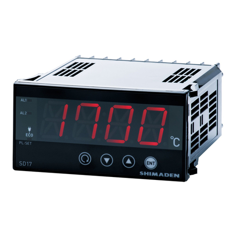
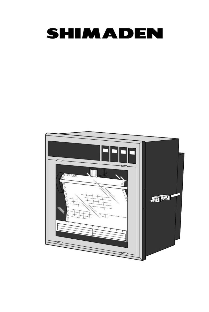
Shimaden SD24 Series User manual

MSD24-E01-A
October 2009
1 Copyright © SHIMADEN CO., LTD. All rights reserved.
Digital Indicator
SD24 Series
Instruction Manual
Please be sure to provide the end user with these instructions.
Preface
Thank you for purchasing a Shimaden product.
After making sure the product you have is the one you specified, get a good understanding of the instructions to ensure proper
operation and handling.
This document contains precautions, mounting method, wiring/function descriptions and operation method for those involved
in wiring, installing and performing routine maintenance for the SD24 Series.
Keep the instructions in a handy place when operating/handling the SD24 Series and be sure to adhere to the instructions
contained herein.
Safety precautions and precautions concerning equipment damage and other additional explanations are provided under the
following labeling.
WARNING Matters that could result in injury or death if instructions are not followed.
Caution Matters that could result in equipment damage if instructions are not followed.
Note Additional explanations or matters requiring special attention.
Safety precautions
WARNING
The SD24 Series digital indicators are designed to indicate temperature, humidity and other physical amounts for general industrial
equipment. You should either take appropriate safety measures or avoid using for control that could have a serious effect on human life.
The digital indicator should be housed in the control box, etc., to keep the terminal elements from being accidentally touched.
Do not remove the indicator from its case, or insert your fingers or electric conductors inside the case. Doing so could result in electric
shock accident involving death or serious injury.
Caution
If there is danger of damage to any peripheral device or equipment due to failure of the indicator, you should take appropriate safety
measures such as mounting a fuse or overheating prevention device.
An alert symbol is printed on the terminal nameplate applied to the case. Alert marks are provided to call your attention to the fact
that you could be shocked if you touch charged parts.
Provide a switch or breaker as a means of cutting off power for external power circuit connected to the power terminal of the indicator.
Mount a switch or breaker near the indicator where the operator can get to it easily and label it as an electrical breaker for the indicator.

2
Fuses
The indicator does not have a built-in fuse. Be sure to mount a fuse on the power circuit connected to the power terminal.
Provide a fuse between the switch or breaker and the indicator. Mount on the L side of the power terminal.
Fuse rating/characteristics: 250V AC, 1.0A/medium or slow blowing
Voltage/current of load connected to the output terminal (analog output) and alert terminal should be within the rating.
Using voltage/current that exceeds the rating could shorten the life of the product by raising the temperature, and could result in
equipment failure.
For rating, see “8. Specifications."
Connect equipment that conforms to requirements for IEC61010-1 to the output terminal.
Do not apply voltage/current other than rated input to the input terminal. Doing so could shorten the life of the product or result in
equipment failure.
For rating, see “8. Specifications."
If the input is voltage (mV or V) or current (mA), connect equipment that conforms to IEC61010-1 to the input terminal.
Be careful not to allow foreign matter such as metal to get into the draft holes for heat dissipation. Doing so could result in equipment
failure or fire.
Do not allow the draft holes to become clogged with dust, etc. Doing so could shorten the life of the product due to temperature rise or
insulation deterioration, and could result in equipment failure. For space between instruments to be mounted, see “2.3 External
dimensions and panel cutout.”
Note that repeating endurance tests such as dielectric strength, noise resistance and surge resistance could negatively affect the
indicator.
The user should absolutely not modify or use the indicator other than the way it was intended.
Contents
1. Introduction...........................................................................................3
1.1 Preliminary check ..............................................................................3
1.2 Precautions when using .....................................................................3
2. Installation and wiring .........................................................................4
2.1 Installation site (environmental conditions).......................................4
2.2 Installation .........................................................................................4
2.3 External dimensions and panel cutout ...............................................4
2.4 Wiring ................................................................................................4
2.5 Terminal layout ..................................................................................5
3. Front panel ............................................................................................5
3.1 Parts ...................................................................................................5
3.2 Description.........................................................................................6
4. Error messages......................................................................................6
5. Screen.....................................................................................................7
5.1 Screen sequence.................................................................................7
5.2 Power on screen group.....................................................................10
5.3 Mode 0 screen group........................................................................10
5.4 Mode 1 screen group........................................................................11
5.5 Mode 2 screen group........................................................................14
6. Function...............................................................................................16
6.1 Maximum value (MAX) / minimum value (MIN)...........................16
6.2 Hold function...................................................................................16
6.3 DI function.......................................................................................16
7. Optional functions ..............................................................................17
7.1 Alarm output ....................................................................................17
7.2 Analog output...................................................................................18
7.3 Setting the square-root extraction function......................................19
7.4 10-segment linear approximation ....................................................19
7.5 Sensor DC power supply .................................................................20
8. Specifications.......................................................................................21

3
1. Introduction
1.1 Preliminary check
The equipment undergoes a thorough quality inspection before shipment from the factory. You should however make sure
there is nothing wrong with the specification code, appearance or accessories.
Specification code check
Compare the specification code on the case with the following to make sure it is the product you ordered.
Item Code Specifications
1. Series SD24 - 48 x 96 DIN size digital indicator, DI 2 points
8
Multi input
• Thermocouple
• R.T.D. (Pt100, JPt100)
• Voltage (mV)
Input resistance: 500kΩmin.
For details concerning input types and measuring range, see "8.
Specifications measuring range codes.”
Inverse scaling possible for voltage (mV) (Note 1)
6 Voltage (V) DC
Input resistance: 500KΩmin.
2. Input
4
Current (mA) DC
Internal receiving impedance:
250Ω
Inverse scaling possible (Note 1)
90- 100 – 240V AC±10% (50/60Hz)
3. Power
08- 24V AC (50/60Hz) / DC ±10%
0 Without
1
Output 4 points (AL1/AL2/AL3/AL4、contact a)
(AL1/AL2 and AL3/AL4 are COM shared)
Contact capacity 240V AC, 2A / resistive load
4. Alarm output (optional)
2 Output 2 points (AL1/AL2, contact c)
Contact capacity 240V AC, 2.5A / resistive load
00 Without
03 0 – 10mV DC, output resistance 10Ω
04 4 – 20 mA DC, load resistance 300Ωmax.
06 0 – 10V DC, load current 2 mA max.
Inverse scaling possible
(within measuring range)
50 RS-485
5. Analog output/communication
(optional) (Note 2)
70 RS-232C
0 Without
6. DC power supply for sensor
(optional) 1 24V DC, 50 mA
0 Without
7. Remarks
9 With (Please consult before ordering.)
* Note 1 Scaling range: -9999 – 30000 unit
Span: 10 – 40000 unit
* Note 2 Select either analog output or communication
Accessories check
Unit seal: 1
Communication instruction manual: 1 (if optionally equipped with communication)
Note In the event you want to inquire about a product defect, missing accessory or other matter, please contact your
nearest Shimaden agent.
1.2 Precautions when using
Do not operate the front panel keys with hard or pointed objects. Always press the keys lightly with the tips of your fingers.
To clean, wipe lightly with a dry cloth. Do not use solvents such as thinner.

4
2. Installation and wiring
2.1 Installation site (environmental conditions)
Caution
Do not use in the following locations. Doing so could lead to equipment failure, damage or fire.
• Places exposed to flammable or corrosive gases, oil mist, or excessive dust that could cause insulation to deteriorate
• Places where ambient temperature may fall below -10°C or rise above 50°C
• Places where ambient humidity may exceed 90% RH or places subject to condensation
• Places subject to strong vibration or impact
• Places near strong electric circuit or places subject to inductive interference
• Places exposed to water dripping or direct sunlight
• Places where altitude exceeds 2000 m
Note Among environmental conditions, IEC60664 installation category II, pollution class 2.
2.2Installation
1)
Cut a hole for mounting the indicator by referring to the cutout drawing in section 2.3. The panel thickness should be 1.0 – 4.0 mm.
2) The indicator is provided with tabs for mounting. Insert as is from the front surface of the panel.
Note SD24 indicators are panel mounted indicators.
Be sure to mount on the panel.
2.3 External dimensions and panel cutout
External dimensions
Unit: mm
Panel cutout
Unit: mm
2.4Wiring
WARNING
Do not supply power when wiring. Doing so could result in electrical shock. Be sure to ground the protective conductor terminal ( ).
Failure to ground could result in electrical shock. After wiring, do not touch terminal elements or other charged parts while conducting
electricity.
DISP
3 4
MAX MIN
SET
HOLD

5
Be sure to wire in accordance with "2.5 Terminal layout."
Use a crimp-type terminal that matches an M3.5 screw and is no wider than 7 mm.
For thermocouple input, use a compensating conductor that matches the type of thermocouple.
Arrange so that external resistance does not exceed 100Ω.
For R.T.D. input, resistance for lead wires should be a maximum of 5Ωper wire. All 3 wires should have the same resistance.
Input signal wires must not be accommodated with a strong electric circuit in the same conduit or duct.
Using shielded wiring (single point grounding) is effective for static induction noise.
Making input wiring short and twisting at regular intervals is effective for electromagnetic induction noise.
For power supply, use wiring or cable with sectional area of at least 1 mm² that offers the same performance as 600V vinyl
insulated wiring.
The ground wire should be at least 2 mm² and the ground resistance should not exceed 100Ω.
The symbol indicates the location of the function ground terminal. Ground if possible to avoid the effect of noise, etc.
Securely fasten the terminal element screw.
Fastening torque: 1.1N · m (11kgf · cm)
Noise filter
If the instrument appears to be easily affected by power supply noise, use a noise filter to prevent malfunctioning.
Mount the noise filter on the grounded panel and make the wire connection between the noise filter output and power line
terminals of the indicator as short as possible.
2.5Terminallayout
Note Do not connect an input other than the stipulated input to the terminals.
3. Front panel
3.1Parts
Front panel

6
3.2 Description
cMonitor LED
MAX: Maximum PV value display monitor LED (green)
Lights when maximum PV value is displayed.
MIN: Minimum PV value display monitor LED (green)
Lights when minimum PV value is displayed.
HOLD: Hold PV value display monitor LED (green)
Lights when hold PV value is displayed.
COM/SET: Communication / parameter setting monitor LED (green)
Lights when in the communication mode.
Flickers on/off for mode 1 and mode 2 screen groups.
AL1: Alarm 1 output monitor LED (red)
Lights when alarm 1 is output.
AL2: Alarm 2 output monitor LED (red)
Lights when alarm 2 is output.
AL3: Alarm 3 output monitor LED (red)
Lights when alarm 3 is output.
AL4: Alarm 4 output monitor LED (red)
Lights when alarm 4 is output.
dMeasured value display LED (red)
Displays current parameter PV value on basic screen (screen 0-0).
Displays and sets parameters for each mode screen group.
eKey switch operation section
Display key
Switches PV display from current value →maximum value →minimum value →current value.
Parameter key
Pressing this key displays the next display screen.
Toggles between mode 0 screen group and mode 1 screen group.
Press and hold for approximately 2 seconds to switch from 0-0 to 1-0 screen group and vice versa.
Down key
Decrements parameter values on the setting screens.
The decimal point of the lowest digit flickers on/off until the value is entered by the ENT key.
Up key
Increments parameter values on the setting screens.
The decimal point of the lowest digit flickers on/off until the value is entered by the ENT key.
ENT (enter) key
Enters parameters modified by the up and down keys on the setting screens.
Toggles between display and setting screens. When doing so, the decimal point of the lowest digit stops
flickering on/off.
4. Error messages
The following error messages are displayed on the basic screen (0-0):
When any of the following occurs
cBreak in thermocouple input wiring
dBreak in R.T.D. input A wiring
eIf PV value exceeds higher limit of measurement range by approximately 10%
fIf scaling value exceeds 32,000 for voltage or current input
If PV value falls below lower limit of measurement range by approximately 10%
If cold junction (CJ) is abnormal on higher limit side during thermocouple input
If cold junction (CJ) is abnormal on lower limit side during thermocouple input
If B of R.T.D. (terminal No. kor l) is broken or if A, B or more than one B is broken

7
Screen always displayed
Screen displayed under certain conditions
Screen displayed when equipped with optional items
The following conditions are indicated by the screen
frame display:
Model
Power on screen group
Input type
Measuring range
lower limit value
Measuring range
higher limit value
Basic screen
(PV current value)
0-0
Alarm 1
Latching release
0-1
Alarm 2
Latching release
0-2
0-3
0-4
PV bias
0-5
PV filter
0-7
Alarm 1
Setting value
0-8
0-9
Alarm 2
Setting value
Alarm 3
Setting value
0-10
0-11
Alarm 4
Setting value
PV max. value PV min. value
PV slope
0-6
Alarm 3
Latching release
Alarm 4
Latching release
0-0
To basic screen
Mode 0 screen group
1-0
To 1-0 screen
Approx. 2 seconds
Key operation for power on screen group
The screens of the power on screen group change automatically
and therefore do not require key operation. Displays input type and
measuring range set for the device.
Key operation for mode 0 screen group
The mode 0 screen group consists of items that are used frequently
during operation. The main key operations are as follows.
Key operation for mode 1 and 2 screen group
Consists of setting screens, etc., that are not used as frequently as
the 0 screen group and are modified as needed according to input
condition, control, etc.
The main key operations are as follows.
Auto return function
Automatically switches back to basic screen if not key operation is
performed for 3 minutes when screen other than basic screen
(screen 0-0) is displayed.
・Advance display screen.
・Switch from 0-0 screen to 1-0 screen.
Press and hold approx. 2 seconds.
・Switch back to display screen from setting screen.
・Switch from display screen to setting screen.
・Advance display screen.
・Switch back to display screen from setting screen.
・Switch from display screen to setting screen.
・Move back display screen.
+
・Switch back to initial screen of mode screen from
either mode 1 or 2 screen.
+
Switch back to 0-0 screen.
・Switch back from 1-0 screen to 0-0 screen.
Press and hold approx. 2 seconds.
5. Screen
5.1 Screen sequence

8
Measuring range
Scaling
decimal places
Scaling
lower limit value
Scaling
higher limit value
Alarm 1
Hysteresis
Alarm 1
Standby action
Alarm 2
Hysteresis
Alarm 2
Standby action
Alarm 3
Hysteresis
Alarm 3
Standby action
Alarm 4
Code
1-17
Alarm 4
Hysteresis
1-18
Alarm 4
Standby action
1-19
Analog output
Scaling lower limit
1-21
Communication
mode
1-25
Communication
protocol
1-26
Communication
address
1-27
Communication
data
1-28
Start character
1-29
BCC
operation
1-30
Communication
speed
1-31
Delay time
1-32
1-22
Analog output
Scaling higher limit
DI1 allocation
1-23
1-24
DI2 allocation
Mode 1 initial screen
1-0
Key lock
1-1
1-2
1-3
Input unit
1-4
1-5
1-6
1-7
Alarm 1
Code
1-8
1-9
1-10
Alarm 2
Code
1-11
1-12
1-13
Alarm 3
Code
1-14
1-15
1-16
1-0
To 1-0 screen
2-0
To 2-0 screen
Approx. 2
seconds
0-0
To 0-0 screen
Last digit past
decimal point
Analog output
Hold function
1-20
1-33
Communication
memory mode

9
Mode 2 initial screen
2-0
Square-root
extraction
2-2
Low cut
2-3
Linear approximation
ON/OFF
2-4
Linear approximation
A1
2-5
Linear approximation
B10
2-24
Linear approximation
B1
2-6
Linear approximation
A10
2-23
Linear approximation
B11
2-26
Linear approximation
A11
2-25
Source frequency
2-1
Linear approximation
A2
2-7
Linear approximation
B2
2-8
Linear approximation
A3
2-9
Linear approximation
B3
2-10
Linear approximation
A4
2-11
Linear approximation
B4
2-12
Linear approximation
A5
2-13
Linear approximation
B5
2-14
Linear approximation
A6
2-15
Linear approximation
B6
2-16
Linear approximation
A7
2-17
Linear approximation
B7
2-18
Linear approximation
A8
2-19
Linear approximation
B8
2-20
Linear approximation
A9
2-21
Linear approximation
B9
2-22
2-0
To 2-0 screen
1-0
To 1-0 screen

10
5.2 Power on screen group
The following information is automatically displayed when the
power is turned on.
The example shows the information when shipped from the factory.
Product name
Indicates product name (SD24).
Input
Indicates type of input.
TC (thermocouple), Pt (R.T.D.), mV, V or mA
Measuring range lower limit value
Indicates input measuring range lower limit
value.
Measuring range higher limit value
Indicates input measuring range higher limit
value.
5.3Mode0screengroup
The following information icons are used here to facilitate explanation.
Setting/display enable
when optionally equipped
with alarm
Setting/display enable
when optionally equipped
with analog output
Setting/display enable
when optionally equipped
with communication
Setting/display enable
when using
voltage/current input for
measuring range
Setting/display unable
when using
voltage/current input for
measuring range
Setting range Initial value
0-0 Basic screen
Displays PV value.
Note Press to display maximum (MAX) or minimum (MIN) value.
0-1 Alarm 1 unlatching
Indicates alarm 1 status. Can be unlatched.
Sets alarm 1 code to type with latching function
(screen 1-8) and indicates when latched. To
reset alarm output, set to RSET.
For more information on the latching function,
see 7.1 Latching function for alarm output.
KEEP: Latch
RSET: Unlatch
KEEP, RSET KEEP
0-2 Alarm 2 unlatching
Indicates alarm 2 status. Can be unlatched.
Sets alarm 2 code to type with latching
function (screen 1-11) and indicates when
latched. To reset alarm output, set to RSET.
For more information on the latching function,
see 7.1 Latching function for alarm output.
KEEP: Latch
RSET: Unlatch
KEEP, RSET KEEP
0-3 Alarm 3 unlatching
Indicates alarm 3 status. Can be unlatched.
Sets alarm 3 code to type with latching function
(screen 1-14) and indicates when latched. To
reset alarm output, set to RSET.
For more information on the latching function,
see 7.1 Latching function for alarm output.
KEEP: Latch
RSET: Unlatch
KEEP, RSET KEEP
0-4 Alarm 4 unlatching
Indicates alarm 4 status. Can be unlatched.
Sets alarm 4 code to type with latching
function (screen 1-17) and indicates when
latched. To reset alarm output, set to RSET.
For more information on the latching function,
see 7.1 Latching function for alarm output.
KEEP: Latch
RSET: Unlatch
KEEP, RSET KEEP
0-5 PV bias setting
Sets/displays PV bias value.
This value is used to offset input error of
sensors, etc. When set, displays offset value.
-9999 – 10000 unit 0 Unit
0-6 PV slope setting
Sets/displays PV slope value.
This value is used to offset input error of
sensors, etc. When set, displays offset value.
0.500 – 1.500 1.000
0-7 PV filter setting
Sets/displays PV filter time.
This value helps control the effect of PV
input noise.
Note PV filter is temporarily ineffective when resetting from scale over.
0 – 100 seconds 0
0-8 Alarm 1 setting value
Alarm type set by alarm 1 code (screen 1-8) is
displayed. Set the alarm setting values.
The second and third from last dots light when
the latching function is employed.
A1HA : Higher limit absolute value
A1LA : Lower limit absolute value
A1H.A. : Higher limit absolute value
(with latching function)
A1L.A. : Lower limit absolute value
(with latching function)
Note Screen is not displayed when alarm 1 code (screen 1-8) is "non" (none)
or in the case of So (scale over).
See 8. Specifications Setting Range
Refer to initial values.
m
V
V
m
A
m
V
V
m
A

11
0-9 Alarm 2 setting value
Alarm type set by alarm 2 code (screen 1-11)
is displayed. Set the alarm setting values.
The second and third from last dots light when
the latching function is employed.
A2HA : Higher limit absolute value
A2LA : Lower limit absolute value
A2H.A. : Higher limit absolute value
(with latching function)
A2L.A. : Lower limit absolute value
(with latching function)
A2dHi : Deviation higher limit value
A2dLo : Deviation lower limit value
A2dHL : Deviation higher/lower limit value
A2d.H.i : Deviation higher limit value
(with latching function)
A2d.L.o : Deviation lower limit value
(with latching function)
A2d.H.L : Deviation higher/lower limit value
(with latching function)
Note Screen is not displayed when alarm 2 code (screen 1-11) is "non" (none)
or in the case of So (scale over).
See 8. Specifications Setting Range
Refer to initial values.
0-10 Alarm 3 setting value
This screen is not displayed when contact c
alarm is selected.
Alarm type set by alarm 3 code (screen 1-14)
is displayed. Set the alarm setting values.
The second and third from last dots light when
the latching function is employed.
A3A : Higher limit absolute value
A3LA : Lower limit absolute value
A3H.A. : Higher limit absolute value
(with latching function)
A3L.A. : Lower limit absolute value
(with latching function)
Note Screen is not displayed when alarm 3 code (screen 1-14) is "non" (none)
or in the case of So (scale over).
See 8. Specifications Setting Range
Refer to initial values.
0-11 Alarm 4 setting value
This screen is not displayed when contact c
alarm is selected.
Alarm type set by alarm 4 code (screen 1-17)
is displayed. Set the alarm setting values.
The second and third from last dots light when
the latching function is employed.
A4HA : Higher limit absolute value
A4LA : Lower limit absolute value
A4H.A. : Higher limit absolute value
(with latching function)
A4L.A. : Lower limit absolute value
(with latching function)
A4dHi : Deviation higher limit value
A4dLo : Deviation lower limit value
A4dHL : Deviation higher/lower limit value
A4d.H.i : Deviation higher limit value
(with latching function)
A4d.L.o : Deviation lower limit value
(with latching function)
A4d.H.L : Deviation higher/lower limit value
(with latching function)
Note Screen is not displayed when alarm 4 code (screen 1-17) is "non" (none)
or in the case of So (scale over).
See 8. Specifications Setting Range
Refer to initial values.
5.4Mode1screengroup
1-0 Mode 1 initial screen
First screen of the mode 1 screen group.
1-1 Key lock
Sets/displays key lock status.
The concerned parameter data cannot be
modified when key lock is set to ON.
OFF : All keys can be operated.
LOCK1: Only key lock and mode 0 screen
group parameters can be modified.
LOCK2: Only key lock can be modified.
OFF, LOCK1, LOCK2 OFF
1-2 Measuring range
Sets/displays type of input. For details on
selections, see 8. Specifications Measuring
Range Codes.
Note
When measuring range is modified, the contents of all parameters are
initialized. Be careful when doing so. Measuring range display type
varies according to the required product specifications. If the necessary
range code does not appear, see the specification code.
See 8. Specifications Setting Range
05 (Universal-input)
86 (Voltage input)
95 (Current input)
1-3 Decimal point last digit switch
Sets/indicates whether or not last digit past
the decimal point decided by the range code
is to be displayed.
norm: Displays measuring range indicated in
measuring range code table.
Shrt : Rounds off the last digit of the measuring
range indicated in the measuring range
code table; digits below the decimal point
are not displayed.
Note
If set to "Shrt," the last digit of input scaling, analog output scaling,
alarm setting value, hysteresis, and PV bias are rounded off. If changed
from "Shrt," to "norm," the last digit of input scaling, analog output
scaling, alarm setting value, hysteresis, and PV bias are set to zero.
norm, Shrt norm
1-4 Input unit
Sets/displays input unit.
℃,
℃
1-5 Input scaling decimal point position
Sets/displays scaling decimal point position
for voltage/current input.
Note In case other than voltage/current input (Thermocouple and R.T.D. input)
only displays scaling decimal position.
nnnn. – n.nnn n.nn
1-6 Input scaling lower limit value
Sets/displays scaling lower limit value for
voltage/current input.
Note
In case other than voltage/current input (Thermocouple and R.T.D. input)
only displays scaling lower limit value. Span between lower and higher
limit values is 10 – 40,000. Inverse scaling is possible.
-9999 – 30000 unit 0 unit
m
V
V
m
A
m
V
V
m
A

12
1-7 Input scaling higher limit value
Sets/displays scaling higher limit value for
voltage/current input.
Note
In case other than voltage/current input (Thermocouple and R.T.D. input)
only displays scaling higher limit value. Span between lower and higher
limit values is 10 – 40,000.
Inverse scaling is possible.
-9999 – 30000 unit 10000 unit
1-8 Alarm 1 code
Sets/displays type of alarm 1 action.
For details on various types of action, see 7.1
Types of action for alarm output.
non :None
HA :Higher limit absolute value
LA :Lower limit absolute value
HA_L :Higher limit absolute value
(with latching function)
LA_L :Lower limit absolute value
(with latching function)
So :Scaleover
Note
If alarm code is modified, hysteresis, standby action and alarm setting
value are reset. The values are however not reset if HA is changed to
HA_L or vice versa, or LA is changed to LA_L or vice versa.
non, HA, LA, HA_L, LA_L, So HA
1-9 Alarm 1 hysteresis
Sets/displays alarm hysteresis.
Note Screen is not displayed when alarm 1 code (screen 1-8) is non or in the
case of So.
1 – 9999 unit 20 unit
1-10 Alarm 1 standby action
Sets/displays type of alarm 1 standby action.
Note Screen is not displayed when alarm 1 code (screen 1-8) is non or in the
case of So.
OFF, ON OFF
1-11 Alarm 2 code
Sets/displays type of alarm 2 action.
For details on various types of action, see 7.1
Types of action for alarm output.
non : None
HA : Higher limit absolute value
LA : Lower limit absolute value
HA_L : Higher limit absolute value
(with latching function)
LA_L : Lower limit absolute value
(with latching function)
So : Scaleover
The following are not displayed when alarm
code is non or So.
dHi : Deviation higher limit value
dLo : Deviation lower limit value
dHL : Deviation higher/lower limit value
dHi_L : Deviation higher limit value
(with latching function)
dLo_L : Deviation lower limit value
(with latching function)
dHL_L : Deviation higher/lower limit value
(with latching function)
Note
Setting contents are initialized if alarm code is modified. The values are
however not initialized if HA is changed to HA_L, LA is changed to LA_L,
dHi is changed to dHi_L, dLo is changed to dLo_L, dHL is changed to
dHL_L or vice versa. The deviation setting is the value relative to alarm 1.
non, HA, LA, HA_L, LA_L, So
dHi, dLo, dHL, dHi_L, dLo_L,
dHL_L
LA
1-12 Alarm 2 hysteresis
Sets/displays alarm 2 hysteresis.
Note Screen is not displayed when alarm 2 code (screen 1-11) is non or in the
case of So.
1 – 9999 unit 20 unit
1-13 Alarm 2 standby action
Sets/displays type of alarm 2 standby action.
Note Screen is not displayed when alarm 2 code (screen 1-11) is non or in the
case of So.
OFF, ON OFF
1-14 Alarm 3 code
This screen is not displayed when contact c
alarm is selected.
Sets/displays type of alarm 3 action.
For details on various types of action, see 7.1
Types of action for alarm output.
non :None
HA :Higher limit absolute value
LA :Lower limit absolute value
HA_L :Higher limit absolute value
(with latching function)
LA_L :Lower limit absolute value
(with latching function)
So :Scaleover
Note
Setting contents are reset if alarm code is modified. The values are
however not reset if HA is changed to HA_L or vice versa, or LA is
changed to LA_L or vice versa.
non, HA, LA, HA_L, LA_L, So non
1-15 Alarm 3 hysteresis
This screen is not displayed when contact c
alarm is selected.
Sets/displays alarm 3 hysteresis.
Note Screen is not displayed when alarm 3 code (screen 1-14) is non or in
the case of So.
1 – 9999 unit 20 unit
1-16 Alarm 3 standby action
This screen is not displayed when contact c
alarm is selected.
Sets/displays type of alarm 3 standby action.
Note Screen is not displayed when alarm 3 code (screen 1-14) is non or in the
case of So.
OFF, ON OFF
m
V
V
m
A

13
1-17 Alarm 4 code
This screen is not displayed when contact c
alarm is selected.
Sets/displays type of alarm 4 action.
For details on various types of action, see 7.1
Types of action for alarm output.
non : None
HA : Higher limit absolute value
LA : Lower limit absolute value
HA_L : Higher limit absolute value
(with latching function)
LA_L : Lower limit absolute value
(with latching function)
So : Scaleover
The following are not displayed when alarm
code 3 is non or So.
dHi : Deviation higher limit value
dLo : Deviation lower limit value
dHL : Deviation higher/lower limit value
dHi_L : Deviation higher limit value
(with latching function)
dLo_L : Deviation lower limit value
(with latching function)
dHL_L : Deviation higher/lower limit value
(with latching function)
Note
Setting contents are initialized if alarm code is modified. The values are
however not initialized if HA is changed to HA_L, LA is changed to LA_L,
dHi is changed to dHi_L, dLo is changed to dLo_L, dHL is changed to
dHL_L or vice versa. The deviation setting is the value relative to alarm 3.
non, HA, LA, HA_L, LA_L, So
dHi, dLo, dHL, dHi_L, dLo_L,
dHL_L
non
1-18 Alarm 4 hysteresis
This screen is not displayed when contact c
alarm is selected.
Sets/displays alarm 4 hysteresis.
Note Screen is not displayed when alarm 4 code (screen 1-17) is non or in the
case of So.
1 – 9999 unit 20 unit
1-19 Alarm 4 standby action
This screen is not displayed when contact c
alarm is selected.
Sets/displays type of alarm 4 standby action.
Note Screen is not displayed when alarm 4 code (screen 1-17) is non or in the
case of So.
OFF, ON OFF
1-20 Analog output hold function
Analog output selection when hold is
employed. Selects whether to output the
value when hold is employed or to output the
current value regardless of the value when
hold is employed.
OFF : Outputs current PV value.
ON : Outputs hold value.
OFF, ON OFF
1-21. Analog output scaling lower limit value
Sets/displays scaling lower limit value of
analog output.
Note
Inverse scaling is possible.
The same value cannot be set for both higher limit value and lower limit
value (screen 1-22).
Measuring range lower limit
value - higher limit value
Lower limit value
1-22 Analog output scaling higher limit value
Sets/displays scaling higher limit value of
analog output.
Note
Inverse scaling is possible.
The same value cannot be set for both higher limit value and lower limit
value (screen 1-21).
Measuring range lower limit
value - higher limit value
Higher limit value
1-23 DI1 code
Sets/displays type of DI1 action.
non : None
HLd : Hold function
(when holding current input)
rSt : Resets maximum value (MAX)
and minimum value (MIN).
L_rS : All unlatch
Note The same type of action as the DI2 setting (other than non) cannot be
selected.
non, HLd, rSt, L_rS HLd
1-24 DI2 code
Sets/displays type of DI2 action.
non : None
HLd : Hold function
(when holding current input)
rSt : Resets maximum value (MAX)
and minimum value (MIN).
L_rS : All unlatch
Note The same type of operation as the DI1 setting (other than non) cannot
be selected.
non, HLd, rSt, L_rS rSt
1-25 Communication mode
Sets/displays communication mode.
LOC : Local mode
Enables reading of data through
communication.
COM : Communications mode
Enables setting and reading of data
through communication.
COM of Monitor LED lights.
Note
If you set communication mode to COM through communication, setting
can no longer be carried out by front panel keys. You can however
change from COM to LOC. For details, see the Communication Interface
Instruction Manual.
LOC, COM LOC
1-26 Communication protocol
Sets/displays communication protocol.
SHIM: Shimaden standard protocol
ASC:MODBUS ASCII
RTU:MODBUS RTU
SHIM, ASC, RTU SHIM
1-27 Communication address
Sets/displays communication address.
1 – 255 1
1-28 Communication data format
Sets/displays data format for communications.
The setting value consists of a 3-digit number.
Left digit : Data length (bits) 7 or 8
Middle digit : Parity E (even) or N (none)
Right digit : Stop bit 1 or 2
Note Only 7-bit format can be set for MODBUS ASCII. The initial setting is 7E1.
Only 8-bit format can be set for MODBUS RTU. The initial setting is 8E1.
7E1, 7E2, 7N1, 7N2, 8E1, 8E2,
8N1, 8N2
7E1 or 8E1

14
1-29 Communication start character
Sets/displays communication start character.
STX Start character STX (02H)
Text end ETX (03H)
End character CR (0DH)
ATT Start character @(40H)
Text end : (3AH)
End character CR (0DH)
Note Start character is not used for MODBUS ASCII or RTU.
STX, ATT STX
1-30 BCC operating method
Sets/displays BCC operating method.
1: Add operation from start character to text end
2: Add operation from start character to text
end and complement of 2 of the result
3: Exclusive disjunction (XOR) operation of
add operation immediately after start
character to text end
4: No BCC operation
Note BCC is not used for MODBUS ASCII or RTU.
1 – 4 1
1-31 Communication speed
Sets/displays communication speed.
Note
2400, 4800, 9600, 19200 bps 9600
1-32 Delay time
Sets/displays delay time from when
communication command is received till
transmission.
1 – 100 msec 20
1-33 Memory mode setting
Selects destination of writing of
communication data.
EEP : Writes data in EEPROM.
rAm : Writes data in RAM.
r_E : Writes alarm data in RAM and other data
in EEPROM.
Note
When the power is turned back on, COM of monitor LED lights for rAm /
r_E and settings by using front panel keys are disabled. You can
however change from COM to LOC.
EEP, rAm, r_E EEP
5.5Mode2screengroup
2-0 Mode 2 initial screen
First screen of the mode 2 screen group.
2-1. Power frequency
Sets/displays power frequency.
Note
Does not have to be set under ordinary circumstances. If the PV value
(measured value) display wobbles, set to the same value as the source
frequency.
50, 60 50
2-2 Square-root extraction
Sets/displays square-root extraction.
Note Ineffective during inverse scaling.
Cannot be set during thermocouple or R.T.D. input.
OFF, ON OFF
2-3 Low cut
Sets/displays low cut.
Note Not displayed when square root extraction(screen 2-2) is OFF.
0.0 – 5.0 1.0
2-4 Linear approximation
Sets/displays linear approximation function.
Note Ineffective during inverse scaling.
Cannot be set during thermocouple or R.T.D. input.
OFF, ON OFF
2-5 Linear approximation A1
Sets/displays linear approximation A1.
Note Not displayed when linear approximation (screen 2-4) is OFF.
-5.00 – 105.00 0.00
2-6 Linear approximation B1
Sets/displays linear approximation B1.
Note Not displayed when linear approximation (screen 2-4) is OFF.
-5.00 – 105.00 0.00
2-7 Linear approximation A2
Sets/displays linear approximation A2.
Note Not displayed when linear approximation (screen 2-4) is OFF.
-5.00 – 105.00 0.00
2-8 Linear approximation B2
Sets/displays linear approximation B2.
Note Not displayed when linear approximation (screen 2-4) is OFF.
-5.00 – 105.00 0.00
m
V
V
m
A
m
V
V
m
A
m
V
V
m
A
m
V
V
m
A
m
V
V
m
A
m
V
V
m
A
m
V
V
m
A

15
2-9 Linear approximation A3
Sets/displays linear approximation A3.
Note Not displayed when linear approximation (screen 2-4) is OFF.
-5.00 – 105.00 0.00
2-10 Linear approximation B3
Sets/displays linear approximation B3.
Note Not displayed when linear approximation (screen 2-4) is OFF.
-5.00 – 105.00 0.00
2-11 Linear approximation A4
Sets/displays linear approximation A4.
Note Not displayed when linear approximation (screen 2-4) is OFF.
-5.00 – 105.00 0.00
2-12 Linear approximation B4
Sets/displays linear approximation B4.
Note Not displayed when linear approximation (screen 2-4) is OFF.
-5.00 – 105.00 0.00
2-13 Linear approximation A5
Sets/displays linear approximation A5.
Note Not displayed when linear approximation (screen 2-4) is OFF.
-5.00 – 105.00 0.00
2-14 Linear approximation B5
Sets/displays linear approximation B5.
Note Not displayed when linear approximation (screen 2-4) is OFF.
-5.00 – 105.00 0.00
2-15 Linear approximation A6
Sets/displays linear approximation A6.
Note Not displayed when linear approximation (screen 2-4) is OFF.
-5.00 – 105.00 0.00
2-16 Linear approximation B6
Sets/displays linear approximation B6.
Note Not displayed when linear approximation (screen 2-4) is OFF.
-5.00 – 105.00 0.00
2-17 Linear approximation A7
Sets/displays linear approximation A7.
Note Not displayed when linear approximation (screen 2-4) is OFF.
-5.00 – 105.00 0.00
2-18 Linear approximation B7
Sets/displays linear approximation B7.
Note Not displayed when linear approximation (screen 2-4) is OFF.
-5.00 – 105.00 0.00
2-19 Linear approximation A8
Sets/displays linear approximation A8.
Note Not displayed when linear approximation (screen 2-4) is OFF.
-5.00 – 105.00 0.00
2-20 Linear approximation B8
Sets/displays linear approximation B8.
Note Not displayed when linear approximation (screen 2-4) is OFF.
-5.00 – 105.00 0.00
2-21 Linear approximation A9
Sets/displays linear approximation A9.
Note Not displayed when linear approximation (screen 2-4) is OFF.
-5.00 – 105.00 0.00
2-22 Linear approximation B9
Sets/displays linear approximation B9.
Note Not displayed when linear approximation (screen 2-4) is OFF.
-5.00 – 105.00 0.00
2-23 Linear approximation A10
Sets/displays linear approximation A10.
Note Not displayed when linear approximation (screen 2-4) is OFF.
-5.00 – 105.00 0.00
2-24 Linear approximation B10
Sets/displays linear approximation B10.
Note Not displayed when linear approximation (screen 2-4) is OFF.
-5.00 – 105.00 0.00
2-25 Linear approximation A11
Sets/displays linear approximation A11.
Note Not displayed when linear approximation (screen 2-4) is OFF.
-5.00 – 105.00 0.00
2-26 Linear approximation B11
Sets/displays linear approximation B11.
Note Not displayed when linear approximation (screen 2-4) is OFF.
-5.00 – 105.00 0.00
m
V
V
m
A
m
V
V
m
A
m
V
V
m
A
m
V
V
m
A
m
V
V
m
A
m
V
V
m
A
m
V
V
m
A
m
V
V
m
A
m
V
V
m
A
m
V
V
m
A
m
V
V
m
A
m
V
V
m
A
m
V
V
m
A
m
V
V
m
A
m
V
V
m
A
m
V
V
m
A
m
V
V
m
A
m
V
V
m
A

16
0-0
PV max. value PV min. value
6. Function
6.1Maximumvalue(MAX)/minimumvalue(MIN)
PV maximum value (MAX) / minimum value (MIN) is displayed by key operation.
When PV maximum value (MAX) is displayed, the MAX monitor LED lights.
When PV minimum value (MIN) is displayed, the MIN monitor LED lights.
Note
・To reset the PV maximum value (MAX) / minimum value (MIN), simultaneously press the
and
keys
on the basic screen (screen 0-0). You can also reset by rSt (max/min value reset) of DI.
・PV maximum value (MAX) / minimum value (MIN) is cleared when the power is turned off.
・PV maximum value (MAX) / minimum value (MIN) is as follows when a CJHH, CJLL or b--- error message occurs:
Status PV maximum value display PV minimum value display
CJHH HHHH Retained minimum value
CJLL Retained maximum value LLLL
b--- Retained maximum value LLLL
6.2 Hold function
The hold function holds (retains) the measured value when DI is ON. When hold is activated, the HOLD monitor LED lights
and the hold value is displayed with priority given to the current measured value and subsequent.
Maximum (MAX) and minimum (MIN) value can be displayed by key operation during hold.
Hold values when in hold status are cleared when the power is turned off. The value when the power is turned back on is then held.
Note
• The hold value display is maintained even if the device displays an error message during hold.
• Alarm output is in accordance with the PV current value.
• For analog output during hold, select the hold value or current value for analog output hold function (screen 1-20).
• PV value for communication during hold is the hold value.
• If the measuring range (screen 1-2) or the last digit past the decimal point position is changed (screen 1-3) during hold,
the hold value is cleared and the value when the device is restarted is held.
6.3 DI function
The device can be controlled by external control input.
No. of inputs: 2 points (DI1 / DI2)
Type Description of operation Signal detection
non No processing ----
HLd Hold function
(when holding current input value) Level
rSt Resets maximum value (MAX) and
minimum value (MIN). Edge
L_rS All unlatch Edge
Note
• ON/OFF must be maintained for at least 0.1 seconds to detect DI input.
Level: Continues operation when DI input is on.
Edge: Operated by startup signal of DI input on and continues to operate even after DI input is off.
• With the exception of "non," the same operation cannot be allotted to both DI1 and DI2.
• Data is not saved in the memory for DI on/off; if power is turned off and then back on, rSt and L_rS operation is off.
HLd operates by DI input.

17
7. Optional functions
7.1Alarmoutput
Two types of alarm function can be optionally added.
(1) a contact output (alarm 1 −4)
(2) c contact output (alarm 1 −2)
Types of operation
Types of alarm output operation (screen 1-8, 1-11, 1-14 or 1-17) and setting range are as follows: Alarm value is set by screen
0-8, 0-9, 0-10 or 0-11.
Code Name Settin
g
ran
g
e Initial value
HA Hi
g
her limit absolute value alarm Within ran
g
eRan
g
e hi
g
her limit value
LA Lower limit absolute value alarm Within ran
g
eRan
g
e lower limit value
HA_L Higher limit absolute value alarm
(with latching function) Within range Range higher limit value
LA_L Lower limit absolute value alarm
(with latching function) Within range Range higher limit value
So Scaleove
r
---- ----
dHi Deviation hi
g
her limit value alarm -9999
–
19999 19999 unit
dLo Deviation lower limit value alarm -9999
–
19999 -9999 unit
dHL Deviation hi
g
her/lower limit value alarm 1
–
19999 19999 unit
dHi_L Deviation higher limit value alarm
(with latching function) -9999 – 19999 19999 unit
dLo_L Deviation lower limit value alarm
(with latching function) -9999 – 19999 -9999 unit
dHL_L Deviation higher/lower limit value alarm
(with latching function) 1 – 19999 19999 unit
Alarm operation diagram
Deviation alarm is a function whereby an alarm is output for a preset deviation value that specifies the target deviation.
The function is as given in the following table.
Alarm output for target deviation Deviation alarm output
Alarm 1 →Alarm 2
Alarm 3 →Alarm 4
▲
Higher limit absolute value alarm
Lower limit absolute value alarm
PV
▲OFF
0% 100%
Hysteresis
0% 100%
Hysteresis
OFF PV
ON ON
Scaleover
OFF
110%
OFF PV
ON ON
-10%
▲ △
Deviation higher limit value alarm
ON
PV
△
Deviation lower limit value alarm
▲
ON
PV
▲(Alarm setting) △(Deviation alarm setting)
0% 100% 0% 100%
Hysteresis
Hysteresis
Deviation higher/lower limit value alarm
△△ ▲
ON
PV
ON
0% 100%
Hysteresis

18
Latching function
The latching function is a function whereby the alarm continues to be output even if the value changes to a value outside the
alarm range after a value within the alarm range was detected and the alarm was first output.
Note Unlatching cannot be conducted if the PV value is in the alarm range. For information
concerning unlatching, see screen 0-1, 0-2, 0-3, 0-4 and 6.3 DI Function.
Equipped with latching function
Standby action
Setting alarm output standby action to ON (screen 1-10 or 1-13, 1-16, 1-19) enables you to keep the alarm from being output
when power is applied as follows.
In the following figure, alarm type is set to HA. With standby action, the alarm is not output while the power is on even if alarm
output conditions are satisfied. The alarm is output when the value re-enters the alarm range after once moving out of the range.
7.2Analogoutput
Analog output is a function whereby analog voltage or current is output according to the measured value. Setting the analog
output scaling lower limit value (screen 1-21) and higher limit value (screen 1-22) enables analog output signal according to
measured value within a certain measuring range.
Select whether to output analog output in hold as the hold value or as the current PV value. (Screen 1-20)
The initial value is the current PV value.
Note: Relations between error messages and output (for positive scaling)
Error messages Analog output
HHHH 100%
LLLL 0%
CJHH 100%
CJLL 0%
b--- 0%

19
7.3 Setting the square-root extraction function
Set only for voltage or current input. Cannot be set for inverse scaling.
Enables you to make a signal with square characteristics, such as current measurement, linear.
Cannot be set for thermocouple or R.T.D. input.
Enabling square-root extraction function
Setting square-root extraction Sqr (screen 2-2) to ON enables the square-root extraction function.
Low cut
Functions when square-root extraction function is enabled only.
With square-root extraction, results fluctuate significantly due to slight fluctuation of input values near signal zero. Low cut is
a function that outputs zero for PV when below a preset input value. Prevents operation from becoming unstable when noise
gets in the input signal.
Low cut setting range is 0.0 −5.0% of PV input range.
7.4 10-segment linear approximation
Enabling 10-segment linear approximation
Set only for voltage or current input. Ineffective during inverse scaling.
Function that makes a nonlinear PV input signal linear by linear approximation.
Cannot be set for thermocouple or R.T.D. input.
Curve point setting
Sets curve point for linear approximation input clearance.
You can set up to 11 points. Set 11 points (A1 −A11) for PV input (%) and 11 points (B1 −B11) for PV display (%).
Curve points B1 for A1, B2 for A2, up to B11 for A11; linear interpolation is executed among the various curve points.
Setting example
The following figure gives an example where 4 curve points are set for A1, B1 −A6 , up to B6. The inclinations of (A1, B1) −
(A2, B2) and (A5, B5) −(A6, B6) were previously applied to A6 and subsequent. Set so An < A (n + 1).
If An ≧A(n + 1), A (n + 1) and subsequent is invalid.
Note
• Will not operate with A1/B1 setting alone.
When using linear approximation, set at least 2 points.

20
7.5 Sensor DC power supply
With this device, you can select the sensor DC power supply (24V DC, 50 mA), and can use it in combination with humidity
sensor H71 and TH71 Series.
For voltage (V) input connection
For current (mA) input connection
78910
TC
+-
RTD
ABB
710
9
22
21
24V DC 50mA
21
22 POWER
OUT
H71/TH71
+
-
CH
-+
78910
7 9
22
21 21
22
IN/OUT
H71/TH71
+
-
-
-
+
+
Table of contents
Other Shimaden Measuring Instrument manuals
Popular Measuring Instrument manuals by other brands
Siemens
Siemens CSI Host Driver installation instructions
Sea-Bird Electronics
Sea-Bird Electronics SEACAT SBE 19 operating manual
Siemens
Siemens C79000-M7364-C193-03 installation instructions
Super Systems
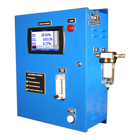
Super Systems MGA 6010 Operation manual

Thermo Scientific
Thermo Scientific Orion Versa Star user manual

Johnson
Johnson 40-6526 instruction manual
