Shimmer Shimmer3 User manual

Copyright © Shimmer Research 2013
Realtime Technologies Ltd IMU User Manual
All rights reserved Rev 1.1
1
EMG User Guide
Revision 1.12

Copyright © Shimmer 2017
Realtime Technologies Ltd EMG User Guide
All rights reserved Rev 1.12
2
Legal Notices and Disclaimer
Redistribution IS permitted provided that the following conditions are met:
Redistributions must retain the copyright notice, and the following disclaimer. Redistributions in electronic form must reproduce the above
copyright notice, this list of conditions and the following disclaimer in the documentation and/or other materials provided with the
document.
Neither the name of Shimmer Research, or Realtime Technologies Ltd. nor the names of its contributors may be used to endorse or promote
products derived from this document without specific prior written permission.
THIS DOCUMENT IS PROVIDED BY THE COPYRIGHT HOLDERS AND CONTRIBUTORS "AS IS" AND ANY EXPRESS OR IMPLIED WARRANTIES,
INCLUDING, BUT NOT LIMITED TO, THE IMPLIED WARRANTIES OF MERCHANTABILITY AND FITNESS FOR A PARTICULAR PURPOSE ARE
DISCLAIMED. IN NO EVENT SHALL THE COPYRIGHT OWNER OR CONTRIBUTORS BE LIABLE FOR ANY DIRECT, INDIRECT, INCIDENTAL,
SPECIAL, EXEMPLARY, OR CONSEQUENTIAL DAMAGES (INCLUDING, BUT NOT LIMITED TO, PROCUREMENT OF SUBSTITUTE GOODS OR
SERVICES; LOSS OF USE, DATA, OR PROFITS; OR BUSINESS INTERRUPTION) HOWEVER CAUSED AND ON ANY THEORY OF LIABILITY,
WHETHER IN CONTRACT, STRICT LIABILITY, OR TORT (INCLUDING NEGLIGENCE OR OTHERWISE) ARISING IN ANY WAY OUT OF THE USE
OF THIS DOCUMENT, EVEN IF ADVISED OF THE POSSIBILITY OF SUCH DAMAGE.

Copyright © Shimmer 2017
Realtime Technologies Ltd EMG User Guide
All rights reserved Rev 1.12
3
Table of Contents
1. Introduction.............................................................................................................................. 5
2. General Information ................................................................................................................. 6
2.1. Safety Information ............................................................................................................. 6
2.2. Pre-Requisites.................................................................................................................... 6
2.3. EMG Unit Specification Overview....................................................................................... 6
3. Using the EMG Unit................................................................................................................... 7
3.1. Basic System Overview....................................................................................................... 7
Common Mode Rejection .......................................................................................................... 8
3.2. EMG Electrode Positioning................................................................................................. 8
3.3. Configuration Options and Recommended Settings............................................................ 9
Data Rate................................................................................................................................. 10
Gain......................................................................................................................................... 10
Input Multiplexer..................................................................................................................... 11
Right-Leg Drive (Common-mode Rejection) ............................................................................. 11
Test Signal ............................................................................................................................... 12
4. Measuring EMG Signals........................................................................................................... 13
4.1. Best Practice on How to Acquire an EMG signal................................................................ 13
Skin Preparation ...................................................................................................................... 13
Research.................................................................................................................................. 13
Sampling Frequency................................................................................................................. 13
4.2. Signal Calibration ............................................................................................................. 13
ADC Offset Measurement........................................................................................................ 14
Gain Measurement.................................................................................................................. 14
5. Common EMG Signal Processing Techniques .......................................................................... 15
5.1. Filtering [2] ...................................................................................................................... 15
5.2. Extracting the Linear Envelope of an EMG Signal [3]......................................................... 16
5.3. Integration Techniques [3] ............................................................................................... 17
5.4. Normalisation [3, 4] ......................................................................................................... 18
5.5. Frequency Domain Analysis [3, 5]..................................................................................... 18
6. Hardware Considerations........................................................................................................ 19

Copyright © Shimmer 2017
Realtime Technologies Ltd EMG User Guide
All rights reserved Rev 1.12
4
6.1. Board Layout.................................................................................................................... 19
6.2. Channel assignment......................................................................................................... 20
6.3. Data considerations ......................................................................................................... 21
7. Firmware Considerations ........................................................................................................ 21
8. Troubleshooting...................................................................................................................... 21
8.1. Verifying That Your EMG Unit Works................................................................................ 21
8.2. Signal Quality ................................................................................................................... 21
9. References .............................................................................................................................. 22
10. Appendices.......................................................................................................................... 23
10.1. Legacy Hardware.......................................................................................................... 23
Board Layout ........................................................................................................................... 23
Channel assignment................................................................................................................. 24
Troubleshooting ...................................................................................................................... 25
10.2. Opening the Shimmer3 expansion enclosure................................................................ 25

Copyright © Shimmer 2017
Realtime Technologies Ltd EMG User Guide
All rights reserved Rev 1.12
5
1. Introduction
This document is an accompaniment to the Shimmer3 EMG Unit (called EMG Unit in the rest of this
document). Its purpose is to aid the user in getting started with EMG measurements.
The EMG Unit can be configured to measure electrical signals from the skin, including EMG
(Electromyograph). Any user who wishes to use Shimmer hardware to record ECG
(Electrocardiograph) signals from the skin should refer to the Shimmer3 ECG User Guide, which is
available for download from http://www.shimmersensing.com.
The five-wire EMG Unit can be configured to record the electrical activity associated with skeletal
muscle contractions; this can be used to analyze and measure the biomechanics of human or animal
movement. The EMG Unit is non-invasive, measuring surface EMG and, therefore, the activity it
measures is a representation of the activity of the whole muscle or group of muscles whose
electrical activity is detectable at the electrode site. The EMG Unit offers a wireless solution for a
host of muscle, gait and posture disturbances in an easy to integrate and ergonomically valuable
arrangement. Signals are collected from the skin via five wires, which are connected externally to
the Shimmer3 EMG Unit, and to which should be attached conventional disposable electrodes. The
EMG Unit uses a low-power, multichannel analog front-end especially designed for biopotential
measurements, consisting of delta-sigma analog-to-digital converters and programmable gain
amplifiers.

Copyright © Shimmer 2017
Realtime Technologies Ltd EMG User Guide
All rights reserved Rev 1.12
6
2. General Information
2.1. Safety Information
As a precaution it is important to note that the EMG leads are not to be applied to the subject's body
while unit is in a USB dock or multi-charger.
2.2. Pre-Requisites
A Shimmer3 EMG Unit programmed with appropriate firmware. For example, LogAndStream
(v0.6.0 or greater) can be used to stream data over Bluetooth and/or log data to the SD card
or SDLog (v0.12.0 or greater) can be used to log data to the SD card; both are available for
download from www.shimmersensing.com.
Five DIN snap leads.
-9-inch and 18-inch leads are shipped with the EMG Development Kit and EMG
Bundles.
-Replacements can be purchased from www.shimmersensing.com.
Surface EMG electrodes.
-Disposable electrodes are shipped with the EMG Development Kit and EMG Bundles.
-For replacements, see www.shimmersensing.com. Alternatively, the Covidien
Kendall Disposable Surface EMG/ECG/EKG electrodes 1" (24mm) or Covidien Kendall
Disposable Surface EMG/ECG/EKG electrodes 1 3/8" (35mm), available on www.bio-
medical.com with product codes 'BRD H124SG' and 'BRD H135SG', respectively, and
the Ambu Blue Sensor T electrodes, available from various suppliers, are all suitable
options and have been validated for use with Shimmer equipment.
2.3. EMG Unit Specification Overview
For specifications on the general Shimmer3 part, (i.e. microprocessor, radio, data storage
and inertial sensors) of the Shimmer3 EMG Unit, please refer to the Shimmer User Manual.
Gain: Configurable (1, 2, 3, 4, 6, 8, 12).
Data rate: software configurable (125, 250, 500, 1000, 2000, 4000, 8000 SPS).Input
differential dynamic range
1
: approx 800 mV (for gain = 6).
Bandwidth
2
: 8.4 kHz
Ground: Wilson Type Driven Ground
Input Protection: ESD and RF/EMI filtering; Current limiting; inputs include defibrillation
protection (survive only, not repeat). NOTE: For inputs Ch1N and Ch1P the defibrillation
protection is not present to facilitate Respiration demodulation when the EMG Unit is
configured as ECG Unit, refer to Shimmer3 ECG Unit for details.
Connections: Input Ch1N, Input Ch1P, Input Ch2N, Input Ch2P, Reference (Ref).
oAll Hospital-Grade 1mm Touchproof IEC/EN 60601-1 DIN42-802 jacks.
1
Calculated specification; exact value subject to environmental and component variation. ADS1292R is
optimized for power with a differential input signal of approx. 300 mV when gain = 6.
2
Specifications from ADS1292R datasheet; exact value subject to environmental and component variation.
Copyright © Shimmer 2017
Realtime Technologies Ltd EMG User Guide
All rights reserved Rev 1.12
7
Ultra-lightweight (31 grams); Compact Dimensions (65 x 32 x 12 mm).
EEPROM memory: 2048 bytes.
3. Using the EMG Unit
3.1. Basic System Overview
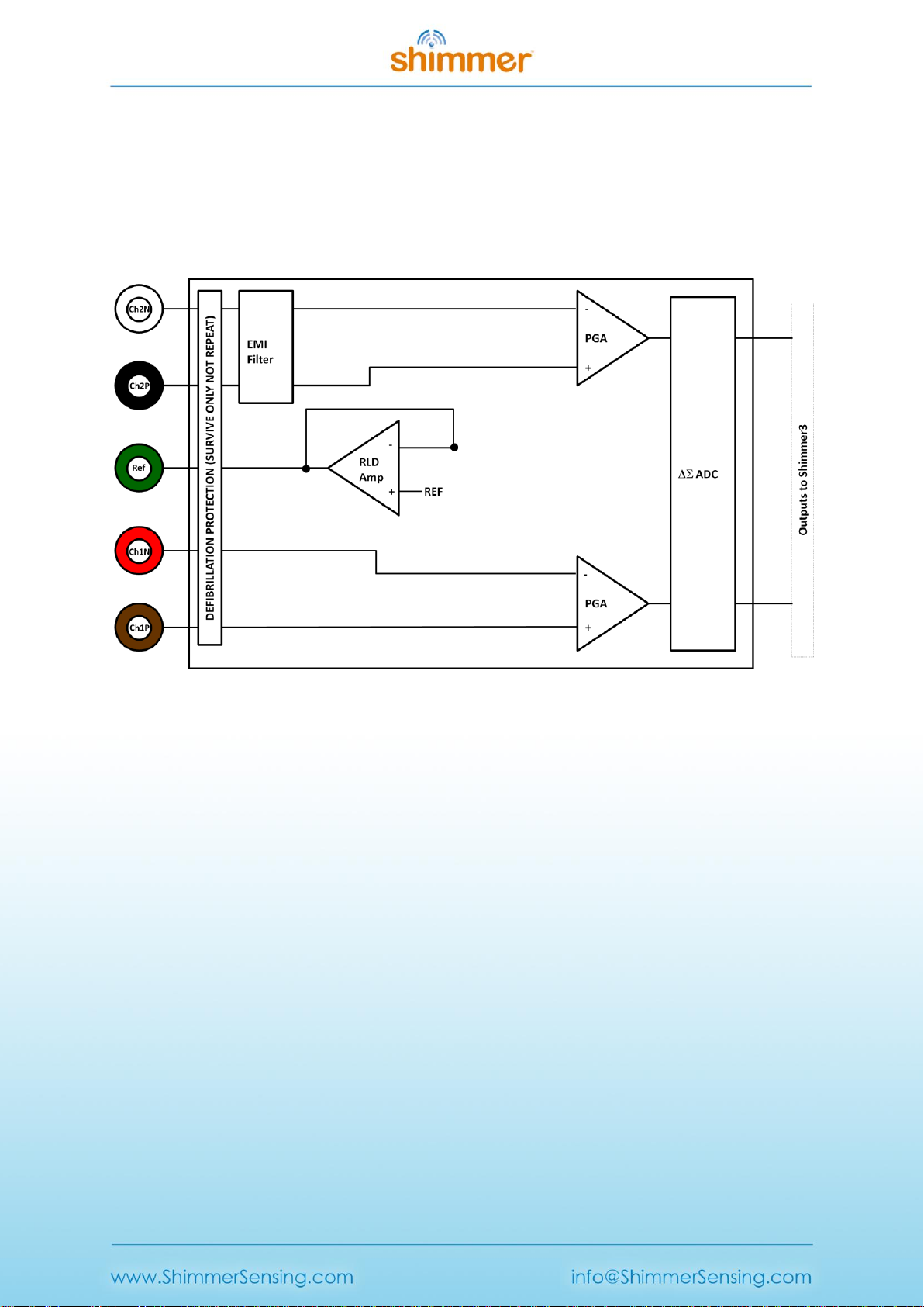
Figure 3-1: Simplified Block Diagram
Electrodes: Each EMG board connects to Ch2N (white), Ch2P (black), Ref (green), Ch1N (red)
and Ch1P (brown) electrodes.
Defibrillation protection: Survive only; not repeat. No defibrillation protection is present for
inputs Ch2P and Ch2N to facilitate Respiration demodulation (refer to Shimmer3 ECG User
Guide).
EMI Filter: Reduces electromagnetic interference; -3dB filter bandwidth is approximately
3MHz.
Right-Leg Drive Amplifier (RLD Amp): Counteracts common-mode interference (e.g. from
mains power lines, fluorescent lights and other sources).
Programmable Gain Amplifier (PGA): Increases amplitude of input signal; seven gain
settings available. See Section 4.2 to accurately calculate the gain of your device. Default
gain is configurable in software.
Analog to Digital Converters ( ADC): Converts the input analogue signals to a digital
representation of this signal by a 24-bit signed integer value to each sample. These values
are fed to the Shimmer3 processor to be saved to the SD card or transmitted over Bluetooth.

Copyright © Shimmer 2017
Realtime Technologies Ltd EMG User Guide
All rights reserved Rev 1.12
8
Common Mode Rejection
Each EMG board connects to five electrodes, namely, a positive and a negative electrode for each for
two channels and a neutral reference electrode. The reason for using three electrodes in this way is
that the EMG signal amplitude is, typically, very small relative to noise, for example, interference
from power lines and nearby electrical sources. The signal picked up by each individual electrode
consists of noise from the environment along with the local electrical signal from the muscles at the
position of skin contact. The noise from the environment is common to all electrodes, whilst the
local electrical signal depends on the electrode’s position. Thus, if one signal is subtracted from
another, the common component (the undesired noise) will be cancelled by the subtraction, whilst
the local signals (the desired EMG component) will remain after subtraction and can be amplified to
make it easier to process. This process is called Common Mode Rejection (CMR) and is used in the
Shimmer EMG board.
3.2. EMG Electrode Positioning
The inputs to the EMG Unit are labelled according to the suggested placement, in order to measure
EMG data from two channels:
Channel 1:
oCh1N Negative terminal
oCh1P Positive Terminal
Channel 2:
oCh2N Negative terminal
oCh2P Positive Terminal
Reference electrode:
oRef
Figure 3-2: Example positioning of the electrodes for EMG measurement.

Copyright © Shimmer 2017
Realtime Technologies Ltd EMG User Guide
All rights reserved Rev 1.12
9
Figure 3-2 shows an example of how the electrodes should be positioned on the body. The positive
and negative electrodes should be placed in parallel with the muscle fibres of the muscle being
measured, near the centre of the muscle. The reference electrode should be placed at an electrically
neutral point of the body, as far away as reasonably possible from the muscle being measured. Bony
prominences such as those at the ankle and the wrist are recommended.
The following recommendations should also be noted:
The electrode material should be Ag/AgCl and the ideal centre to centre inter-electrode
distance for the positive and negative electrodes is 20mm. The electrode size should not
exceed 10mm.
The electrodes must NOT be placed on the tendon of the muscle. As muscles reach their
tendon point the fibres become thinner and produce an EMG signal with decreased
amplitude.
The electrodes must NOT be placed on the motor point of the muscle. This gives inaccurate
data as the signal produced is a summation of both nervous and muscular activity and as
such does not just represent the activity of the muscle.
The electrodes must NOT be placed on the outside edges of the muscle. This increases the
chance of picking up crosstalk signals from other muscles which are not being measured.
3.3. Configuration Options and Recommended Settings
The EMG Unit contains two ADS1292R chips from Texas Instruments; these have a very wide and
varied range of available configuration options. These chips are referred to as "Chip1" and "Chip2"
throughout this document. This section aims to provide recommended settings, which will suit the
needs of most EMG measurement applications. The experienced user who wishes to have full
control over all of the configuration settings should refer to the ADS1292R datasheet from Texas
Instruments for more details.
There are two ADS1292R chips on the EMG Unit and each of these chips has eleven bytes of
configurable register settings. Ten of these configurable bytes are listed in Table 3-1 and their
recommended values are discussed in this section. The final byte, which pertains to GPIO settings, is
dealt with in firmware and not discussed here. Users should note that, for EMG measurement, only
one of the ADS1292R chips (referred to as "Chip1") should be active.
Byte
Name
Bit 7
Bit 6
Bit 5
Bit 4
Bit 3
Bit 2
Bit 1
Bit 0
0
CONFIG1:
Configuration Register 1
0
0
0
0
0
Data Rate
(DR2, DR1, DR0)
1
CONFIG2:
Configuration Register 2
1
0
1
0
X 3
0
INT_T
EST
TEST_F
REQ
2
LOFF:
Lead-Off Control Register
0
0
0
1
0
0
0
0
3
CH1SET:
Channel 1 Settings
0
Gain1
(G1_2, G1_1, G1_0)
MUX1
(M1_3, M1_2, M1_1, M1_0)
3
The Bit 3 in CONFIG2 denotes “X=0” for SR47-1 revision, and “X=1” for SR47-4 and greater revisions. This
feature has been configured automatically in both LogAndStream 0.11.0 and SDLog_v0.19.0 (and newer).

Copyright © Shimmer 2017
Realtime Technologies Ltd EMG User Guide
All rights reserved Rev 1.12
10
4
CH2SET:
Channel 2 Settings
0
Gain2
(G2_2, G2_1, G2_0)
MUX2
(M2_3, M2_2, M2_1, M2_0)
5
RLD_SENS:
Right Leg Drive Sense Selection
0
0
PDB_RL
D
RLD_LO
FF_SENS
RLD Settings
(RLD2N, RLD2P, RLD1N, RLD1P)
6
LOFF_SENS:
Lead-Off Sense Selection
0
0
0
0
0
0
0
0
7
LOFF_STAT:
Lead-Off Status Selection
0
0
0
0
0
0
0
0
8
RESP1:
Respiration Control Register 1
0
0
0
0
0
0
1
0
9
RESP2:
Respiration Control Register 2
0
0
0
0
0
0
RLDRE
F_INT
1
Table 3-1 ADS1292R configuration register bytes - recommended values
Table 3-1 lists the recommended values of the ADS1292R configuration register bytes. The values of
the individual bits are listed in the columns labelled Bit 7 (MSB), Bit 6, and so on to Bit 0 (LSB). The
recommended values of some sets of bits, like multiplexer (MUX) settings, channel gain settings and
others, differ depending on the type of signal being measured (e.g. ECG or EMG), and others, like
output data rate and test signal, depend on the user's preferences.
Data Rate
The Data Rate for each chip can be set by modifying the three LSBs of the CONFIG1 register (Byte 0).
Table 3-2 lists the valid options and their corresponding data rate value in units of samples per
second (SPS). For EMG, a data rate of 500 SPS or more is recommended, although the needs of a
given application may vary.
Data Rate (SPS)
DR2
DR1
DR0
125
0
0
0
250
0
0
1
500 (recommended)
0
1
0
1000
0
1
1
2000
1
0
0
4000
1
0
1
8000
1
1
0
DO NOT USE
1
1
1
Table 3-2 EMG Data Rate options
Gain
The Gain setting can be configured independently for each of the two data channels on each chip by
modifying bits 4 - 6 of the CH1SET byte for channel 1 and of the CH2SET byte for channel 2,
respectively. The gain bits for channel 1 of a given chip are listed as G1_2 (MSB), G1_1 and G1_0
(LSB) in Table 3-1, whilst the equivalent for channel2 of the chip are listed as G2_2, G2_1 and G2_0,
respectively. These are collectively referred to as Gx_2, Gx_1 and Gx_0, respectively, in Table 3-3,
which lists the valid options and the corresponding gain value for each. For EMG, a gain value of 12 is
recommended.
Gain
Gx_2
Gx_1
Gx_0
6 (default)
0
0
0

Copyright © Shimmer 2017
Realtime Technologies Ltd EMG User Guide
All rights reserved Rev 1.12
11
1
0
0
1
2
0
1
0
3
0
1
1
4
1
0
0
8
1
0
1
12 (recommended)
1
1
0
DO NOT USE
1
1
1
Table 3-3 EMG Channel Gain options
Input Multiplexer
The multiplexer (MUX) settings can be configured independently for each of the two data channels
on each chip; the MUX bits for channel 1 of a given chip are listed as MUX1_3 (MSB), MUX1_2,
MUX1_1 and MUX1_0 (LSB) in Table 3-1, whilst the equivalent for channel2 of the chip are listed as
MUX2_3, MUX2_2, MUX2_1 and MUX2_0, respectively. Table 3-4 lists the recommended MUX
configuration for each chip and channel for EMG data collection.
Chip
MUX1_3
MUX1_2
MUX1_1
MUX1_0
MUX2_3
MUX2_2
MUX2_1
MUX2_0
Chip1
1
0
0
1
0
0
0
0
Chip24
0
0
0
1
0
0
0
1
Table 3-4 Recommended MUX settings for EMG
Right-Leg Drive (Common-mode Rejection)
The right-leg drive (RLD) settings determine the voltage that should be used at the input of the right-
leg drive amplifier for common-mode interference rejection and can be configured independently
for each chip. The RLD Settings bits for a given chip are listed as RLD2N, RLD2P, RLD1N and RLD1P in
Table 3-1. For EMG configuration, the recommended setting is to choose the inverted RLD signal
(RLDINV), provided by circuit elements outside of the chip to close the negative feedback loop on
Chip1 and no RLD signal on Chip2. This can be achieved by setting the configuration listed in Table
3-5.
Chip
RLD2N
RLD2P
RLD1N
RLD1P
Chip1
0
0
0
0
Chip2
0
0
0
0
Table 3-5 Recommended RLD channel selection settings for EMG
The PDB_RLD bit of the RLD_SENS byte (byte 5, bit 5) determines if the RLD buffer is powered on (1)
or not (0).
The RLD_LOFF_SENS bit of the RLD_SENS byte (byte5, bit 4) determines if the lead-off sense function
is enabled (1) or disabled (0).
4
Recall that Chip2 will not be enabled for EMG data collection; the MUX settings listed are recommended for
channel power down mode in the ADS1292R datasheet. For channel power down mode, bit7 of the CH1SET
and/or CH2SET bytes should be set to 1. Please refer to the ADS1292R datasheet for more information.

Copyright © Shimmer 2017
Realtime Technologies Ltd EMG User Guide
All rights reserved Rev 1.12
12
The RLDREF_INT bit of the RESP2 byte (byte 9, bit 1) controls the RLDREF signal source for the RLD
amplifier. If the value of the bit is 0, the reference signal is fed externally. If the value of the bit is 1,
an internally generated reference signal is generated.
For EMG data collection, the settings in Table 3-6 are recommended for PDB_RLD, RLD_LOFF_SENS
and RLDREF_INT.
Chip
PDB_RLD
RLD_LOFF_SENS
RLDREF_INT
Chip1
1
0
1
Chip2
0
0
0
Table 3-6 Recommended RLD settings for EMG
Test Signal
In order to test the EMG output channels, a test signal can be internally generated by each chip. This
signal can either be a DC voltage or a 1Hz square wave. To enable the test signal, the two LSBs of the
CONFIG2 byte (byte 1, bits 1-0) for each chip should be set as in Table 3-7. Furthermore, the MUX1
or MUX2 bits should be set to 0000 so that the test signal will appear on channel 1 or channel 2,
respectively.
Test signal
INT_TEST
TEST_FREQ
DC test signal
1
0
1 Hz square wave test signal
1
1
No test signal
0
0
Table 3-7 Test signal settings for EMG

Copyright © Shimmer 2017
Realtime Technologies Ltd EMG User Guide
All rights reserved Rev 1.12
13
4. Measuring EMG Signals
4.1. Best Practice on How to Acquire an EMG signal
Skin Preparation
A good electrode to skin contact is essential for accurate surface EMG readings. The skin should be
cleaned with alcohol or sanitizer to remove any inhibitory particles. If hairs are obstructing the
contact they should be shaved for the best readings.
Research
It is good practice to research the anatomy of each muscle you wish to measure. An understanding
of each muscle’s shape, fibre directionality, motor points, tendon positions and insertion points will
help you to prepare a high quality EMG reading.
Sampling Frequency
Although the sampling frequency is entirely up to the user, it should be noted that the surface EMG
spectrum is 20Hz-400Hz however the majority of the signal lies in the 20Hz-250Hz spectrum.
Therefore for many applications a sampling rate of 512Hz will ensure high quality reproducibility of
the actual summation of the muscle’s activity however a higher sampling rate may be required for
certain applications.
4.2. Signal Calibration
The ADC output for each channel from the EMG Unit has a signed 24bit digital format. The
relationship between the ADC output and the EMG Signal in mVolts is given by the formula:
Equation 1
In order to convert the ADC output signal to mVolts which is the standard unit for an EMG signal,
the above formula can be rearranged as follows:
, Equation 2
where
. Equation 3
Considering that the ADC sensitivity is known and that the ADC Output is measured from the
Shimmer, in order to calculate the EMG signal in mVolts, the values for the Gain and ADC Offset
must simply be inserted into Equation 2.
The nominal value for the ADC offset of the EMG Unit data channels is 0 and the gain is software
configurable (see Section 3.3). For most applications these values are sufficiently accurate. If
improved accuracy is required for a given application, then the gain and ADC Offset of each of the
EMG Unit channels can be measured.

Copyright © Shimmer 2017
Realtime Technologies Ltd EMG User Guide
All rights reserved Rev 1.12
14
ADC Offset Measurement
To determine the offset of each channel, the relevant inputs for that channel should be connected to
each other. For example to determine the Channel 1 offset, the Ch1P and Ch1N inputs should be
connected to each other. The ADC offset for the Channel 1 is then calculated as the mean ADC
output on the EMG Ch1 of the Shimmer with the Ch1P and Ch1N inputs connected together. This
can easily be found by saving uncalibrated data to a file and then calculating the mean value. The
offset for other channels is calculated similarly.
Gain Measurement
In order to determine the gain for the EMG sensor channels, a sine wave signal from a signal
generator should be applied to the sensor electrodes. The channels should be calibrated separately,
with the sine wave signal applied to the appropriate pair of electrodes in each case. It is
recommended to use a signal with amplitude ±1 mV approx (2 mV peak-to-peak) and frequency
between 0.05Hz and 159Hz. The gain for each channel may differ.
The gain for each channel is calculated as follows
Equation 4
where the ADC Offset and ADC Sensitivity are as defined previously, Max ADC Output is the
maximum value of the uncalibrated data on the channel of interest and Max Input Signal in mVolts is
the half wave amplitude of the input sine-wave signal (e.g. 1mV when using a signal of ±1 mV).

Copyright © Shimmer 2017
Realtime Technologies Ltd EMG User Guide
All rights reserved Rev 1.12
15
5. Common EMG Signal Processing Techniques
The type of EMG signal processing a user will require is entirely dependent on the specific
requirements of their application. The techniques outlined below are intended to aid the user in
getting started with investigating the specific type of EMG signal processing they require and to
provide them with information on common methodologies which can improve signal quality. For a
more in depth overview of EMG signal processing techniques it is recommended to consult
literature, such as that authored by Raez et al. [1]. Each section below features examples of
appropriate literature on the subject matter to aid the user with some of the types of signal
processing they may require.
Please note that software solutions for EMG signal processing are not currently provided by
Shimmer and the information below is intended as a starting point for the new user to aid their
software development. Should you require customised software solution, please contact the
Shimmer team.
5.1. Filtering [2]
In order to remove signal interference from mains electricity, notch filtering is recommended. To do
this a band-stop filter should be adjusted to block the local mains frequency. Eliminate the 50Hz
frequency in most parts of the world or 60Hz frequency in the Americas. The APIs and Instrument
Drivers, provided by Shimmer for development of software in Java/Android, LabVIEW, Matlab and
C#, include the implementation of optional mains filtering in the example code.
Note: Notch filtering of an EMG signal is not recommended if the filter cut-off frequency lies within
the bandwidth of interest as it will remove EMG signal of interest along with the noise. In such cases
it is recommended to take measures to reduce the levels of noise at the noise source.
The ADS1292R chips on the EMG Unit provide a DC-coupled measurement. Therefore, high pass
filtering with a cut-off frequency of 5Hz or greater is highly recommended.
A band-pass filter can be useful for the elimination of low frequency noise such as motion artifact as
well as high frequency noise sources which are outside the bandwidth of interest. Typically, a filter
with a lower cut-off frequency (Fc,low) of 20Hz and a higher cut-off frequency (Fc,high) of 400-800Hz
(depending on the user’s range of interest) is used.
Care should be taken in the design of filters and it should be remembered that the filters may
impose the requirement for a settling time after data collection starts. The APIs and Instrument
Drivers, provided by Shimmer for development of software in Java/Android, LabVIEW, Matlab and
C#, include the implementation of optional high and low pass filtering in the example code.
Figure 5-1 below shows an EMG signal with and without filtering. The top signal (blue) is a noisy
calibrated EMG signal with no filtering applied. The signal was captured from the calf muscle using
Multi Shimmer Sync for Windows software, at a sampling frequency of 1024 Hz.

Copyright © Shimmer 2017
Realtime Technologies Ltd EMG User Guide
All rights reserved Rev 1.12
16
The middle signal (orange) is the same signal with a Butterworth band-pass filter applied, with
Fc,low set to 20Hz and Fc,high set to 511Hz. It can be observed that the motion artifact has been
removed.
The bottom signal (also blue) is the band-passed signal with a notch filter applied (Fc = 50Hz,
bandwidth (BW) = 1Hz). It can be observed that a substantial level of noise has been removed and
the EMG signal remains.
Figure 5-1: Bandpass Filtering and Notch Filtering of Calibrated EMG Data
5.2. Extracting the Linear Envelope of an EMG Signal [3]
The linear envelope of an EMG signal is an easy-to-interpret representation of the raw signal. Among
other uses, it is used to detect when a muscle is active and to give an indication of the overall level
of activity in a particular muscle at any time.
There are a variety of methods to extract the linear envelope of an EMG signal. The most commonly
used is to firstly apply full wave rectification to the signal and to subsequently pass it through a low
pass filter (Fc = 1-10Hz). The effects of lowering the cut-off frequency of the filter are that the
resulting signal will have smoother, rounded edges but will contain less information from the original
EMG signal.
Alternatively, averaging techniques on a moving window of samples can be used: calculating the
root mean square or mean of the moving window of values are the most commonly used methods.
Increasing the number of samples in the moving window will produce a linear envelope with
smoother, rounded edges but will reduce the amount of information contained in the processed
signal. Figure 5-2 below shows the linear envelope of a raw EMG signal with a moving window
selected at 100ms.
Copyright © Shimmer 2017
Realtime Technologies Ltd EMG User Guide
All rights reserved Rev 1.12
17
Figure 5-2: A raw EMG signal and its linear envelope.
5.3. Integration Techniques [3]
Continuous integration is the integration of the current sample with all previous samples in the
signal. It is commonly used to represent total energy expenditure in the associated muscle.
Periodic reset integration is similar to continuous integration except that, after a defined period, the
integral value is reset to 0 and the integration process begins again. It is commonly used to compare
the energy output of a muscle over a number of pre-defined periods.
Threshold reset integration is also similar to continuous integration except that when the integral
value reaches a predefined threshold the integral value is reset to 0 and the integration process
begins again. It is commonly used to monitor how long it takes for a muscle to expend a pre-defined
amount of energy.
Figure 5-3 below shows graphs of a signal with the application of continuous integration (top, blue),
periodic reset integration with a period of 100ms (middle, orange) and threshold reset integration
with a threshold of 0.8mV (bottom, blue).

Copyright © Shimmer 2017
Realtime Technologies Ltd EMG User Guide
All rights reserved Rev 1.12
18
Figure 5-3: Continuous integration, periodic reset integration and threshold reset integration
5.4. Normalisation [3, 4]
Normalisation is used to eliminate variability across subjects, electrode placement and day to day
differences in measures of the same muscle site, when carrying out research using EMG. Maximum
voluntary contractions compared to strain gauge data are often used to associate electrical muscular
activity with strength and subsequently compare the EMG readings from a variety of subjects.
5.5. Frequency Domain Analysis [3, 5]
Analysis of the EMG signal in the frequency domain allows the user to extract information about
which particular type of muscle cells are firing at any one instance. In simplified terms; Type ll, fast
twitch cells cause the higher frequency components of the signal and Type l, slow twitch cells cause
the lower frequency portion of an EMG signal.
As a muscle fatigues it becomes more reliant on Type l cells. Using this fact and monitoring the
median frequency of an EMG signal allows the user to monitor muscular fatigue (It is important to
note that the amplitude of an EMG signal/linear-envelope does not necessarily reduce as a muscle
fatigues, therefore frequency analysis is the only method for monitoring muscle fatigue with EMG).
Frequency analysis of an EMG signal is one of the most complex signal processing techniques to
implement and analyse. As such an in depth literature review of the topic should be conducted
before utilising the associated techniques.
Copyright © Shimmer 2017
Realtime Technologies Ltd EMG User Guide
All rights reserved Rev 1.12
19
6. Hardware Considerations
6.1. Board Layout
Note: For Shimmer3 EMG hardware purchased prior to July 2015, please refer to Appendix 10.2 of
this document.
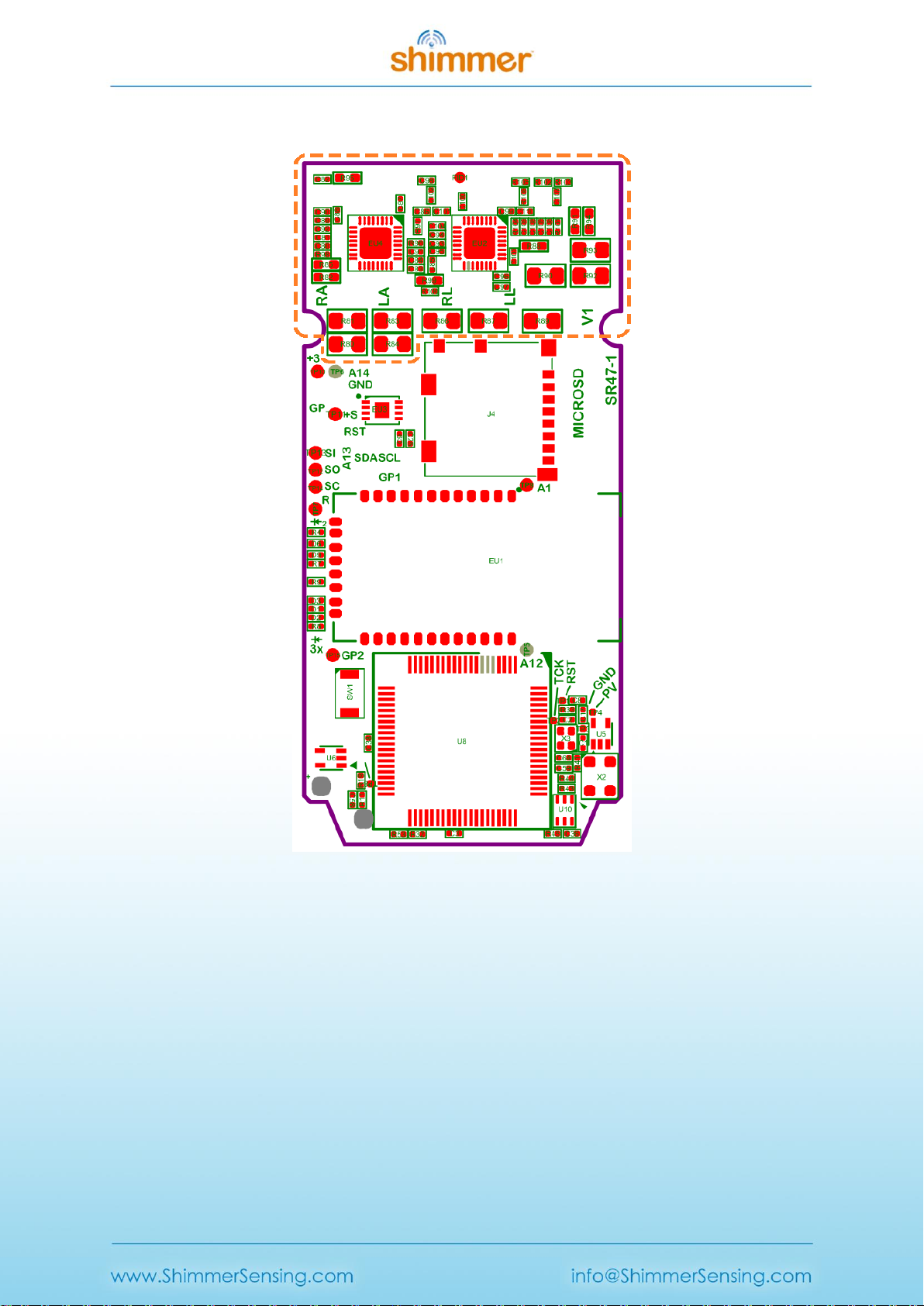
Figure 6-1 and Figure 6-2 show the board layout for the EMG Unit, with components labelled. The
two ADS1292R chips are labelled EU1 and EU2 and are referred to in the documentation as Chip1
and Chip2, respectively. The area on the board within with the orange dashed lines is the part of the
circuitry of the EMG Unit that is described in this User Guide. The area on the board outside of the
orange dashed lines is the circuitry of the Shimmer3, described in the Shimmer User Manual.
Figure 6-1: EMG Board Layout (bottom view)
Copyright © Shimmer 2017
Realtime Technologies Ltd EMG User Guide
All rights reserved Rev 1.12
20
Figure 6-2: EMG Board Layout (top view)
6.2. Channel assignment
When the MUX settings recommended in Section 3.3 of this document are configured, the channel
assignment for EMG is as follows:
Chip1 Channel 1: J15 (Brown) - J14 (Red).
Chip1 Channel 2: J12 (Black) - J10 (White).
Reference: J13 (Green).
Chip2: not active for EMG configuration.
Other manuals for Shimmer3
2
Table of contents
Other Shimmer Accessories manuals


