Shimmer External Expansion Board User manual

Copyright © Shimmer Research 2013
Realtime Technologies Ltd IMU User Manual
All rights reserved Rev 1.1
1
External Expansion Board
User Guide
Revision 1.6

Copyright © Shimmer 2016
Realtime Technologies Ltd External Expansion Board User Guide
All rights reserved Rev 1.6
1
Legal Notices and Disclaimer
Redistribution IS permitted provided that the following conditions are met:
Redistributions must retain the copyright notice, and the following disclaimer. Redistributions in electronic form
must reproduce the above copyright notice, this list of conditions and the following disclaimer in the
documentation and/or other materials provided with the document.
Neither the name of Shimmer Research, or Realtime Technologies Ltd. nor the names of its contributors may
be used to endorse or promote products derived from this document without specific prior written permission.
THIS DOCUMENT IS PROVIDED BY THE COPYRIGHT HOLDERS AND CONTRIBUTORS "AS IS" AND
ANY EXPRESS OR IMPLIED WARRANTIES, INCLUDING, BUT NOT LIMITED TO, THE IMPLIED
WARRANTIES OF MERCHANTABILITY AND FITNESS FOR A PARTICULAR PURPOSE ARE DISCLAIMED.
IN NO EVENT SHALL THE COPYRIGHT OWNER OR CONTRIBUTORS BE LIABLE FOR ANY DIRECT,
INDIRECT, INCIDENTAL, SPECIAL, EXEMPLARY, OR CONSEQUENTIAL DAMAGES (INCLUDING, BUT
NOT LIMITED TO, PROCUREMENT OF SUBSTITUTE GOODS OR SERVICES; LOSS OF USE, DATA, OR
PROFITS; OR BUSINESS INTERRUPTION) HOWEVER CAUSED AND ON ANY THEORY OF LIABILITY,
WHETHER IN CONTRACT, STRICT LIABILITY, OR TORT (INCLUDING NEGLIGENCE OR OTHERWISE)
ARISING IN ANY WAY OUT OF THE USE OF THIS DOCUMENT, EVEN IF ADVISED OF THE
POSSIBILITY OF SUCH DAMAGE.

Copyright © Shimmer 2016
Realtime Technologies Ltd External Expansion Board User Guide
All rights reserved Rev 1.6
2
Table of Contents
Table of Contents......................................................................................................................... 2
1. Introduction ......................................................................................................................... 3
2. General Information ............................................................................................................. 4
2.1. Pre-Requisites .........................................................................................................................4
2.2. External Expansion Board Features ........................................................................................4
2.3. Wire Connections.................................................................................................................... 5
2.4. Test Pad Connections.............................................................................................................. 6
2.5. Board Layout ...........................................................................................................................7
3. Using the External Expansion Board (Typical Applications)..................................................... 8
3.1. Connecting an Analog Output Sensor..................................................................................... 8
3.2. Connecting a Digital Output Sensor using the SPI interface...................................................8
Note for Shimmer3 users................................................................................................................ 8
3.3. Connecting to a Serial UART ................................................................................................... 9
3.4. Connecting a Parallel Bus interface ........................................................................................ 9
3.5. Connecting an External Power Battery Pack........................................................................... 9
4. Firmware Considerations .................................................................................................... 10
4.1. +/-5V DC Regulator ...............................................................................................................10
4.2. User button ...........................................................................................................................10
4.3. Multifunction pins.................................................................................................................10

Copyright © Shimmer 2016
Realtime Technologies Ltd External Expansion Board User Guide
All rights reserved Rev 1.6
3
1. Introduction
This document is an accompaniment to the Shimmer External Expansion Board (formerly known as
the Shimmer AnEx Board). Its purpose is to be used in conjunction with the Shimmer External
Expansion Board Tutorial Video to aid the user in getting started with the External Expansion Board.
The External Expansion Board Board enables an Analog Output Sensor, a Digital Output Sensor, a
Serial UART or a Parallel Bus Interface to connect to Shimmer. The External Expansion Board is
connected to a Shimmer device via the external connector and is positioned outside the Shimmer
enclosure.
The External Expansion Board enables users to incorporate additional functionality to the Shimmer
providing an outlet to develop their specific application to their own user requirements. It allows
easy prototyping of 3rd part sensors or custom sensing solutions with Shimmer.

Copyright © Shimmer 2016
Realtime Technologies Ltd External Expansion Board User Guide
All rights reserved Rev 1.6
4
2. General Information
2.1. Pre-Requisites
A Shimmer 2, Shimmer 2r or Shimmer31device programmed with appropriate firmware.
For example, LogAndStream (BtStream for Shimmer2/2r) firmware can be used to stream
data over Bluetooth and/or log data to the SD card or SDLog firmware can be used to log
data to the SD card; both are available for download from www.shimmersensing.com and
the latest version should always be used.
An External Expansion Board.
2.2. External Expansion Board Features
Easy access to Shimmer microcontroller signals using wire hole or solder pads.
+/-5VDC charge pump regulator with software-controlled enable pin2.
Software assignable User Control button.
Connect an auxiliary power supply.
1Please refer to the later sections of this document for more details on using the Expansion Board with
Shimmer3.
2The 5V regulator is not compatible with Shimmer3.

Copyright © Shimmer 2016
Realtime Technologies Ltd External Expansion Board User Guide
All rights reserved Rev 1.6
5
2.3. Wire Connections
PCB Label
Connector Pin#
hardware.h Pin Label
Shimmer2/2r Function
CLK
4
UCLK0
SPI0 CLK, or GPIO
(wired to MicroSD)
SI
6
SIMO0
SPI0 SIMO or GPIO
(wired to MicroSD)
#RST
8
N/A
BSL programming, Power control and
Board Reset.
Same as Shimmer reset button.
RX
2
URXD0
UART0 RXD or GPIO
A level shifter is required to interface with
an RS-232 cable
CTS
16
SER0_CTS
SPI0 UART CTS or interruptible GPIO
+3
17
PV
3.0V regulated voltage.
Do not exceed 50mA when using this
connection.
+5
N/A
N/A
5.0V regulated voltage. Do not exceed
12mA when using this connection
-5
N/A
N/A
-5.0V regulated voltage. Do not exceed
12mA when using this connection
TX
3
UTXD0
UART0 TXD or GPIO.
A level shifter is required to interface with
an RS-232 cable
SO
5
SOMI0
SPI0 SOMI, or GPIO
(wired to MicroSD)
A7
13
ADC_7
Analog ADC input 7, DAC output or GPIO.
Also used for MicroSD Flash Dat1
G
GND
Ground Connection
A0
12
ADC_0
Analog ADC input 0 or GPIO. . Also used
for MicroSD Flash Dat2
Table 1 Wire Connections for Shimmer2/2r
PCB Label
Connector Pin#
MSP430 Pin / Label
Shimmer3 Function
RX
2
P3.5 / SA_SOMI_RXD
USART A0 SOMI or RXD or GPIO
A level shifter is required to interface with
an RS-232 cable
TX
3
P3.4 / SA_SIMO_TXD
USART A0 TXD or SIMO or GPIO.
A level shifter is required to interface with
an RS-232 cable
CLK
4
FLASH_SCLK_EXT
USART B1 SPI CLK, or GPIO
(wired to MicroSD)
SO
5
P5.4 / FLASH_SOMI
USART B1 SPI SOMI, or GPIO
(wired to MicroSD)
SI
6
P3.7 / FLASH_SIMO
USART B1 SPI SIMO or GPIO
(wired to MicroSD)
#RST
8
RST / MSP_RESET_N
Microcontroller Reset line - typically used
to reset the board
A0
12
P6.6 / ADC6_FLASHDAT2
Analog ADC input 6 or GPIO

Copyright © Shimmer 2016
Realtime Technologies Ltd External Expansion Board User Guide
All rights reserved Rev 1.6
6
(wired to MicroSD)
A7
13
P6.7 / ADC7_FLASHDAT1
Analog ADC input 7 or GPIO
(wired to MicroSD)
CTS
16
P7.7 / ADC_15_RADIO_DC
ADC Input 15 or GPIO
Alternate function is reserved for
coprocessor Spy-Bi-Wire
+3
17
PV
3.0V regulated voltage. Do not exceed
100mA when using this connection.
+5
N/A
N/A
5.0V regulated voltage. Do not exceed
12mA when using this connection. NOT
compatible with Shimmer3.
-5
N/A
N/A
-5.0V regulated voltage. Do not exceed
12mA when using this connection. NOT
compatible with Shimmer3.
G
GND
Ground Connection
Table 2 Wire Connections for Shimmer3
2.4. Test Pad Connections
PCB PAD
Location
Connector Pin#
(name)
hardware.h Pin Label
Function
Center above
Shimmer
Connector
14 (BSL_TX)
PROG_OUT
Programming pin or interruptible GPIO
Right of
Center below
Shimmer
Connector
11 (BSL_RX)
PROG_IN
Programming pin. Do not use this pin for
GPIO.
Left of Center
below
Shimmer
Connector
9 (PV_REG)
N/A
Board pre-regulator voltage after isolation
diode.
When used as an output, this will be the
battery voltage. Typically 2.8-3.7V. Do not
exceed 200mA when using this
connection.
A DC power source (bench or battery) can
be connected to this connection. To
prevent damage to the power source a
series diode is recommended when the
Shimmer battery is also in use and the
power supply is <4.0VDC. Do not exceed
5.5V or 200mA.
Table 3 Test Pad Connections for Shimmer2/2r

Copyright © Shimmer 2016
Realtime Technologies Ltd External Expansion Board User Guide
All rights reserved Rev 1.6
7
2.5. Board Layout
Figure 1: External Expansion Board Top View
Figure 2: External Expansion Board Bottom View

Copyright © Shimmer 2016
Realtime Technologies Ltd External Expansion Board User Guide
All rights reserved Rev 1.6
8
3. Using the External Expansion Board (Typical Applications)
3.1. Connecting an Analog Output Sensor
Using the sensor specification, chose either +3, +5, or +/-5V3as the power supply connections to the
sensor (in order of preference). The output of the sensor should be tied to either the A0 or A7 ADC
inputs4. If the output is outside of the range of the Shimmer ADC (3V max) an attenuator must be
added.
Note: For Shimmer2/2r there is an issue with crosstalk on the accelerometer signals when the ADC is
provided with an un-buffered moderate to high impedance signal. To avoid such issues signals
should be buffered with an appropriate voltage buffer.
If the sensor uses the bipolar power supply, the output must be AC-coupled via a series capacitor to
an appropriate DC bias resistor network connected to the ADC input pin.
Example: A sensor requires +/-5V supply, and has a output of +/- 1.25V. A 10µF capacitor is used to
couple a signal such that 1.5V = zero-signal by connecting a 100k resistor from A0 (ADC0) to +3
(3.0V) and a 100k resistor from A0 (ADC0) to G (GND).
Any remaining GPIO pins can be used to configure control pins on the sensor. Verify the
configuration of any of these pins in the Shimmer application code.
3.2. Connecting a Digital Output Sensor using the SPI interface
Paying attention to the required master-slave relationship in your application (Shimmer is usually
master), connect up the SI,SO, and CLK pins. Use another GPIO pin as a Chip Select to complete the
digital interface. The UART0 module will need to be configured for SPI mode-- there are examples for
Shimmer2/2r in the TinyOS reference code library. For power supply connections chose either +3,
+5, or +/-5V as the power supply connections to the sensor (in order of preference).
Remember that the Shimmer's microSD storage is also connected to the SPI bus. An internal
expansion board may also use this signal. The application must ensure that the bus is correctly
multiplexed using the SPI0 chip-select signals.
Any remaining GPIO pins can be used to configure control pins on the sensor. Verify the
configuration of any of these pins in the Shimmer application code.
Note for Shimmer3 users
When using the External Expansion Board with Shimmer3, the SPI bus is shared with the microSD,
making the interface much more complicated than that for the PROTO3 Deluxe Expansion Board,
which uses the dedicated internal bus. For that reason, Shimmer recommends use of PROTO3 Deluxe
Expansion Board wherever possible. Furthermore, Shimmer recommends that the External
3Do not choose +/- 5V for Shimmer3.
4Note that for Shimmer3, the pin marked A0 on the Expansion Board is tied to the A6 ADC channel.

Copyright © Shimmer 2016
Realtime Technologies Ltd External Expansion Board User Guide
All rights reserved Rev 1.6
9
Expansion Board should only be used in cases where MicroSD will not be used, and noting that this
use case will receive limited support from Shimmer.
3.3. Connecting to a Serial UART
Similar to the SPI directions above, the UART0 module must be configured for UART operation. The
output signals will be digital at a 3.0V reference. A level shifter IC or RS-232 level shifter may be used
to interface with instrumentation or other computers.
3.4. Connecting a Parallel Bus interface
To use a parallel bus interface, most pins will need to be configured as GPIO instead of the default
functionality. Up to a 9-pin bus can be configured.
3.5. Connecting an External Power Battery Pack
The PV_REG pad can be used to solder on a battery pack or power supply. This power supply will not
charge the Shimmer battery and must be isolated by a Schottky diode when the Shimmer battery is
also in use. This Schottky diode should be included in the users circuitry.
Note: Do not exceed 5.5VDC.
Note: Do not exceed 200mA.
When operating without a Shimmer battery, the recommended input voltage range is 3.1-5.0V
When operating with a Shimmer battery, the recommended input voltage range after an isolation
diode is 4-5.0V
For example, a battery pack consisting of 3 "D" alkaline cells in series is used instead of the stock
Shimmer battery. The resulting voltage will be 4.5V at start. The resulting battery pack will have over
18000mAh capacity. A Shimmer application burning 25mA will run for over 2years.

Copyright © Shimmer 2016
Realtime Technologies Ltd External Expansion Board User Guide
All rights reserved Rev 1.6
10
4. Firmware Considerations
4.1. +/-5V DC Regulator
The signal, SER0_RTS from the processor is used as an enable signal on the 5.0V regulator on
Shimmer2/2r5. When driven low (clear) the regulator will be shut down. The power consumption of
the regulator in shut down state is 10µA.
4.2. User button
For Shimmer2/2r, the user button is pulled down on the Shimmer board. Pressing the button will
result in a high signal that can be used as a polled or interruptible signal on Shimmer applications.
For Shimmer3, the user button on the External Expansion board is tied to P1.5 of the MSP430 (GPIO
External).
4.3. Multifunction pins
The MSP430 processor uses multifunction pins. The functionality of the pin depends on firmware
configuration. For example the pin A7 (ADC input 7) can be configured an ADC input or GPIO pin.
For more information please refer to the MSP430 programmers guide and TinyOS reference code.
Also, developers can post a question on the shimmer-users mailing list or
support@shimmersensing.com.
5Note this is not available on Shimmer3.

Copyright © Shimmer 2016
Realtime Technologies Ltd External Expansion Board User Guide
All rights reserved Rev 1.6
11
Table of contents
Other Shimmer Computer Hardware manuals
Popular Computer Hardware manuals by other brands
ekwb
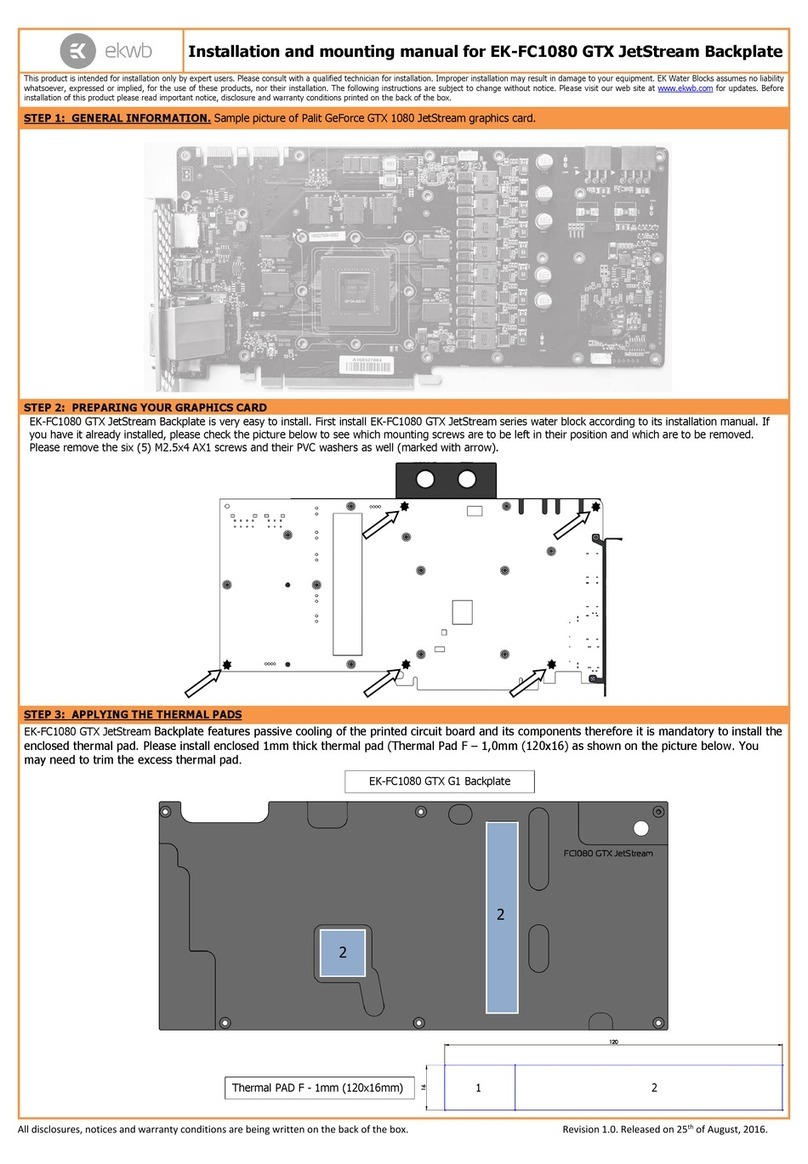
ekwb EK-FC1080 GTX JetStream Backplate Installation and mounting manuals

SilverStone
SilverStone TP02-M2 manual
WinSystems
WinSystems ITX-P-C444 quick start guide
Extron electronics
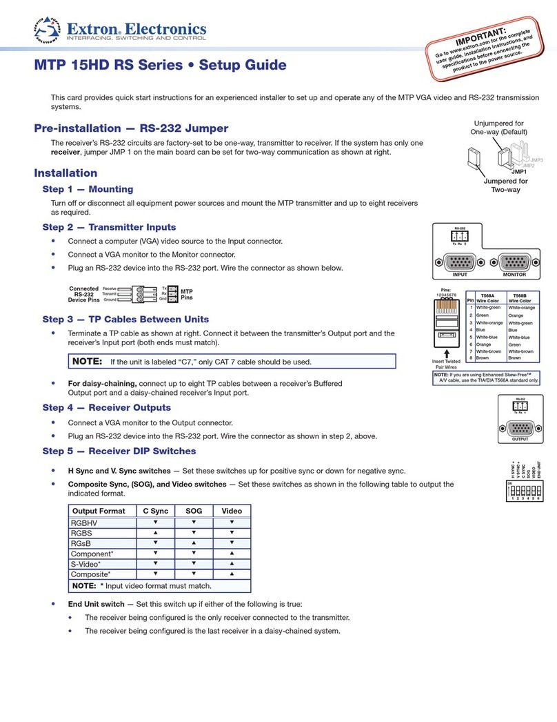
Extron electronics MTP 15HD RS Series Setup guide

Allied Telesis
Allied Telesis AT-2874SX Installation and user guide
Dolby Laboratories
Dolby Laboratories Lake LPD manual
