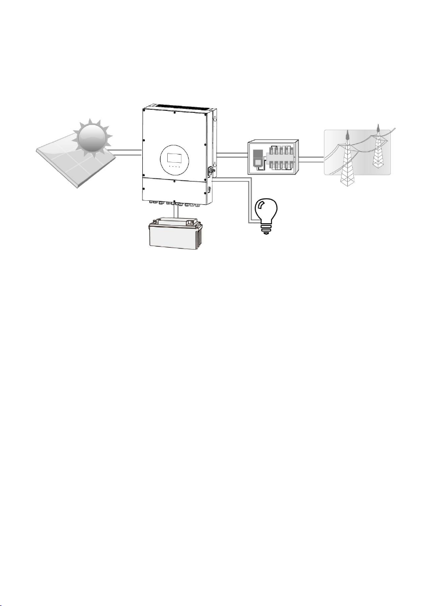
Master Battery MasterPower Omega LV 6KW User manual

Omega LV 6KW
PV Inverter Version: 1.1
User Manual

Table Of Contents
1. Introduction ....................................................................................................1
2. Important Safety Warning.................................................................................2
3. Unpacking & Overview .....................................................................................4
3-1. Packing List .............................................................................................4
3-2. Product Overview .....................................................................................4
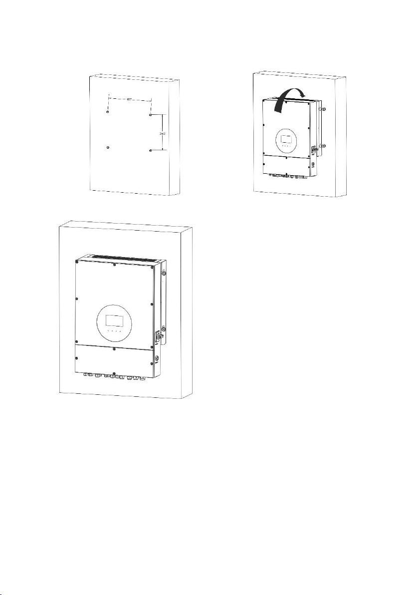
4. Installation ......................................................................................................5
4-1. Precaution ...............................................................................................5
4-2. Selecting Mounting Location......................................................................5
4.3. Mounting Unit ..........................................................................................5
5. Grid (Utility) Connection ...................................................................................7
5-1. Preparation..............................................................................................7
5-2. Connecting to the AC Utility.......................................................................7
6. Generator Connection.......................................................................................8
6-1. Preparation..............................................................................................8
6-2. Connecting to the Generator Input.............................................................8
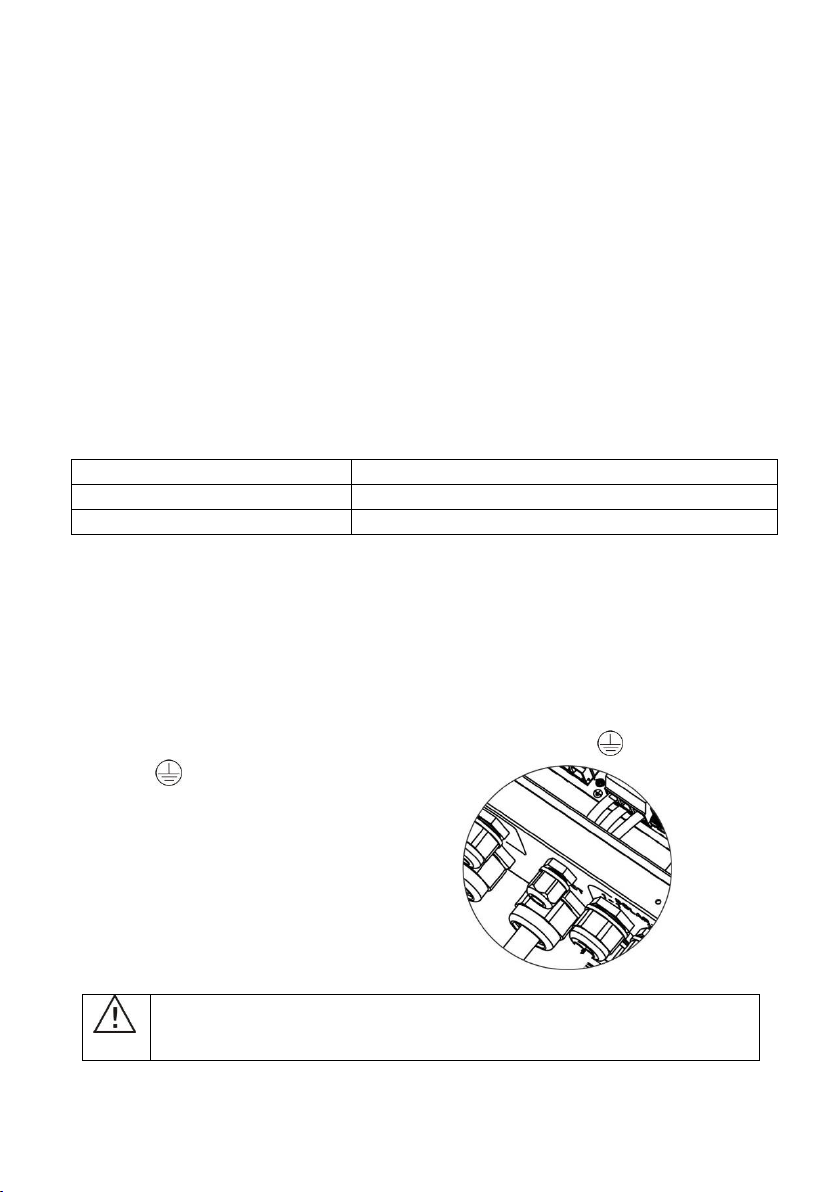
7. PV Module (DC) Connection ..............................................................................9
8. Battery Connection......................................................................................... 12
9. Load (AC Output) Connection.......................................................................... 13
8-1. Preparation............................................................................................ 13
8-2. Connecting to the AC output ................................................................... 13
9. Communication.............................................................................................. 15
9-1. Pin Assignment for RS-232 Communication Port........................................ 16
9-2. Pin Assignment for BMS Communication Port ............................................ 16
9-3. Dry Contact Signal.................................................................................. 16
10. Commissioning .............................................................................................. 18
11. Initial Setup................................................................................................... 19
12. Operation ...................................................................................................... 30
12-1. Interface.............................................................................................. 30
12-2. LCD Information Define......................................................................... 30
12-3. Touchable function keys ........................................................................ 32
12-4. LCD Setting.......................................................................................... 33
12-5. Query Menu Operation.......................................................................... 41
12-6. Operation Mode & Display ..................................................................... 46
13. Charging Management ................................................................................... 50
14. Maintenance & Cleaning ................................................................................. 52
15. Trouble Shooting............................................................................................ 53
15-1. Warning List......................................................................................... 53
15-2. Fault Reference Codes .......................................................................... 54
16. Specifications ................................................................................................ 56
Appendix I: Parallel Installation Guide...................................................................... 58
Appendix II: The Wi-Fi Operation Guide................................................................... 65

1
1. Introduction
This hybrid PV inverter can provide power to connected loads by utilizing PV power,
utility power and battery power.
Hybrid inverter
Battery
Figure 1 Basic hybrid PV System Overview
Depending on different power situations, this hybrid inverter is designed to generate
continuous power from PV solar modules (solar panels), battery, and the utility. When
MPP input voltage of PV modules is within acceptable range (see specification for the
details), this inverter is able to generate power to feed the grid (utility) and charge
battery. This inverter is only compatible with PV module types of single crystalline and
poly crystalline. Do not connect any PV array types other than these two types of PV
modules to the inverter. Do not connect the positive or negative terminal of the solar
panel to the ground. See Figure 1 for a simple diagram of a typical solar system with this
hybrid inverter.
PV modules
Distribution Box
Electric grids
Load

2
2. Important Safety Warning
Before using the inverter, please read all instructions and cautionary
markings on the unit and this manual. Store the manual where it can be
accessed easily.
This manual is for qualified personnel. The tasks described in this manual may be
performed by qualified personnel only.
General Precaution-
WARNING! Before installing and using this inverter, read all instructions and cautionary
markings on the inverter and all appropriate sections of this guide.
WARNING! Normally grounded conductors may be ungrounded and energized when a
ground fault is indicated.
WARNING! This inverter is heavy. It should be lifted by at least two persons.
CAUTION! Authorized service personnel should reduce the risk of electrical shock by
disconnecting AC, DC and battery power from the inverter before attempting any
maintenance or cleaning or working on any circuits connected to the inverter. Turning off
controls will not reduce this risk. Internal capacitors can remain charged for 5 minutes
after disconnecting all sources of power.
CAUTION! Do not disassemble this inverter yourself. It contains no user-serviceable
parts. Attempt to service this inverter yourself may cause a risk of electrical shock or fire
and will void the warranty from the manufacturer.
CAUTION! To avoid a risk of fire and electric shock, make sure that existing wiring is in
good condition and that the wire is not undersized. Do not operate the Inverter with
damaged or substandard wiring.
Conventions used:
WARNING! Warnings identify conditions or practices that could result in personal
injury;
CAUTION! Caution identify conditions or practices that could result in damaged to the
unit or other equipment connected.

3
CAUTION! Under high temperature environment, the cover of this inverter could be hot
enough to cause skin burns if accidentally touched. Ensure that this inverter is away
from normal traffic areas.
CAUTION! Use only recommended accessories from installer. Otherwise, not-qualified
tools may cause a risk of fire, electric shock, or injury to persons.
CAUTION! To reduce risk of fire hazard, do not cover or obstruct the cooling fan.
CAUTION! Do not operate the Inverter if it has received a sharp blow, been dropped, or
otherwise damaged in any way. If the Inverter is damaged, please call for an RMA
(Return Material Authorization).
CAUTION! AC breaker, DC switch and Battery circuit breaker are used as disconnect
devices and these disconnect devices shall be easily accessible.
Symbols used in Equipment Markings
Refer to the operating instructions
Caution! Risk of danger
Caution! Risk of electric shock
Caution! Risk of electric shock. Energy storage timed
discharge for 5 minutes.
Caution! Hot surface
Before working on this circuit
-Isolate inverter/Uninterruptible Power System (UPS)
-Then check for Hazardous Voltage between all
terminals including the protective earth.
Risk of Voltage Backfeed

4
3. Unpacking & Overview
3-1. Packing List
Before installation, please inspect the unit. Be sure that nothing inside the package is
damaged. You should have received the following items inside of package:
Inverter unit RS-232 cable Parallel cable Share current wires Manual Software CD
3-2. Product Overview
1) PV connectors
2) AC Grid connectors
3) Battery connectors
4) AC output connectors (Load
connection)
5) Generator input / Programmable
load output
6) External sensor port (reserved)
7) Dry contact & USB communication
port
8) BMS & RS-232 communication port
9) LCD display panel (Please check
section 10 for detailed LCD
operation)
10) Operation buttons
11) Current sharing port
12) Parallel communication port
13) PV switch
14) Cold start button

5
4. Installation
4-1. Precaution
This hybrid inverter is designed for indoor or outdoor use (IP65), please make sure the
installation site meets below conditions:
Not in direct sunlight
Not in areas where highly flammable materials are stored.
Not in potential explosive areas.
Not in the cool air directly.
Not near the television Antenna or antenna cable.
Not higher than altitude of about 2000 meters above sea level.
Not in environment of precipitation or humidity (>95%).
Please AVOID direct sunlight, rain exposure, snow laying up during installation and
operation.
4-2. Selecting Mounting Location
Please select a vertical wall with load-bearing capacity for installation, appropriate
for installation on concrete or other non-flammable surfaces.
The ambient temperature should be between -25~60℃to ensure optimal
operation.
Be sure to keep other objects and surfaces as shown in the diagram to guarantee
sufficient heat dissipation and have enough space for removing wires.
For proper air ventilation to dissipate heat, allow a clearance of approx. 50cm to
the side and approx. 50cm above and below the unit. And 100cm toward the front.
4.3. Mounting Unit
Installation to the wall should be implemented with the proper screws. After that, the
device should be bolted on securely.
The inverter only can be used in a CLOSED ELECTRICAL OPERATING AREA. Only service
person can enter into this area.
WARNING!! Remember that this inverter is heavy! Please be carefully when lifting out
from the package.
WARNING!! FIRE HAZARD.
SUITABLE FOR MOUNTING ON CONCRETE OR OTHER NON-COMBUSTIBLE SURFACE
ONLY.

6
1. Fix four screws as shown in the
chart. The reference tightening
torque is 35 N.m.
2. Raise the inverter and place it over
the four screws.
3. Check if the inverter is firmly
secured.

7
5. Grid (Utility) Connection
5-1. Preparation
NOTE 1: The overvoltage category of the AC input is III. It should be connected to the
power distribution.
NOTE 2: Before connecting to grid, please install a separate AC breaker between
inverter and grid. This will ensure the inverter can be securely disconnected during
maintenance and fully protected from over current. The recommended of AC breaker is
40A/300V.
WARNING! It's very important for system safety and efficient operation to use
appropriate cable for grid (utility) connection. To reduce risk of injury, please use the
proper recommended cable size as below.
Suggested cable requirement for AC wire
Nominal Grid Voltage
120VAC per phase
Conductor cross-section (mm2)
10-16
AWG no.
8-6
5-2. Connecting to the AC Utility
Please follow below steps to implement AC input connection:
1. Before making AC input connection, be sure to open DC protector or disconnector
first.
2. Remove insulation sleeve 7mm for four conductors.
3. Insert AC input wires according to polarities indicated on terminal block and tighten
the terminal screws. Be sure to connect PE protective conductor ( ) first.
→Ground (yellow-green)
L1→LINE (black)
L2→LINE (brown)
N→Neutral (blue)
WARNING:
Be sure that AC power source is disconnected before attempting to
hardwire it to the unit.

8
6. Generator Connection
There are two functions with this port:
Allows generator input as power source
Allows second AC output connect. This output can be turned On or Off by setting
battery voltage.
6-1. Preparation
NOTE 1: The overvoltage category of the AC input is III. It should be connected to the
power distribution.
NOTE 2: Before connecting to grid, please install a separate AC breaker between
inverter and grid. This will ensure the inverter can be securely disconnected during
maintenance and fully protected from over current. The recommended of AC breaker is
40A/300V.
WARNING! It's very important for system safety and efficient operation to use
appropriate cable for generator connection. To reduce risk of injury, please use the
proper recommended cable size as below.
Suggested cable requirement
Nominal Grid Voltage
120VAC per phase
Conductor cross-section (mm2)
10-16
AWG no.
8-6
6-2. Connecting to the Generator Input
Please follow below steps to implement generator input connection:
1. Before making generator input connection, be sure to open DC protector or
disconnector first.
2. Remove insulation sleeve 7mm for four conductors.
3. Insert input wires according to polarities indicated on terminal block and tighten the
terminal screws. Be sure to connect PE protective conductor ( ) first.
→Ground (yellow-green)
L1→LINE (black)
L2→LINE (brown)
N→Neutral (blue)
WARNING:
Be sure that generator power source is disconnected before attempting
to hardwire it to the unit.

9
7. PV Module (DC) Connection
CAUTION: Before connecting to PV modules, please install separately a DC circuit
breaker between inverter and PV modules.
NOTE1: Please use 1000VDC/20A circuit breaker.
NOTE2: The overvoltage category of the PV input is II.
Please follow below steps to implement PV module connection:
Step 1: Check the input voltage of PV array modules. The acceptable input voltage of the
inverter is 120VDC - 600VDC. This system is applied with two strings of PV array. Please
make sure that the maximum current load of each PV input connector is 15A.
Step 2: Disconnect the circuit breaker and switch off the DC switch.
Step 3: Remove insulation sleeve 7 mm for positive and negative conductors.
Step 4: Check correct polarity of connection cable from PV modules and PV input
connectors. Then, connect positive pole (+) of connection cable to positive pole (+) of
PV input connector. Connect negative pole (-) of connection cable to negative pole (-) of
PV input connector.
CAUTION: Exceeding the maximum input voltage can destroy the unit!! Check the
system before wire connection.
WARNING: Because this inverter is non-isolated, only two types of PV modules are
acceptable: single crystalline and poly crystalline with class A-rated.
To avoid any malfunction, do not connect any PV modules with possibility of leakage
current to the inverter. For example, grounded PV modules will cause leakage current to
the inverter.
CAUTION: It’s requested to have PV junction box with surge protection. Otherwise, it
will cause inverter damage when lightning occurs on PV modules.

10
WARNING! It's very important for system safety and efficient operation to use
appropriate cable for PV module connection. To reduce risk of injury, please use the
proper recommended cable size as below.
Conductor cross-section (mm2)
AWG no.
4
12
CAUTION: Do NOT touch the inverter to avoid electric shock. When PV modules are
exposed to sunlight, it may generate DC voltage to the inverter.
CAUTION: Never directly touch terminals of the inverter. It will cause lethal electric
shock.

11
Recommended Panel Configuration
Specifications
Solar panel
Nominal Max. Power (Pmax) (W)
430
455
520
535
Opt. Operating Voltage (Vmp) (V)
40.3
41.3
41.6
41.9
Opt. Operating Current (Imp) (A)
10.68
11.02
12.5
12.77
Open Circuit Voltage (Voc) (V)
48.3
49.3
49.14
49.44
Short Circuit Current (Isc) (A)
11.37
11.66
13.23
13.5
For 7.5KW input recommendation
Numbers in series of MPPT1
12
11
11
10
Numbers of strings in MPPT1
1
1
1
1
Maximum input voltage of MPPT1 (V)
579.6
542.3
540.54
494.4
Input power of MPPT1 (W)
5160
5005
5720
5350
Numbers in series of MPPT2
6
6
4
5
Numbers of strings in MPPT2
1
1
1
1
Maximum input voltage of MPPT1 (V)
289.8
295.8
196.56
247.2
Input power of MPPT2 (W)
2580
2730
2080
2675
Total input power (W)
7740
7735
7800
8025
Minimum input recommendation
Numbers in series of MPPT1
5
5
5
5
Numbers of strings in MPPT1
1
1
1
1
Maximum input voltage of MPPT1 (V)
241.5
246.5
245.7
247.2
Input power of MPPT1 (W)
2150
2275
2600
2675
Numbers in series of MPPT2
5
5
5
5
Numbers of strings in MPPT2
1
1
1
1
Maximum input voltage of MPPT1 (V)
241.5
246.5
245.7
247.2
Input power of MPPT2 (W)
2150
2275
2600
2675
Total input power (W)
4300
4550
5200
5350

12
8. Battery Connection
CAUTION: Before connecting to batteries, please install separately a DC circuit
breaker between inverter and batteries.
NOTE1: Please only use sealed lead acid battery, vented and Gel battery. Please check
maximum charging voltage and current when first using this inverter. If using Lithium
iron or Nicd battery, please consult with installer for the details.
NOTE2: Please use 60VDC/200A circuit breaker.
NOTE3: The overvoltage category of the battery input is II.
Please follow below steps to implement battery connection:
Step 1: Check the nominal voltage of batteries. The nominal input voltage for inverter is
48VDC.
Step 2: Use two battery cables. Remove insulation sleeve
10 mm and insert conductor into cable ring terminal.
Refer to right chart.
The cable size of each inverter is shown as below:
Recommended battery cable and terminal size for each inverter:
Model
Wire Size
Ring Terminal
Torque value
Cable mm2
Dimensions
D (mm)
L (mm)
LV 6KW
3/0
85
8.4
54.2
7~12 Nm
WARNING: Be sure the length of all battery cables is the same. Otherwise, there will
be voltage difference between inverter and battery to cause parallel inverters not
working.
Step 3: Insert battery wires according to polarities indicated on the terminal block and
tighten the terminal screws. Make sure polarity at both the battery and the inverter/charge
is correctly connected.
RED cable to the positive terminal (+);
BLACK cable to the negative terminal (-).

13
WARNING! Wrong connections will damage the unit permanently.
Step 4: Make sure the wires are securely connected. The reference tightening torque is
5.5~7.0 N.m.
WARNING! It's very important for system safety and efficient operation to use
appropriate cable for battery connection. To reduce risk of injury, please use the proper
recommended cable size as below.
Nominal Battery Voltage
48V
Conductor cross-section (mm2)
85
AWG no.
3/0
Protective earthing (battery side)
150mm2(300kcmil)
9. Load (AC Output) Connection
8-1. Preparation
CAUTION: To prevent further supply to the load via the inverter during any mode of
operation, an additional disconnection device should be placed on in the building wiring
installation.
WARNING! It's very important for system safety and efficient operation to use
appropriate cable for AC connection. To reduce risk of injury, please use the proper
recommended cable size as below.
Nominal Grid Voltage
120/208/240 VAC per phase
Conductor cross-section (mm2)
5.5-10
AWG no.
10-8
8-2. Connecting to the AC output
Step 1: Before making output connection, be sure to open DC protector or disconnector
first.
Step 2: Remove insulation sleeve 7mm for four conductors.
Step 3: Insert AC input wires according to polarities indicated on terminal block and
tighten the terminal screws. Be sure to connect PE protective conductor ( ) first.
→Ground (yellow-green)
L1→LINE (black)
L2→LINE (brown)
N→Neutral (blue)

14
The reference tightening torque is 1.0-1.5 N.m.
Step 4: Make sure the wires are securely connected.
CAUTION: Appliances such as air conditioner are required at least 2~3 minutes to
restart because it’s required to have enough time to balance refrigerant gas inside of
circuits. If a power shortage occurs and recovers in a short time, it will cause
damage to your connected appliances. To prevent this kind of damage, please check
manufacturer of air conditioner if it’s equipped with time-delay function before
installation. Otherwise, this inverter/charger will trig overload fault and cut off output
to protect your appliance but sometimes it still causes internal damage to the air
conditioner.
CAUTION: Do NOT connect the utility to “AC Output Connector (Load connector)”.
CAUTION: Be sure to connect L terminal of load to L terminal of “AC Output
Connector(Load connector)” and N terminal of load to N terminal of “AC Output
Connector(Load connector)”. The G terminal of “AC Output Connector”is connected to
grounding of the load. Do NOT mis-connect.

15
9. Communication
The inverter is equipped with several communication ports and it is also equipped with a
slot for alternative communication interfaces in order to communicate with a PC with
corresponding software. Follow below procedure to connect communication wiring and
install the software.
Please install monitoring software in your computer. Detailed information is listed in the
next chapter. After software is installed, you may initial the monitoring software and
extract data through communication port.
Wi-Fi Connection
This unit is equipped with a Wi-Fi transmitter. Wi-Fi transmitter can enable wireless
communication between off-grid inverters and monitoring platform. Users can access
and control the monitored inverter with downloaded APP. You may find “SolarPower Wi-
Fi” app from the Apple® Store or “SolarPower” in Google® Play Store. All data loggers
and parameters are saved in iCloud. For quick installation and operation, please refer to
Appendix II - The Wi-Fi Operation Guide for details.

16
9-1. Pin Assignment for RS-232 Communication Port
Definition
PIN 1
RS232TX
PIN 2
RS232RX
PIN 3
NC
PIN 4
8~12V
PIN 5
NC
PIN 6
NC
PIN 7
NC
PIN 8
GND
9-2. Pin Assignment for BMS Communication Port
Definition
PIN 1
RS232TX
PIN 2
RS232RX
PIN 3
RS485B
PIN 4
NC
PIN 5
RS485A
PIN 6
CANH
PIN 7
CANL
PIN 8
GND
9-3. Dry Contact Signal
There is one dry contact available on the bottom panel. It could be used to
remote control for external generator.
Electric Parameter
Parameter
Symbol
Max.
Unit
Relay DC voltage
Vdc
30
V
Relay DC current
Idc
1
A
Note: The application of the dry contact should not exceed the electric parameter shown
as above. Otherwise, the internal relay will be damaged.

17
Function Description
Unit
Status
Condition
Dry contact port:
NO&C
NC&C
Power
Off
Unit is off and no output is powered.
Open
Close
Power On
Battery voltage is lower than setting
battery cut-off discharging voltage when
grid is available.
Close
Open
Battery voltage is lower than setting battery
cut-off discharging voltage when grid is
unavailable.
Close
Open
Battery voltage is higher than below 2
setting values:
1. Battery re-discharging voltage when
grid is available.
2. Battery re-discharging voltage when
grid unavailable.
Open
Close
You can set the related parameters in software. Refer to below chart:

18
10. Commissioning
Step 1: Check the following requirements before commissioning:
Ensure the inverter is firmly secured
Check if the open circuit DC voltage of PV module meets requirement (Refer to
Section 6)
Check if the open circuit utility voltage of the utility is at approximately same to
the nominal expected value from local utility company.
Check if connection of AC cable to grid (utility) is correct if the utility is required.
Full connection to PV modules.
AC circuit breaker (only applied when the utility is required), batter circuit breaker,
and DC circuit breaker are installed correctly.
Step 2: Switch on the battery circuit breaker and then switch on PV DC breaker. After
that, if there is utility connection, please switch on the AC circuit breaker. At this
moment, the inverter is turned on already. However, there is no output generation for
loads. Then:
If LCD lights up to display the current inverter status, commissioning has been
successfully. After pressing “ON”button for 1 second when the utility is detected,
this inverter will start to supply power to the loads. If no utility exists, simply press
“ON”button for 3 seconds. Then, this inverter will start to supply power to the
loads.
If a warning/fault indicator appears in LCD, an error has occurred to this inverter.
Please inform your installer.
Step 3: Please insert CD into your computer and install monitoring software in your PC.
Follow below steps to install software.
1. Follow the on-screen instructions to install the software.
2. When your computer restarts, the monitoring software will appear as shortcut icon
located in the system tray, near the clock.
Table of contents
Other Master Battery Inverter manuals