EcoFlow PowerStream User manual

USER MANUAL
V1.0
EcoFlow PowerStream
Microinverter

Disclaimer
Read this user manual carefully before using the product to ensure that you completely
understand the product and can correctly use it. After reading this user manual, keep
it properly for future reference. Improper use of this product may cause serious injury
to yourself or others, or cause product damage and property loss. Once you use this
product, it is deemed that you understand, approve and accept all the terms and
content in this document. EcoFlow is not liable for any loss caused by the user's failure
to use this product in compliance with this user manual.
In compliance with laws and regulations, EcoFlow reserves the right to final
interpretation of this document and all documents related to this product. This
document is subject to changes (updates, revisions, or termination) without prior notice.
Please visit EcoFlow's official website to obtain the latest product information.
Hereby, EcoFlow Inc. declares that EcoFlow PowerStream
Microinverter is in compliance with Directive 2014/53/EU. The
full text of the EU declaration of conformity is available at the
following internet addresses:
http://www.ecoow.com/eu/eu-compliance
http://www.ecoow.com/de/eu-compliance
http://www.ecoow.com/fr/eu-compliance
Hereby, EcoFlow Inc. declares that EcoFlow PowerStream
Microinverter is in compliance with Radio Equipment
Regulations 2017. The full text of the UKCA declaration of
conformity is available at the following internet address:
http://www.ecoow.com/uk/eu-compliance
The Bluetooth
®
word mark and logos are registered trademarks
owned by Bluetooth SIG, Inc. and any use of such marks by
EcoFlow Inc. is under license. Other trademarks and trade
names are those of their respective owners.
The crossed-out wheeled bin indicates that the electrical and
electronic (EE) product should not be discarded as unsorted
waste but must be sent to separate collection facilities for
recovery and recycling.

Contents
Safety Instruction 1
General safety 1
Environment requirements 1
Explanation of Symbols 2
Symbols on the decumentation 2
Symbols on the device 2
What's in the Box 3
Overview 4
System overview 4
Product overview 5
LED indication 6
Assembly 7
Pre-assembly 7
Assembly procedure 8
Connecting several solar panels in series or in parallel 13
Mounting the microinverter 17
Grounding considerations 19
EcoFlow App 20
Page of your PowerStream balcony solar system 20
Page of your microinverter 22
Unplug the Cables 23
Troubleshooting 24
Specifications 25

General safety
Safety Instruction
1.Please carefully read the documents before installing, operating or maintaining the equipment.
The documents are subject to change due to product updates or other reasons.
2.Do not put heavy objects on the equipment.
3.Ensure that all cables and connectors are intact and dry before connecting to prevent electric
shocks.
4.Use insulation tools or wear personal protective equipment when you install or operate the
equipment.
5.Do not install or operate the equipment in extreme weather events such as lightning, snow,
heavy rain, strong wind and so on.
6.Do not damage, smear or rip off any warning labels on the equipment.
7.Do not hit, pull, drag, squeeze or step on the equipment, or throw it into the re, as there is risk
of explosion.
8.After installing, please clean the remains of the installation, such as boxes, clipped cable ties,
ripped insulation materials, etc.
9.Do not modify or repair the equipment, please contact our customer service or qualied
personnel if necessary.
10.Use tools and the equipment correctly to prevent personal injuries and product damage.
11.Understand the components and function of the grid-tied PV power system. Make sure that
all electrical connections, and voltage and frequency at the connection point meet the local
microinverter grid-tie requirements.
12. Make sure the screws are tightened to the specied torque during installation (M5*12: 30
Kgf*cm; ST5*12: 45 Kgf*cm; M6*20: 90 Kgf*cm).
13.Make sure that the ground wire is tightly connected. The cross-section of ground wire should
be ≥ 4 mm².
14.It is strongly recommended to install an overcurrent circuit breaker between the equipment
and the grid.
15.The equipment may get more than 70 °C (158 °F) while in use. Do not touch its enclosure
before it cools down. Also, always keep the equipment out of reach of children and pets.
16.The installation location should be convenient for you to pull out the connectors.
17.Before you pull out the AC (or battery) connector from the microinverter, disconnect the cable
from the AC socket (or battery's) end.
18.Make sure the portable power station is off during the whole connection process.
Environment requirements
1.Make sure the equipment is intalled, operated or stored in a well ventilated place.
2.Do not install or operate the equipment near flammable, explosive, corrosive, caustic or moist
sources.
3.Do not expose the equipment to strong electromagnetic fields to avoid radio interference.
1

Explanation of Symbols
Symbol Explanation Symbol Explanation
Refer to the operation
instructions
Caution, risk of electric shock;
energy storage timed discharge
Caution, hot surface The position for connecting the
protection ground cable
Caution, risk of danger Ingress Protection rating
Symbols on the decumentation
Symbols on the device
Symbol Explanation Symbol Explanation
A hazard with a high level of risk
which, if not avoided, will result in
death or serious injury.
A hazard with a low level of risk
which, if not avoided, will result
in minor injury, or demage to the
device.
Important information that you need
to pay attention to.
In a basic set
Indicates additional
information on correct
use or useful tips.
Optional (not in the
box)
DANGER
NOTICE
CAUTION
Do not damage, smear or cover any warning lables on the device. All labels
must be visible after installation.
DANGER
2

What's in the Box
M6*20
M5*12
Protective case
Installation board
BKW-Solar cable
• The images of the product and components may differ from the actual product.
• If there are missing or defective components, please contact EcoFlow customer
service.
PowerStream Microinverter
A B
CD
M5*40
F
E
ST5.5*25
G
H
M6 nut
I
Cable puller
J
X2 X1
X1
X1 X1
X2
X2X3
X1
X2
Used for mounting the microinverter on the wall. See "Mount on
the wall" for details.
Used for mounting the microinverter on the bracket. See "Mount
on the bracket" for details.
Used for disconnection, located at the bottom of the protective
case. See "Unplug the Cables" for details.
D
D E G
H I
J
F
F
3

Overview
No. Name Description In a basic set / Optional
(not in the box)
1 Solar panel Up to two groups of solar panels can be
connected to one microinverter.
2Extension
cable
Used for extending the connection
between the microinverter and the solar
panel.
3Super flat
cable
Used for passing through a window or a
door.
4BKW-Solar
cable
Used for the connection between the
microinverter and the solar panel.
5PowerStream
Microinverter /
6
Battery
connection
cable
Used for the connection between the
microinverter and the EcoFlow portable
power station.
Three types: BKW-DELTA EB cable,
BKW-DELTA PRO cable, BKW-RIVER
cable.
7
EcoFlow
portable power
station
Used for power storage.
System overview
123
6
7
9
4
5
8
2.4G
5
8
4
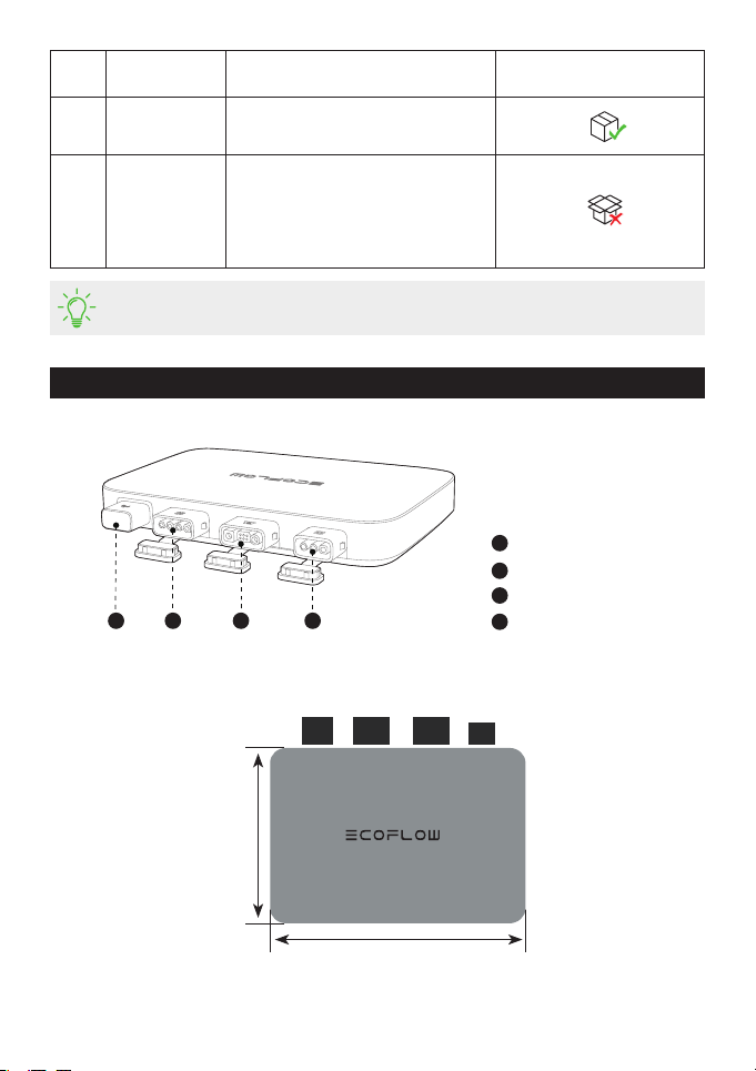
Antenna
PV port
Battery port / DC port
AC output port
Product overview
1
1
2
2
3
3
44
You can purchase optional accessories from the official EcoFlow website.
No. Name Description In a basic set / Optional
(not in the box)
8BKW-AC cable Used for connection of the
microinverter to the power grid.
9EcoFlow Smart
Plug
Used for monitoring the power
of appliances and for wireless
communication with the microinverter
to optimize the energy usage.
242 mm
169 mm
5

White
Solid Power on
There is PV input or/and the power station
discharges (DC input), without any power
output.
Breathing Charging There is PV input and the power station is
charged (DC output), without AC out.
Purple Blinking Updating Updating the rmware.
Blue Blinking Pairing Pairing with EcoFlow app.
Yellow Solid Warning See "Troubleshooting" for details.
Red Solid Error See "Troubleshooting" for details.
LED
indicator Color Status
Feeding
electricity
(power grid)
Feeding
electricity
(Smart Plug)
Detailed explanation
Green
Breathing
There is power input and
AC output. Electricity is fed
to Smart Plug(s) for use by
appliances.
Solid
There is power input and
AC output, but no electricity
is fed to Smart Plug(s).
LED indication
6

Assembly
Pre-assembly
Select a location for the PowerStream Microinverter
2.4G
2.4G
.
Do not place or install the microinverter in an area where flammable or explosive materials
are stored.
Make sure that the microinverter is within the Wi-Fi coverage.
The IP rating of the microinverter is IP 67, hence, it can be installed either indoors or outdoors.
However, the EcoFlow portable power station is not waterproof. If your system includes a
portable power station, keep both of them indoors.
.
• This user manual only provides the cable connection method and the
mounting method for the microinverter. For installing the solar panel,
please refer to the instructions for the solar panel and its accessories.
• If you wish to verify the solar system, complete the assembly on a sunny
day.
NOTICE
7
This manual suits for next models
2
Table of contents
Other EcoFlow Inverter manuals


