Must PH1800 PLUS 4K User manual
Service Manual
PH1800 PLUS 4K/5K
Inverter/Charger
PH1800 PLUS 4K/5K
Service Manual

Service Manual
PH1800 PLUS 4K/5K
Table of Contents
1. General Information.................................................................................................... 1
1.1 Brief Introduction ....................................................................................................1
1.2 Basic Topology Introduction....................................................................................1
1.3 Overview of Inverter/Charger..................................................................................2
2. Fault and Troubleshooting.......................................................................................... 3
3. Maintenance Step....................................................................................................... 4
3.1 Maintenance...........................................................................................................4
3.1.1 To Check DC FUSE and Capacitance............................................................4
3.1.2 DC/DC Boost Module.....................................................................................5
3.1.3 Divers.............................................................................................................7
3.2 To Check BUS Module...........................................................................................11
3.2.1 Power Devices...............................................................................................11
3.2.2 IGBT Diver Circuit..........................................................................................12
3.3 To Check BUCK Circuit..........................................................................................13
3.3.1 Power Devices...............................................................................................13
3.3.2 Divers.............................................................................................................14
3.4 To Check Invert Full Bridge.....................................................................................15
3.4.1 To Inspect Power Components as below........................................................15
3.4.2 To Check Drivers............................................................................................15
3.5 To Check BUS Soft Start Circuit.............................................................................17
3.5.1 Plug-in Components.......................................................................................17
3.6 To Check the AC Switch-on Power Supply Circuit..................................................19
3.7 To Check the Battery Switch-on Power Supply Circuit...........................................21
3.8 To Check the MOSFETS for Reversed Protection on DC Terminal.......................23
3.9 To Check NTC Circuit.............................................................................................23
3.9.1 NTC in Position of HS1 Plug-in Position of CN8 on Main Board....................24
3.9.2 NTC1 Under Transformer...............................................................................26
3.9.3 NTC4 in HS3..................................................................................................26
3.10 To Check Fan Driver Circuit on Main Board..........................................................28
4. Other Common Faulty Cases......................................................................................28
4.1 MOSFET Burnt.......................................................................................................28
4.2 Input Cable Disconnection......................................................................................29
4.3 Dust-covered Control Board...................................................................................29
5. Assembling Guidance..................................................................................................29
6. Test Guidance after Repairing.....................................................................................33

Service Manual
PH1800 PLUS 4K/5K
- 1 -
1. General Information
1.1 Brief Introduction
This manual is used as a tool of inspection and repairing guidance for
PH18-4K/5K MPK (F), as well as instructions of assembling and testing. It is
best to have some electrical or electronic background knowledge. With this
guidance, hope it will help you to check and inspect the inverter/charger first by
yourself.
1.2 Basic Topology Introduction
The topology for 4KVA/5KVA shows as below:

Service Manual
PH1800 PLUS 4K/5K
- 2 -
1.3 Over review and Introduction of Inverter /charger Parts
LCD Display
Solar Charge
Controller Board
Main Board
Service Manual
PH1800 PLUS 4K/5K
- 3 -
2. Fault and Troubleshooting
No LCD
display when
inverter turns
on
First to test battery volt to check whether it is in range of 44v-52v;
If it is in the range, to switch the inverter one to check whether the
unit starts. If the unit does not run yet, please disconnect all
connections and open the surface panel, take out the main board,
then to check and repair according to 3.7
01
First to replace the fan, to check whether it is okay; if NG, please
inspect the main board and repair according to 3.11
02
Please to check the main board and repair according to 3.9
03
Please to check first and then to repair the main board according
to 3.1, 3.6 and 3.7
06
First to start up the inverter by only connecting battery, if the fault
is still on, please inspect the main board following 3.4
08
To restart the inverter, to check whether the fault repeats, if yes, it
requires to replace the control boards.
09
To Check the main board following 3.1.2, 3.2.1, 3.4.1 and 3.5 and
to repair accordingly
52
First to restart inverter by only connecting to battery, if fault
continues, then to check the main board according to 3.1.2 and
3.4
56
First to check the connection of battery cable, if good connection,
then please to check and repair the main board following 3.1.1
and 3.1.2 accordingly
57
To replace the control board
58
First to restart inverter by connecting battery only, to check
whether it is good?
Second to connect battery and Utility but to keep switch off,
checking whether inverter charges battery? Otherwise, to check
and repair main board according to 3.1.2, 3.2.1 and 3.4.1
accordingly
72
To replace the control board
Service Manual
PH1800 PLUS 4K/5K
- 4 -
3. Steps to Repair
3.1 Battery Working Mode Test
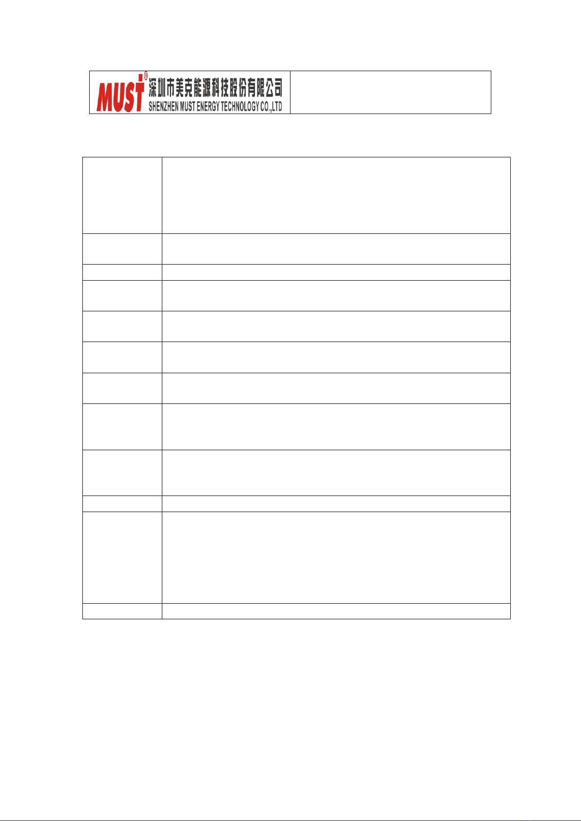
3.1.1 To Check DC FUSE and Capacitance
F3: 180-00045-00 (Fuse, 42*12*0.6mm, Purple Copper Plate with tin plated)
Positioning
Attribute
Reference Value
Failure Status
F3
Resistor
0 ohm
open
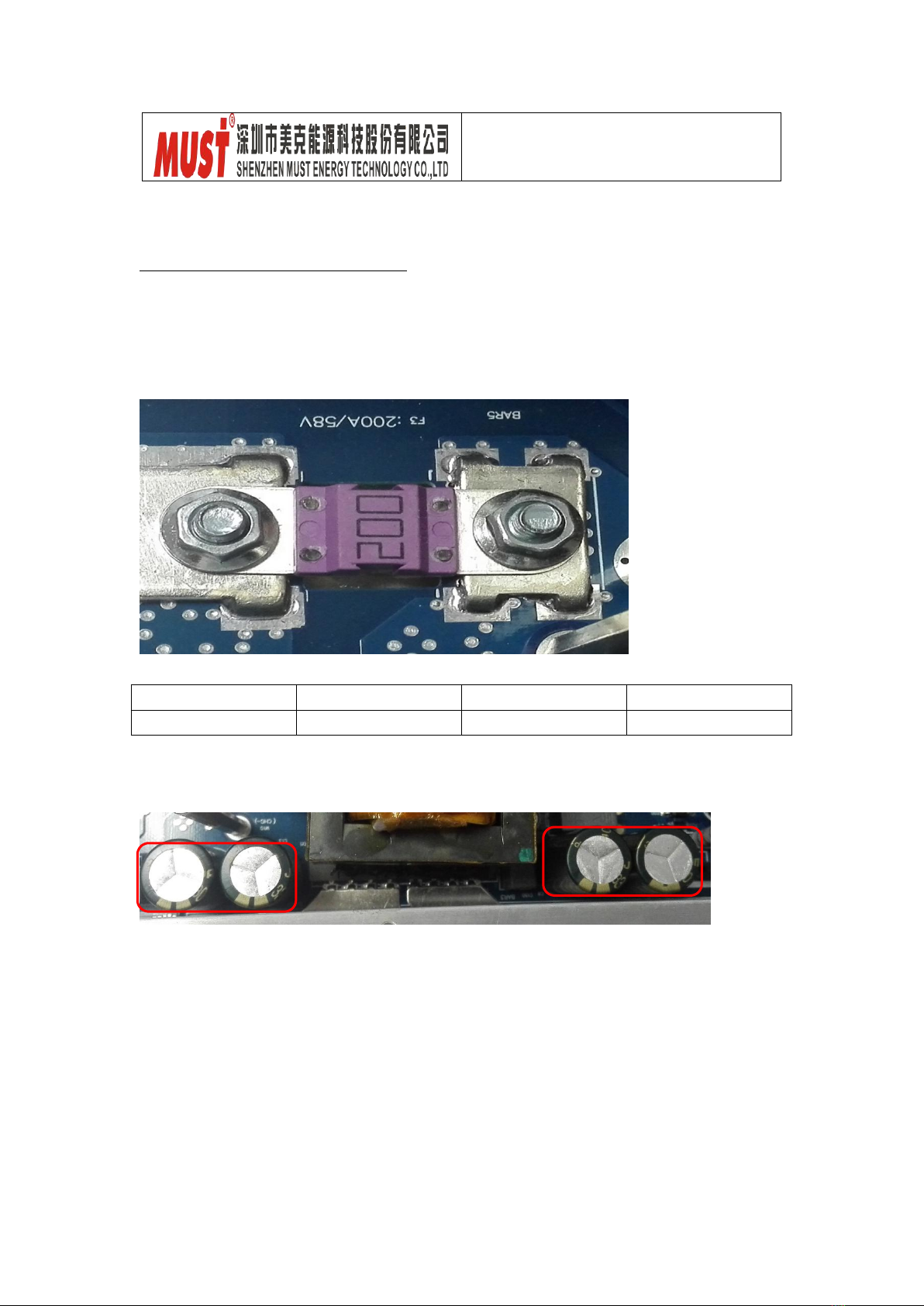
C8,C9,C12,C13: 140-00103-00 (Electrolytic Capacitor, AL 3300uF/63V 105℃18*45.5 BULK RAD)
If the capacitors explode as below, they need to be replaced.
Service Manual
PH1800 PLUS 4K/5K
- 5 -
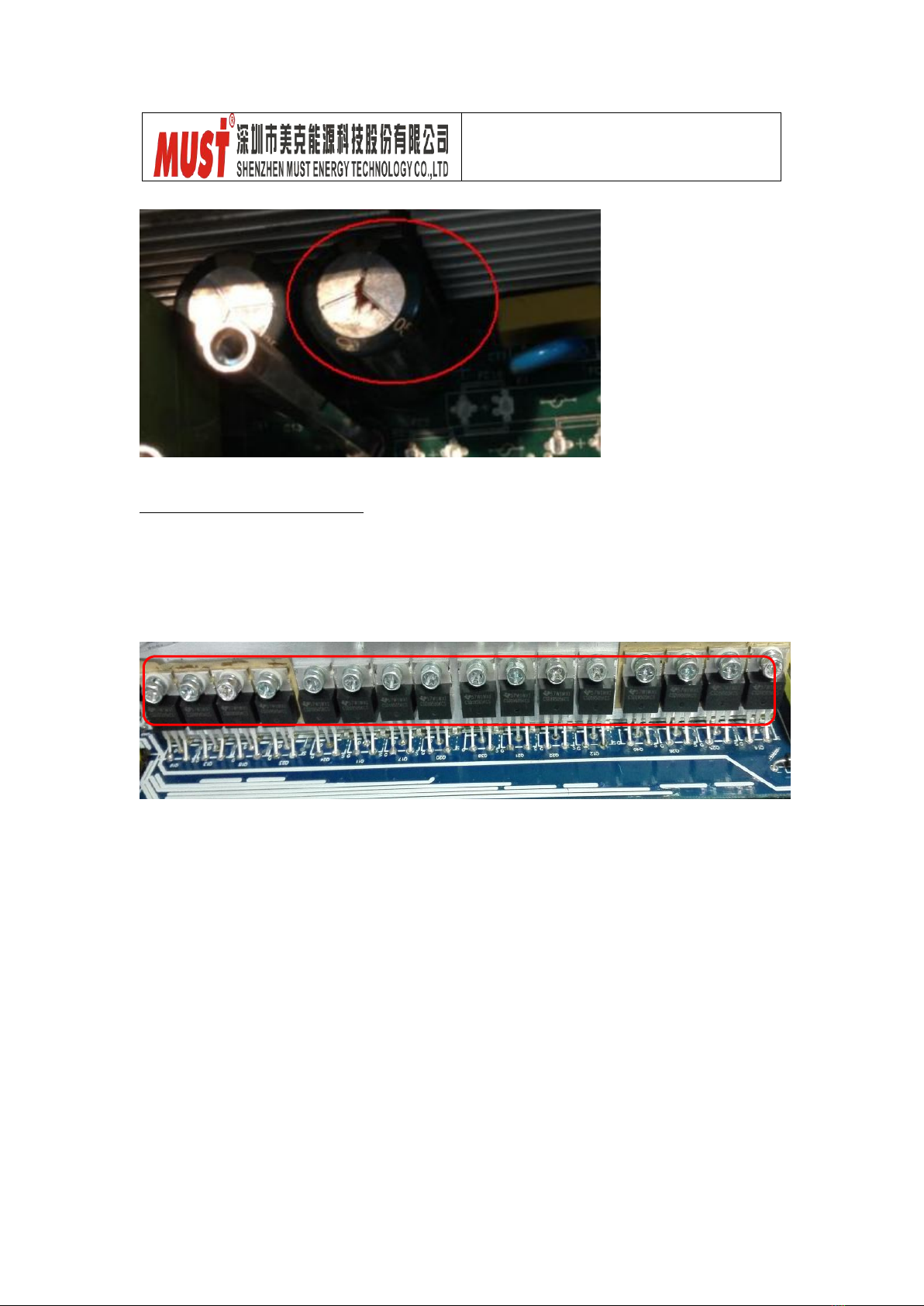
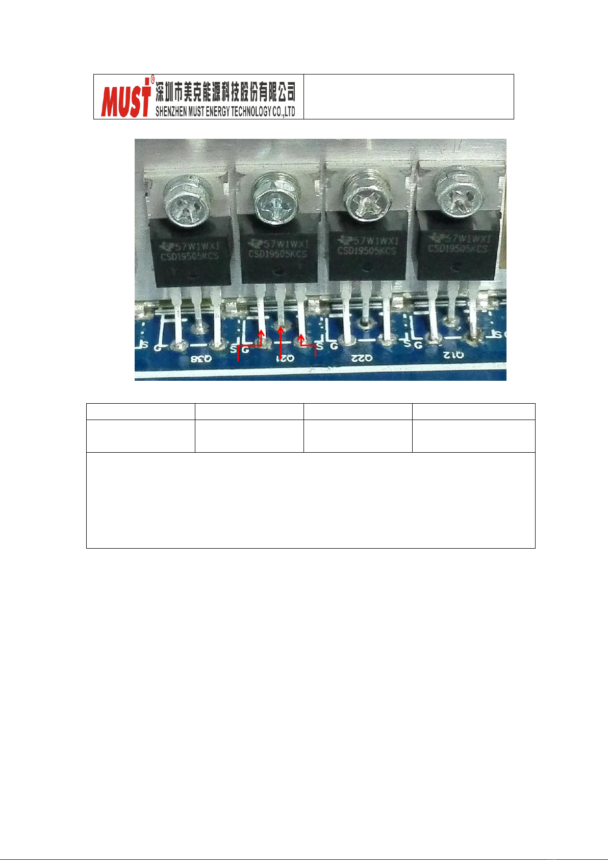
3.1.2 DC/DC Boost Module
DC/DC MOSFET:
Q14/Q25/Q26/Q40, Q12/Q22/Q21/Q38, Q20/Q17/Q11/Q24, Q13/Q18/Q13/Q19
150-00052-00: MOSFET TI/CSD19505KCS 201A 80V N BULK TO-220
Service Manual
PH1800 PLUS 4K/5K
- 6 -
Positioning
Attribute
Reference Value
Failure Status
All MOSFET, 16pcs
Diode
SD:0.44V
DS:OL
Short-circuit
or Explosion
Note 1: When you use multi-meter to measure the resistance of MOSFET, due to the
capacitor in the circuit, it will cause the continuous wave of the value when you measure the
DS and GD; therefore we would recommend to measure the diode forward voltage of SD and
the resistor of GS; these two values can reflect the situation of the transistor correctly.
Note 2: If one or more than one of them were broken, please replace all of them. For 4K, the
main board has just 12pcs MOSFETS.
G
D
S
Service Manual
PH1800 PLUS 4K/5K
- 7 -
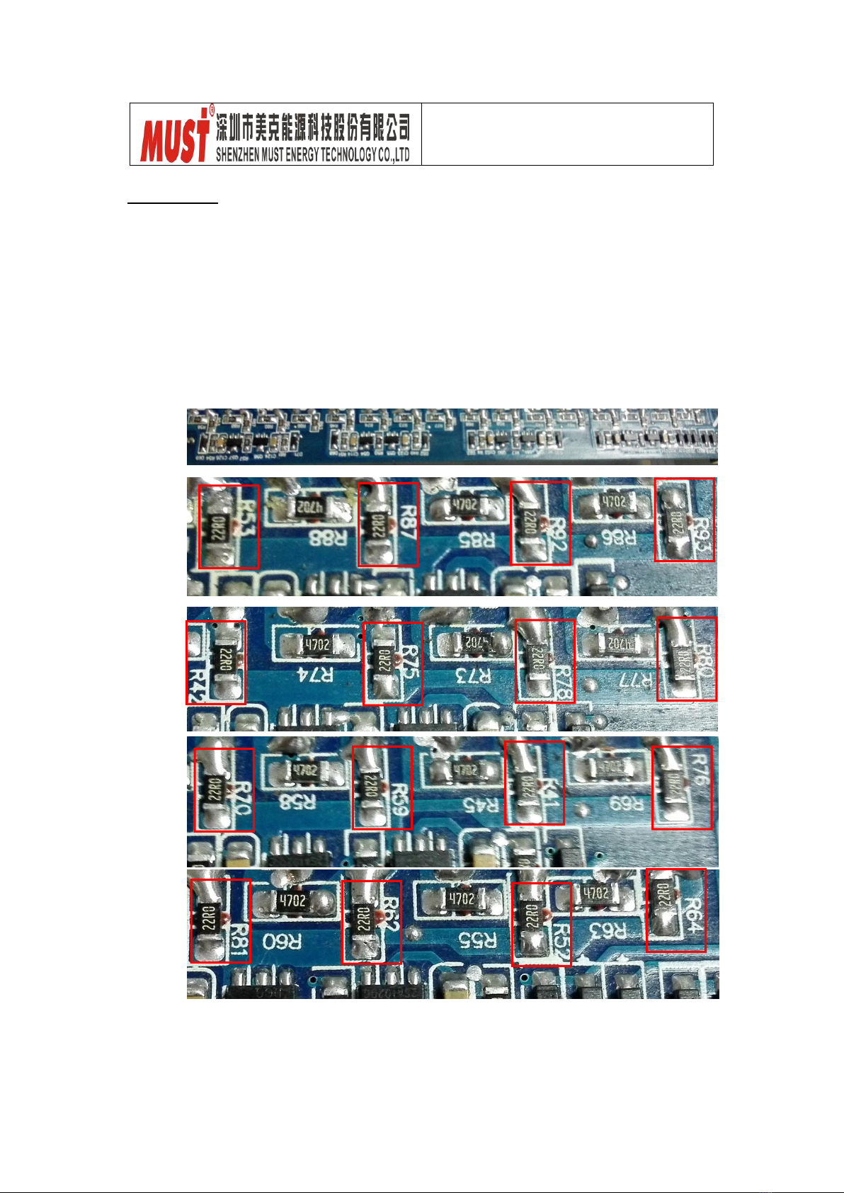
3.1.3 Divers
Note: when there are power devices or components are damaged, Divers are
usually required to check.
The reference resistors listed as below.
R53/R87/R92/R93, R42/R75/R78/R80, R70/R59/R41/R76, R81/R62/R52/R64
All the resistors are 100-10022-00 (RES CHIP TF1/4W 22F (1206))

Service Manual
PH1800 PLUS 4K/5K
- 8 -
E
Q43
Q16
To use Multi-meter to measure each resistors till to find out the broken ones
and to replace them, no need to change all the resistors.
Positioning
Attribute
Reference Value
Failure Status
All Resistors:
22 ohm
Resistor
22 ohm
Open Circuit
or other value
If resistors are need to replace, please check the diver transistors and
controlling IC.
Q46/Q48/Q41/Q43:150-00005-00 (Plug-in Transistor TOSHIBA/2SC2655-Y 2A 50V)
Q15/Q16/Q47/Q49:150-00004-00 (Plug-in Transistor TOSHIBA/2SA1020-Y 2A 50V)
Q48
Q49
Q47
Q46
Q15
B
C
Q41
Service Manual
PH1800 PLUS 4K/5K
- 9 -
E
B
C
Positioning
Attribute
Reference Value
Failure Status
Q46/Q48/Q41/Q43
Diode
BE:0.6V
BC:0.6V
CE:1V
Short-circuit or burnt
Q15/Q16/Q47/Q49
Diode
BE:0.6V
BC:1.3V
CE:0.2V
Short-circuit or burnt
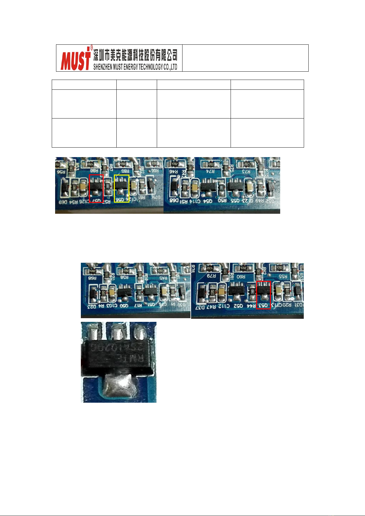
Q51/Q52/Q54/Q56:120-20035-00(SMD Transistors UTC/2SD1624 2A 50V NPN SOT-89)
Q50/Q53/Q55/Q57:120-20036-00 (SMD Transistors UTC/2SA1020 3A 50V PNP SOT-89)
C

Service Manual
PH1800 PLUS 4K/5K
- 10 -
G
S
Positioning
Attribute
Reference Value
Failure Status
Q51/Q52/Q54/Q56
Diode
BE:0.6V
BC:0.6V
CE:OL
Short Circuit or Burnt
Q50/Q53/Q55/Q57
Diode
BE:0.6V
BC:OL
CE:1V
Q60/Q61:120-20071-00 (MOSFET UTC/UT3404 5.8A 30V NPN SOT-23 SMD)
Positioning
Attribute
Reference Value
Failure Status
Q60/Q61
Diode
SD:0.18V DS1.2V
Short Circuit or Burnt
U9:160-00018-00(IC LINEAR SG3525ANG MOTOROLA L-1)
D
S

Service Manual
PH1800 PLUS 4K/5K
- 11 -
Q28
S
D
G
3.2 To Check BUS Module
3.2.1 Power Devices
DC/DC IGBT: Q27/Q28/Q29/Q30
Q27/Q28/Q29/Q30: 150-00048-00 (IR/IRGP4750DPBF 50A 650V)
Positioning
Attribute
Reference Value
Failure Status
Q27/Q28/Q29/Q30
Diode
EC:0.37V
CE:OL
Short Circuit
or Broken
Note: If there is one or more than one components broken, please replace them all.
Positioning
Attribute
Reference Value
Failure Status
U9
Resistor
Pin11-Pin12:5.4M
Pin13-Pin12:60K
Pin14-Pin12: 5.4M
Short Circuit
or Broken
Note: If you are not sure which component broken, we would like to suggest you to
replace them all.
Q30
Q29
Q27

Service Manual
PH1800 PLUS 4K/5K
- 12 -
3.2.2 IGBT Diver Circuit
R96/R91/R101/R102:100-10022-00 (Resistor CHIP TF 1/4W 22 F (1206))
R94/R90/R97/R99:100-10000-00 (Resistor CHIP TF 1/4W 0 F (1206))
D33/D32/D34/D35:120-20001-00(Diode PANJIT/1N4148W 0.15A 75V SOD123)
Positioning
Attribute
Reference Value
Failure Status
R96/R91/R101/R102
Resistor
22ohm
Open Circuit
or other value
R94/R90/R97/R99
Resistor
0ohm
D33/D32/D34/D35
Diode
+ to -:0.6V
- to +:OL
Short Circuit
or Broken
Note: When to test Diode, please remove the R94/R90/R97/R99 from main board,
otherwise test result will be not accurate.
+
-
Service Manual
PH1800 PLUS 4K/5K
- 13 -
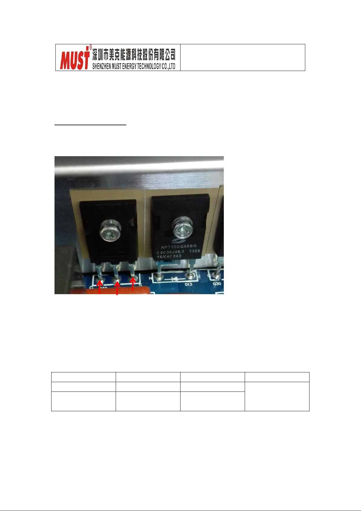
3.3 To Check BUCK Circuit
3.3.1 Power Devices
BUCK MOSFET and Diode: Q32/D13
Q32:150-00048-00 (IGBT IR/IRGP4750DPBF 50A 650V N BULK TO-247)
D13:150-10115-00 (Plug-in Diode APT30DQ60BG 30A 600V TO-247 2P)
Note: D13 is 150-10042-00 (Plug-in Diode FAIR/RHRP1560_NL 15A 600V)
Positioning
Attribute
Reference Value
Failure Status
Q32
Diode
SD:0.44V
Short Circuit
or Broken
D13
Diode
+ to -:0.36V
- to +:OL
Q32
D13
G
D
S
+
-

Service Manual
PH1800 PLUS 4K/5K
- 14 -
-
-
3.3.2 Divers
R125:100-10047-00 (SMD Resistor CHIP TF 1/4W 47 F (1206))
R124:100-10010-00 (SMD Resistor CHIP TF 1/4W 10 F (1206))
D38: 120-20001-00 (SMD Resistor PANJIT/1N4148W 0.15A 75V SOD123)
Positioning
Attribute
Reference Value
Failure Status
R125
Resistor
47 ohm
Short Circuit
or other Value
R124
Resistor
10 ohm
D38
Diode
+ to -: 0.6V
- to +: OL
Short Circuit
or Broken
Note: When testing diodes, please remove R124, or the result will be not accurate.
+
Service Manual
PH1800 PLUS 4K/5K
- 15 -
QB2
C
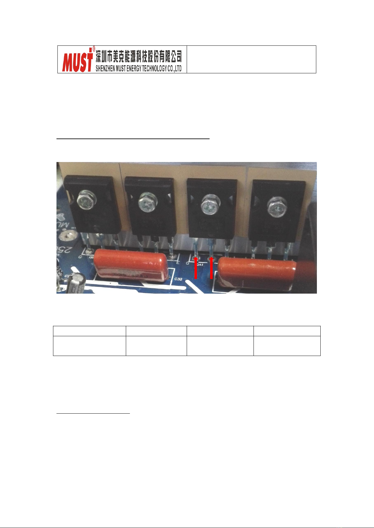
3.4 To Check Invert Full Bridge
3.4.1 To Inspect Power Components as below
INV IGBT: QA1/QB2/QC1/QD2
QA1/QB2/QC1/QD2: 150-30082-00 (IGBT IR/IRGP4066D-EPBF 75A 600V TO-247)
Positioning
Attribute
Reference Value
Failure Status
QA1/QB2/QC1/QD2
Diode
EC:0.4V
CE: OL
Short Circuit
or Burnt
Mark 1: if one or more than one IGBT broken, all IGBT components should be replaced.
Mark2: this is for PH18-4K model.
A1/QB2/QC1/QD2: 150-30088-00 (IGBT IR/IRGP4063D-EPBF 48A 600V TO-247)
3.4.2 To Check Divers
R150/R137/R139/R48/R152/R140/R145/R144: 100-10047-00
(Chip Resistor, CHIP TF 1/4W 47 F (1206))
D16/D5/D12/D6: 120-20001-00 (Chip Diode, PANJIT/1N4148W 0.15A 75V SOD123)
QC1
QA1
G
QD2
E

Service Manual
PH1800 PLUS 4K/5K
- 16 -
1
-
1
-
Positioning
Attribute
Reference Value
Failure Status
All Resistors
Resistor
47 ohm
Other value or
Open Circuit
D16/D5/D12/D6
Diode
EC: 0.6V
CE: OL
Short Circuit
or Burnt
Mark: When testing the diodes, please remove the R139/R150/R150/R145, or the test
result is not current.
Optocoupler: U12/U2/U4/U1/U3
U12/U2/U4/U1/U3:120-10065-00(Chip Optocoupler: FOD3120 SMT)
Positioning
Attribute
Reference Value
Failure Status
U12/U2/U4/U1/U3
Resistors
Pin8-Pin5:2K
Pin7-Pin5:2K
Short Circuit
or Burnt
8
+
Service Manual
PH1800 PLUS 4K/5K
- 17 -
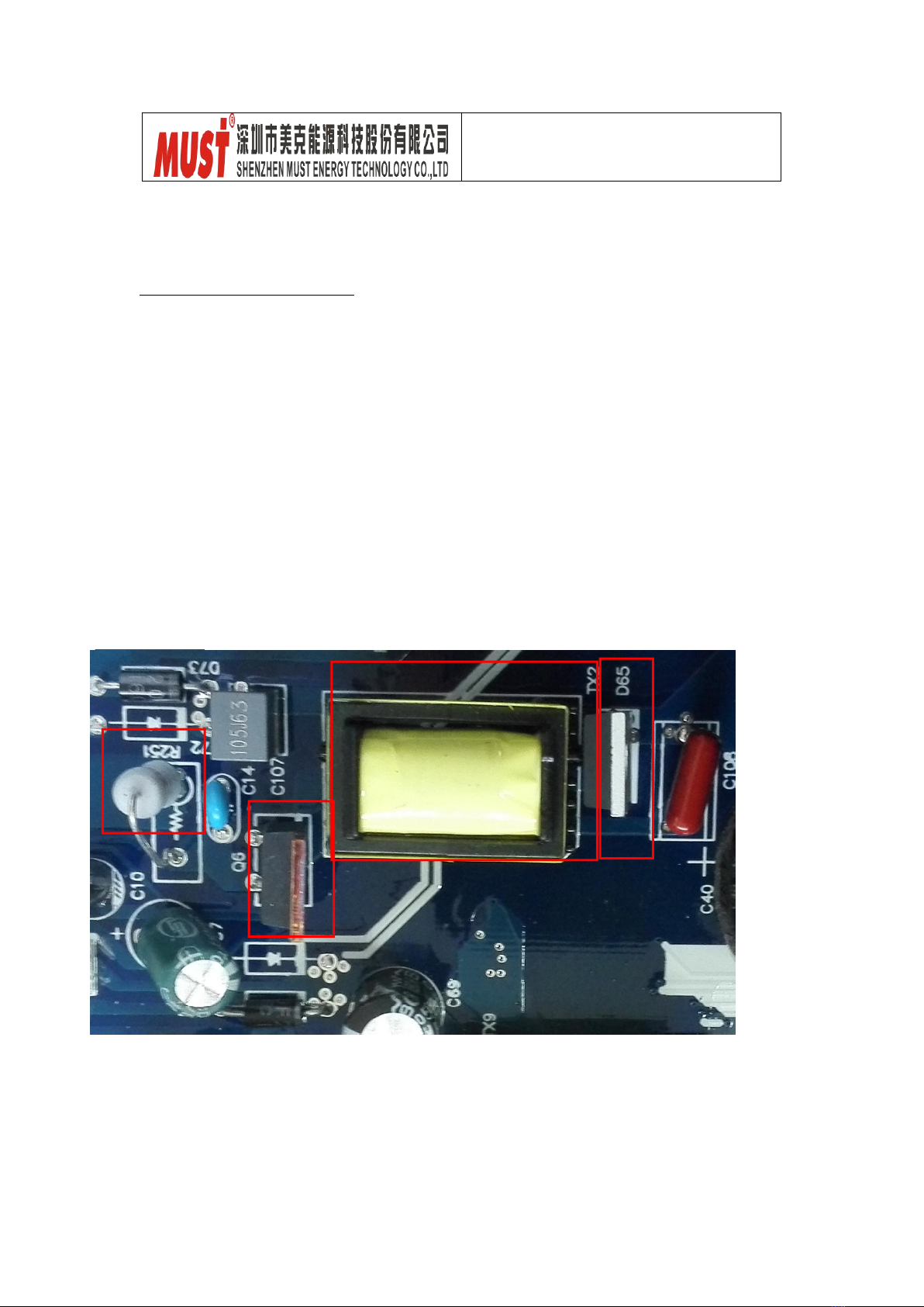
3.5 To Check BUS Soft Start Circuit
3.5.1 Plug-in Components
D65:150-10012-00(Plug-in Transistor FAIR/RHRP8120 8A1200V TO-220)
D73: 150-10089-00 (Plug-in Diode PAJ/UF202 2A 200V UFST AXI TAP)
Q6: 150-00035-00 (Plug-in Transistor IR/IRF840 8A 500V N BULK TO-220)
R251: 130-00225-00 ( Plug-in Resistor 2W 0.62 J Vertical F4 No-Sensing)
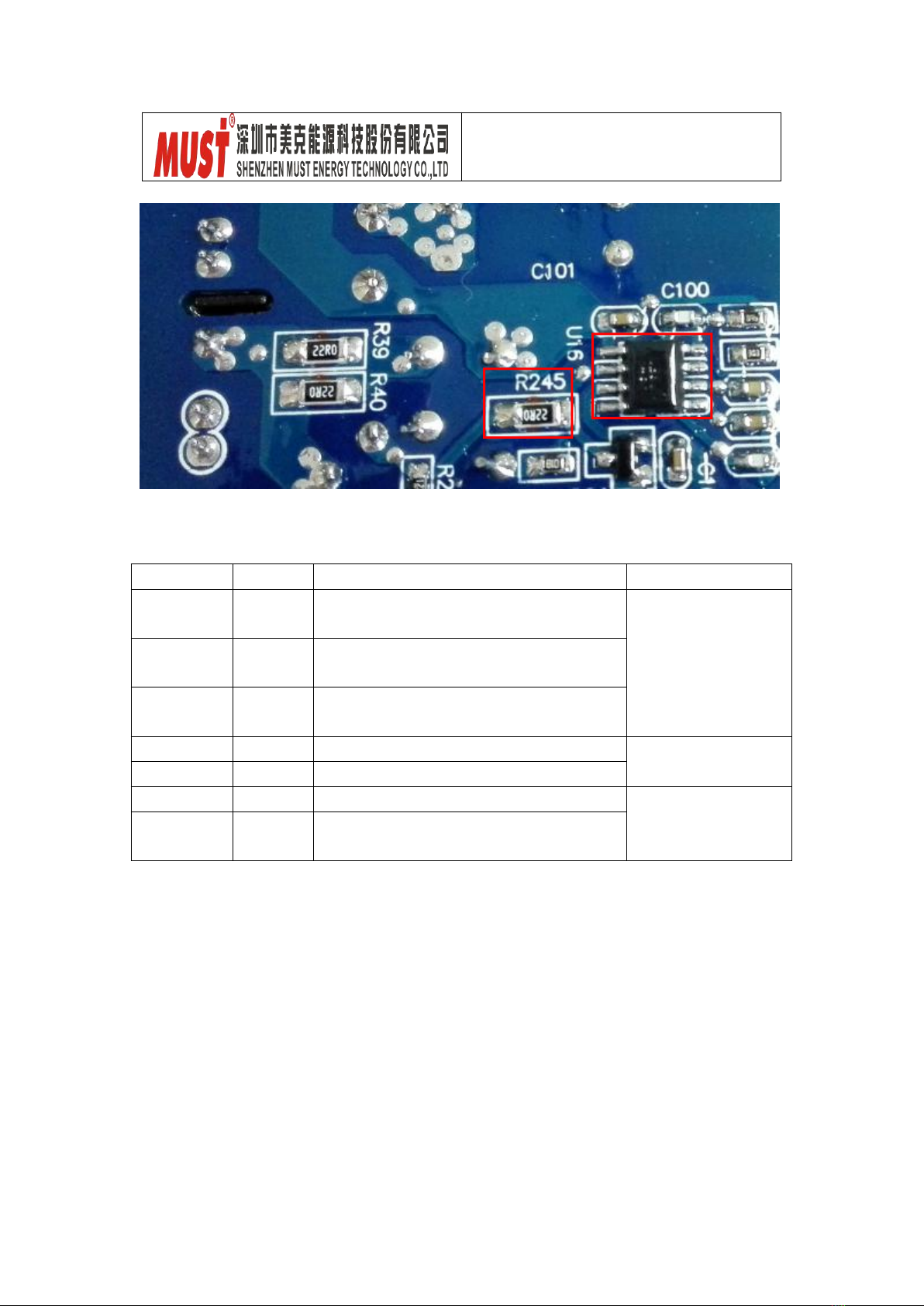
R245: 100-10022-00 (SMD Resistor CHIP TF 1/4W 22 F (1206))
Service Manual
PH1800 PLUS 4K/5K
- 18 -
Pin2
U16
Pin4
TX2: 240-00144-00 (Transformer TX 15:200:15 FER EEL16 PH18)
Positioning
Attribute
Reference Value
Failure Status
D65
Diode
+ to -:0.44V;
- to + :OL
Short Circuit
or Burnt
D73
Diode
+ to -:0.47V;
- to +:OL
Q6
Diode
SD:0.5V ;
DS: OL
R251
Resistor
0.8 ohm
Open Circuit
or Other Value
R245
Resistor
20 ohm
TX2
Resistor
Pin2-Pin4: 14 ohm
Short Circuit
or Burnt
U16
Resistor
Pin7-Pin5:42K ;
Pin6-Pin5:30K
This manual suits for next models
1
Table of contents
Other Must Inverter manuals

Must
Must EP18-5048 User manual

Must
Must pv3500 User manual

Must
Must PV1800 2K HM User manual

Must
Must pv3500 User manual

Must
Must PV1100 PLUS 1200VA User manual

Must
Must PV1800 2K HM User manual

Must
Must PV3000 PK User manual

Must
Must PH5000-T Series User manual

Must
Must PH30 Series User manual

Must
Must PV18 MPPT 3 KW User manual


Popular Inverter manuals by other brands


ZIEHL-ABEGG
ZIEHL-ABEGG ZA dyn 4C Original operating instructions

Sungrow
Sungrow SC50HV Quick installation guide

THOR
THOR TH225 instruction manual

Agilent Technologies
Agilent Technologies E4428C Configuration guide

Fischer Panda
Fischer Panda AGT 4000 PVMV-N Handbook

Enerdrive
Enerdrive ePOWER 300W: ePOWER 500W owner's guide


