Shinkawa VM-5 User manual

MANUAL NO. 29506E3.5
Published in Jun.1996
Revised in Jun.2008
VM-5 SERIES MONITOR
MODEL VM-5G SINGLE UNIT INSTRUMENT RACK
INSTRUCTION MANUAL

FOREWORD VM-5G
i
For safe operation.....
Thank you for using our VM-5 Series Monitor. SHINKAWA Sensor Technology applies strict quality control
and inspections to ensure the high reliability of its products.
This instruction manual contains descriptive information, specifications, and operating, setting, and adjusting
procedures.
Please study the contents of this manual and related manuals thoroughly before installing or operating the
equipment, and keep it handy for future reference.
"Safety Conventions"
Please thoroughly study the following section entitled "Safety Conventions" before operating the
equipment.
The safety symbols explained in this section are placed outside the left margin next to the text to which they
apply.
This unit is designed for use by specialists or persons thoroughly familiar with the field.
Make sure that the end user receives the Instruction Manual delivered with this unit.
Before use.....
When the unit is received, inspect it for damage suffered in transport and check
whether it is the item you ordered. In the unlikely event that it was damaged in transport
or does not function according to specifications, please contact the SHINKAWA Office
or dealer nearest you.
Store the unit under the ambient conditions given in the specification.
Avoid places where it is exposed to high humidity or corrosive gases.

SAFETY CONVENTIONS VM-5G
ii
Make it a rule to follow the instructions given in this manual.
This manual contains important information designed to prevent personal injury and property damage, and
ensure safe operation of the equipment.
Familiarize yourself with the signs and symbols explained below before proceeding to read the manual, and
observe the instructions given.
■Explanation of signs
Symbols Explanation
WARNING Indicates a potentially hazardous situation which, if not avoided, could result in death
or serious injury.
CAUTION Indicates a potentially hazardous situation which, if not avoided, may result in minor
or moderate injury. It may also be used to permit for property-damage-only accidents.
◊"Serious injury" refers to such injuries as loss of eyesight, injuries, burns (due to heat or cold), electric
shock, fractures, and poisoning, that have permanent aftereffects and require hospitalization or long-term
outpatient treatment.
◊"Moderate or minor injury" refers to such injuries as burns and electric shock that do not require
hospitalization or long-term outpatient treatment. "Property-damage-only accidents" refers to
consequential damage related to destruction of property and damage to the equipment.
■Explanation of symbols
Symbols Explanation
Indicates a prohibited action.
Details are given in the text next to the symbol.
Indicates a mandatory action.
Details are given in the text next to the symbol.

SAFETY CONVENTIONS VM-5G
iii
To ensure safe use of this equipment, strictly observe the safety precautions provided in this manual, as well
as installation methods and methods of use stipulated by laws and regulations. SHINKAWA Sensor
Technology will not be liable for damage, etc. due to methods of use contravening to the instructions provided
here.
■Safe use
WARNING
Make sure to ground.
May cause electric shock or malfunction.
Make sure to turn the power off before any wiring work.
Will cause electric shock.
CAUTION
Make sure that the power supply connected to the power supply input
terminals has the specified voltage and frequency.
Will cause damage and malfunction of the instrument.
A printed circuit board and electronic products may receive damage with
the static electricity of a human body.
Touch the metal part once and discharge your static electricity before
dealing with it.
Will cause damage and malfunction of the instrument.
Do not touch parts and soldered surfaces of the instrument rack.
Will cause damage and malfunction of the instrument.
The instrument rack is a precision instrument.
Take care not to expose it to excessive shock or vibration.
Do not change the parameter settings during operation.
May cause unexpected alarm output.
Do not measure insulation resistance and dielectric strength other than
those at places specified.
Will cause damage to the instrument.
Do not touch the surface of the instrument rack in the case of the high
environment temperature use, since the surface temperature of the rack
may be higher than the environment temperature by 10 to 20°C.
Do not remodel this monitor unit without permission.
Otherwise the guarantee can not be made.
PROHIBITION
Connect earth wire
MANDATORY
MANDATORY
PROHIBITION
PROHIBITION
PROHIBITION
PROHIBITION
PROHIBITION
PROHIBITION

SAFETY CONVENTIONS VM-5G
iv
■EMC(Electro-magnetic compatibility)
The EMC of each VM-5 Series monitor is evaluated by various noise tests.
However, its characteristics may vary with on environmental conditions such as the magnitude of noise,
ambient temperature, humidity and the arrangement of equipment.
For the above reason, when operating the monitor, please observe the following CAUTION.
CAUTION
The unit should be operated by specialists or personnel who have
knowledge of it.
When a shielded cable is used, the length of the unshielded cable section
should be less than 100mm.
For each relay used near this unit, devices related to this unit or signal
cables connecting the unit and these devices, install a surge killer.
Firmly tighten each screw used for mounting each unit. In additional,
always close the face plate for the unit, then fix it with knurled screws.
In order to prevent the system from its malfunction when the unit fails,
provide the systematic interlock function.
Do not wire input signal cables in parallel with control and power cables.
It is recommended that separated wire ducts be used for these cables.
Do not use any radio equipment near the unit.
■Noise filter
Noise transmitted through in each cable may be rejected to some extent by inserting a ferrite core in the cable
(note 1).
If the cable passes through noisy surroundings, it is recommended that such a noise prevention device is used.
(note 1) ZCAT3050-1330 : TDK
MANDATORY
MANDATORY
MANDATORY
MANDATORY
MANDATORY
PROHIBITION
PROHIBITION

TABLE OF CONTENTS VM-5G
v
1. GENERAL INFORMATION
--------------------------------------------------------------------------------------------------- 1
2. SPECIFICATIONS
--------------------------------------------------------------------------------------------------- 2
3. OUTLINE DRAWING
--------------------------------------------------------------------------------------------------- 3
4. INTERCONNECTION
4-1 POWER SUPPLY WIRING --------------------------------------------------------------- 4
4-2 WIRING OF EXTERNAL CONTACT INPUT ----------------------------------------- 5
4-3 WIRING OF RECORDER AND BUFFER OUTPUT -------------------------------- 6
4-4 ALARM OUTPUT WIRING ---------------------------------------------------------------- 7
5. DESCRIPTION OF PARTS
5-1 DESCRIPTION OF SIDE/REAR PARTS ---------------------------------------------- 8
5-2 DESCRIPTION OF PARTS --------------------------------------------------------------- 9
6. INSTALLATION
6-1 PANEL CUTOUT ---------------------------------------------------------------------------- 10
6-2 PANEL INSTALLATION ------------------------------------------------------------------- 11
7. UNIT INSTALLATION
7-1 REMOVAL OF MONITOR ---------------------------------------------------------------- 12
7-2 MOUNTING OF MONITOR --------------------------------------------------------------- 13
7-3 REMOVAL OF POWER SUPPLY UNIT ----------------------------------------------- 15
7-4 MOUNTING OF POWER SUPPLY UNIT --------------------------------------------- 16
8. MAINTENANCE
8-1 REPLACEMENT OF VM-5G POWER UNIT ----------------------------------------- 17

1. GENERAL INFORMATION VM-5G
-1-
OVERVIEW
The VM-5G is a single unit independent type instrument rack with a power supply for each VM-5
series monitor (except VM-5P Communication / Phase Marker Unit), 4-opint relay, SPDT(DAN.1,
DAN.2, ALE.1, ALE.2) and OK relay.
FEATURES
• Conforms to API St’d 670.
• Contact output (Danger / Alert alarm).
• Contact output (Input abnormal alarm).
• Can use variable voltage and frequency (85 to 264VAC / 48 to 64Hz) as power supply.
• Single unit independent type
• Carefully read both this manual and the manual for the VM-5 Series monitor unit to
be mounted in this rack.
• For INTERCONNECTION and MAINTENANCE proceed as described in the
instruction manuals for the VM-5 Monitor Unit used in combination with this
instrument rack.
•If megger test is made on the signal cable between transducer and monitor,
disconnect the cable from transducer and monitor.
Be sure to discharge the charged electric load before connecting the cable to the
transducer and monitor.
If this caution is not adhered to, the transducer and monitor could be damaged.
Mandatory
Mandatory
Caution

2. SPECIFICATIONS VM-5G
-2-
Power supply voltage Input Tropical
spec. CE marking *3
0 85 to 264VAC 1 CA Series,CV-86 *1
1 24VDC
2 110VDC
2 CV-85,CV-87 *2
VK,RD,FK,MS
VC,VM-11P,VM-21P
3 Input for VM-51
1CH:VK,FK
2CH:VK,FK
φ
I:VK,RD,FK
4 Input for VM-55
1CH:VK-202A,FK-202F
2CH:CV-86,CV-88
BEZEL
(OPTION)
Required(couple)
Not required
POWER OUTPUT FOR
TRANSDUCER
+24VDC, 4mA (input code:1)
-24VDC,20mA (input code:2)
1CH : -24VDC, 40mA 2CH : -24VDC, 20mA (input code:3)
1CH : -24VDC, 20mA 2CH : +24VDC, 4mA (input code:4)
EXTERNAL CONTACT
INPUT
(FROM REAR PANEL)
Contact for alarm reset (normally open)
Contact for sequence (normally open)
Contact type : Dry contact
INSULATION
RESISTANCE
Between power supply and GND : 100MΩor more at 500VDC
Between GND and alarm contact : 100MΩor more at 500VDC
DIELECTRIC STRENGTH
Between power supply and GND : 1500VAC, one minute
POWER
CONSUMPTION
VM-5G0 : 40VA or less
VM-5G1 : 30W or less
VM-5G2 : 40W or less
OTHERS
RELAY POINTS 5 points(DANGER1,ALERT1,DANGER2,ALERT2,OK)
TEMPERATURE
RANGE
Operating temperature : 0 to 65°C (32 to 149°F)
Storage temperature : -30 to +85°C (-22 to +185°F)
Relative humidity : 20 to 95% (noncondensing)
CONTACT RATING
(LOAD RESISTANCE)
250VAC,0.2A 30VDC,2A
CONTACT LIFE 100,000 times or more(rated load)
CONTACT METHOD SPDT(DAN.1,DAN.2,ALE.1,ALE.2,OK)5 points relay
MATERIAL AND FINISH Rack : SPCC Unichromate plating finish (black)
Rear plate : SPCC Unichromate plating finish (black)
Bezel : Aluminum Munsell N-1.0 (equiv.)
PROTECTIVE
CONSTRUCTION
Plastic sealed
MASS Rack : max.1.8kg
Bezel : max.0.2kg
Alarm contact operation
Monitor power ON
Monitor alarm relay mode Monitor power OFF Normal state Alarm state
NO contact NORMALLY DE-ENERGIZED OPEN OPEN CLOSE
NO contact NORMALLY ENERGIZED OPEN CLOSE OPEN
NC contact NORMALLY DE-ENERGIZED CLOSE CLOSE OPEN
NC contact NORMALLY ENERGIZED CLOSE OPEN CLOSE
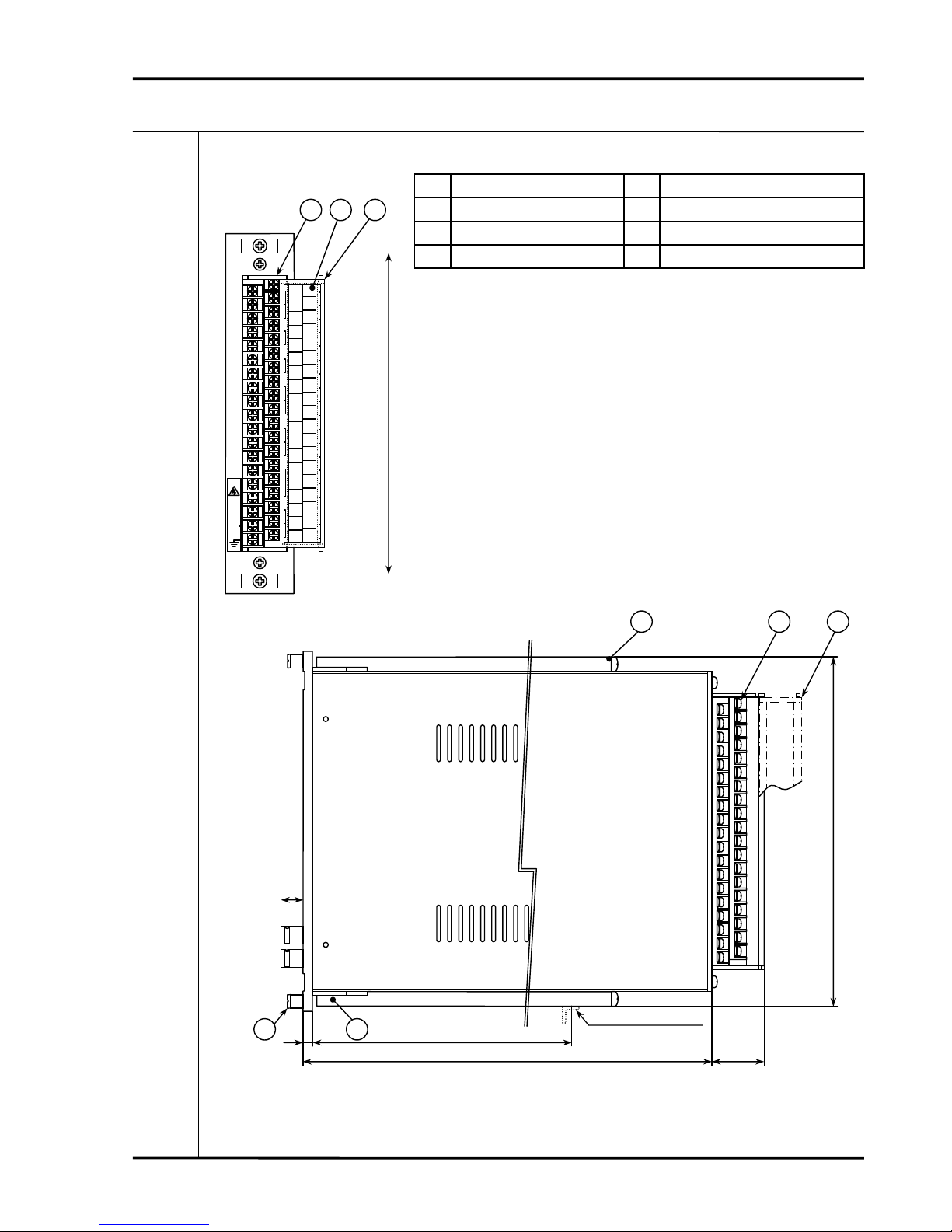
Note) Ventilation holes are drilled through the top, bottom and side faces of the instrument rack for natural
cooling. When mounting the instrument rack within the panel, do not close these ventilation holes. I
f
closed, the temperature in the rack may rise to shorten the service life of electronic parts used.
Do not place anything which interrupts ventilation within 200 mm from top and bottom faces of th
e
instrument rack.
Do not place the apparatus which generates heat under the instrument rack.
Be careful when installing the instrument rack in a bad-ventilated closed box (instrument panel).
It may cause shortening the life time of electronic parts because of marked rising in temperature of th
e
instrument rack in a bad-ventilated closed box which keeps the heat in.
Cool down inside the box with a cooling fan or the like.
Especially when installing in a small closed box, use the forced-air cooling apparatus like an electronic ai
r
conditioner.
/TRP/CEM
Ordering Information Standard Specifications
VM-5G -
Note) This code is applicable only to Model VM-5G.
Model Code / Additional Spec. Code( )
No entry if additional
spec. code is not specified.
Note) *1 2-wire transducer requiring a constant current power supply
(+24VDC, 4mA).
*2 3-wire transducer requiring a -24VDC power supply,
or any other transducer that does not cause power to be
supplied from the monitor to the transducer.
*3 Power supply is 0,2 : Can not select.
Standard Specifications
39516E4.3

3. OUTLINE DRAWING VM-5G
-3-
No. Name No. Name
1 Terminal block 4 Panel set screw
2 Terminal cover 5 Signal assignment table
3 Mounting bracket - ---
Finish Face plant : Munsell N-4.0 (equiv.)
Box, Flame : Unichromate plating finish (black)
Weight max. 1.8kg
The drawing shows an example of a typical VM-5 Monitor unit
mounted in the VM-5G0 Single Unit Instrument Rack.
Dimensions : mm
A1
IN
A2
COM
A3
PWR
A4
REC+
A5
REC-
A6
BUF
A7
COM
A8
NC
A9
DAN1
A10
NO
A11
NC
A12
ALE1
A13
NO
A14
NC
A15
OK
A16
NO
A17
L1
A18
L2
A19
F.G.
B2
COM
B3
PWR
B4
REC+
B5
REC-
B6
BUF
B7
COM
B8
NC
B9
DAN2
B10
NO
B11
NC
B12
ALE2
B13
NO
B14
SEQ
B15
COM
B16
P-5
B17
RES
B18
COM
B19
FLT
B1
IN
L1
L2
177
1 5 2
3 1 2
197
(28.5)
330.5
(200~250)
(5)
(12)
Support angle
Shore up a cabinet with the
support angle to be prepared
by customer.
34

4. INTERCONNECTION VM-5G
-4-
4-1 POWER SUPPLY WIRING
•Beware of electric shock from high-voltage parts.
• When using a DC power source, make especially sure not to reverse the polarities
as this will cause serious damage.
• Make sure to confirm that the power supply voltage matches that of the equipment.
• Use cables with AWG No.14 to No.18 gage (0.75 - 2mm2) stranded conductors for
wiring of the power supply input terminals.
•Make sure to ground the GND terminal.
Caution
Mandatory
Prohibition
Connect earth
wire
VM-5G1,2 Single Unit Instrument Rack
Input / output terminal block
A13
NO
A14
NC
A15
OK
A16
NO
A17
+24V
A18
0V
A19
FG
B13
NO
B14
SEQ
B15
COM
B16
P-S
B17
RES
B18
COM
B19
FLT
F.G
0V
+24V or
+110V
Power supply input
(24VDC or 110VDC)
VM-5G0 Single Unit Instrument Rack
Input / output terminal block
A13
NO
A14
NC
A15
OK
A16
NO
A17
L1
A18
L2
A19
FG
B13
NO
B14
SEQ
B15
COM
B16
P-S
B17
RES
B18
COM
B19
FLT
F.G
L2
L1
Power supply input
(85 to 264VAC)

4. INTERCONNECTION VM-5G
-5-
4-2 WIRING OF EXTERNAL CONTACT INPUT
• Beware of electric shock from high-voltage parts.
• Sequence function
Short between the SEQ and COM terminals to activate the sequence function.
• Reset function
Short between the RES and COM terminals to release any alarm under hold.
• Power sequence function sequence
Short between the P-S (power sequence) and COM terminals to cut off the
secondary (internal) power supply.
• Filter sequence function.
Short between the FLT and COM terminals to activate the seismic filter function.
• It is necessary to keep short circuit of the terminals for more than one (1) second to
operate these functions.
• Power sequence function should be applied only for short time (less than one (1)
minute) and emergency use such as the case of pulling out and inserting the monitor
unit.
If this function is used for long time over one (1) minute, monitor damage will result.
Warning
Caution
A8
NC
External reset
Contact input
VM-5G Single Unit Instrument Rack
Input / output terminal block
SEQ
COM
P-S
RES
COM
Power sequence
Contact input
Sequence circuit
Contact input
A9
DAN
A10
NO
A11
NC
A12
ALE
A13
NO
A14
NC
A15
OK
A16
NO
A17
L1
A18
L2
A19
FG
B8
NC
B9
DAN
B10
NO
B11
NC
B12
ALE
B13
NO
B14
SEQ
B15
COM
B16
P-S
B17
RES
B18
COM
B19
FLT
Filter sequence
Contact input
FLT

4. INTERCONNECTION VM-5G
-6-
4-3 WIRING OF RECORDER AND BUFFER OUTPUT
• Make sure to insulate the buffer output against earth.
If not insulated, a 2-point earth system results, which may cause noise interference.
• In the case that VM-5G is used with VM-5C eccentricity monitor unit, the connection
wiring of the recorder output and buffer output shall be as the following table.
And in the case that VM-5G is used with the monitor unit with the one (1) recorder
output, the recorder output shall be output from the CH1 recorder output terminal.
Monitor unit CH1
Recorder output
CH1
Buffer output
CH2
Recorder output
CH2
Buffer output
VM-5C
Eccentricity monitor Eccentricity pk-pk CH1 input
(Phase marker) Direct CH2 input
(Eccentricity)
Mandatory
A1
IN
A2
COM
A3
PWR
A4
REC+
A5
REC-
A6
BUF
A7
COM
A8
NC
B1
IN
B2
B3
PWR
B4
REC+
B5
REC-
B6
BUF
B7
COM
B8
REC+(CH2)
REC-(CH2)
REC+(CH1)
REC-(CH1)
BUF (CH1)
COM
BUF (CH2)
COM
VM-5G Single Unit Instrument Rack
Input / output terminal block
CH2
Recorder output
CH1
Recorder output
CH1
Buffer output
CH2
Buffer output

4. INTERCONNECTION VM-5G
-7-
4-4 ALARM OUTPUT WIRING
• Beware of electric shock from high-voltage parts.
• Do not exceed the allowable contact capacity of the alarm contacts.
• In the case that the alarm output type of the thrust monitor, the differential expansion
monitor etc. is CH1 : 4 points (H-DANGER, H-ALERT, L-ALERT, L-DANGER),
L-ALERT, L-DANGER shall be output respectively from CH2 ALERT, CH2
DANGER.
• In the case that the alarm output type is voting logic such as AND or OR output of
CH1/CH2, CH1 ALERT terminal (SR1 for VM-5S, VM-5R) and CH1 DANGER
terminal (SR2 for VM-5S, VM-5R) shall be used for the connection.
Warning
Mandatory
A8
NC
A9
DAN
A10
NO
A11
NC
A12
ALE
A13
NO
A14
NC
A15
OK
A16
NO
A17
L1
A18
L2
A19
FG
B8
NC
B9
DAN
B10
NO
B11
NC
B12
ALE
B13
NO
B14
SEQ
B15
COM
B16
P-S
B17
RES
B18
COM
B19
FLT
A1
IN
A2
COM
A3
PWR
A4
REC+
A5
REC-
A6
BUF
A7
COM
B1
IN
B2
COM
B3
PWR
B4
REC+
B5
REC-
B6
BUF
B7
COM
A8
NC
A9
DAN
A10
NO
A11
NC
A12
ALE
A13
NO
B8
NC
B9
DAN
B10
NO
B11
NC
B12
ALE
B13
NO
CH2
DANGER
alarm output
OK
alarm output
NC contact
output
NO contact
out
p
ut
CH2
ALERT
alarm output
CH1
DANGER
alarm output
CH1
ALERT
alarm output
(VM-5S,R SR4)
(VM-5S,R SR3)
(VM-5S,R SR2)
(VM-5S,R SR1)
VM-5S
,
R
NC contact
output
NO contact
out
p
ut
NC contact
output
NO contact
out
p
ut
NC contact
output
NO contact
out
p
ut
NC contact
output
NO contact
out
p
ut
VM-5G Single Unit Instrument Rack
Input / output terminal block

5. DESCRIPTION OF PARTS VM-5G
-8-
5-1 DESCRIPTION OF SIDE / REAR PARTS
No. Name No. Name
1 Terminal block 4 Panel set screw
2 Terminal cover 5 Signal assignment table
3 Mounting bracket - ---
The drawing shows an example of a typical VM-5 Monitor unit
mounted in the VM-5G0 Single Unit Instrument Rack.
A1
IN
A2
COM
A3
PWR
A4
REC+
A5
REC-
A6
BUF
A7
COM
A8
NC
A9
DAN1
A10
NO
A11
NC
A12
ALE1
A13
NO
A14
NC
A15
OK
A16
NO
A17
L1
A18
L2
A19
F.G.
B2
COM
B3
PWR
B4
REC+
B5
REC-
B6
BUF
B7
COM
B8
NC
B9
DAN2
B10
NO
B11
NC
B12
ALE2
B13
NO
B14
SEQ
B15
COM
B16
P-5
B17
RES
B18
COM
B19
FLT
B1
IN
L1
L2
1 5 2
3 1 2
Support angle
Shore up a cabinet with the
support angle to be prepared
by customer.
34

5. DESCRIPTION OF PARTS VM-5G
-9-
5-2 DESCRIPTION OF PARTS
1 Terminal block
• For connection of the input transducers.
• Provides analog signals for recorder output.
• Provides monitor output through a buffer output terminal.
• Provides alarm contact output (DAN.1, DAN.2, ALE.1, ALE2)
(Speed relay output SR1, SR2, SR3, SR4 for the VM-5S Dual Tachometer and VM-5R
Tachometer.)
• Provides OK alarm contact output.
• Power supply input
• For external contact input (Sequence function, Reset function, Power sequence function)
2 Terminal cover
3 Mounting bracket
For fixing the instrument rack on the instrument panel.
4 Panel set screw
For fixing the monitor unit in the instrument rack.
5 Signal assignment table
Lists the signals assigned to the input / output terminals.
6 Bezel

6. INSTALLATION VM-5G
-10-
6-1 PANEL CUTOUT
A : Dimension(mm)
With bezel 38n+(n-1)×0.5+12
Without bezel 38n+(n-1)×0.5+2
n : Number of monitors to be mounted (≤20)
183
A
199
38n+(n-1)×0.2
38n+(n-1)×0.2+20

6. INSTALLATION VM-5G
-11-
6-2 PANEL INSTALLATION
• Ventilation holes are drilled through the top, bottom and side faces of the instrument
rack for natural cooling. When mounting the instrument rack within the panel, do not
close these ventilation holes. If closed, the temperature in the rack may rise to
shorten the service life of electronic parts used.
Do not place anything which interrupts ventilation within 200 mm from top and
bottom faces of the instrument rack.
Do not place the apparatus which generates heat under the instrument rack.
• Be careful when installing the instrument rack in a bad-ventilated closed box
(instrument panel).
It may cause shortening the life time of electronic parts because of marked rising in
temperature of the instrument rack in a bad-ventilated closed box which keeps the
heat in.
Cool down inside the box with a cooling fan or the like.
Especially when installing in a small closed box, use the forced-air cooling apparatus
like an electronic air conditioner.
(1) Insert the instrument rack from the front of the instrument panel.
(2) Insert 1 into the holes at the top and bottom of the instrument rack and slide it toward the
instrument panel.
(3) Insert 2 into the rear holes at the top and bottom of the instrument rack.
(4) Screw 3 into 2 and push 1 into the instrument panel.
• Avoid applying excessive force to the screws as this may deform the mounting
bracket.
INSTRUMENT PANEL(REAR)
Support angle to be
prepared by customer.
VM-5G SINGLE UNIT
INSTRUMENT RACK
Mandatory
Prohibition
Prohibition

7. UNIT INSTALLATION VM-5G
-12-
7-1 UNIT INSTALLATION
• Make sure to turn off the power.
• Failure to turn off the power before pulling the monitor unit out of the instrument rack
will result in serious damage and accidents.
1) Evenly loosen the knurled screw at the top and bottom of face plate.
• Tighten the screw by hand. Do not use any tools.
2) Pull out the monitor unit.
• Make sure not to touch the chassis.
Mandatory
Caution
Prohibition
Prohibition

7. UNIT INSTALLATION VM-5G
-13-
7-2 MOUNTING OF MONITOR
• Make sure to turn off the power.
• Failure to turn off the power before pulling the monitor unit out of the instrument rack
will result in serious damage and accidents.
1) Align the monitor chassis with the grooves in the top and bottom of the instrument rack and
push it into the rack.
• Make sure not to touch the chassis.
2) Next open the face plate sideways and insert the unit card located behind it firmly into the
connector.
Mandatory
Caution
Prohibition

7. UNIT INSTALLATION VM-5G
-14-
3) Close the face plate.
(When doing so, make sure to accommodate the flat cable in the space between the chassis and
the frame.)
4) Evenly tighten the knurled screws at the top and bottom of face plate.
• Tighten the screw by hand. Do not use any tools.
Prohibition
Other manuals for VM-5
2
Table of contents