Issued : Dec. 2016
Revised : Apr. 2022
*
1. Things to prepare before using this device:
Four M6 screws or four M6 bolts are required to install the
converter.
For the feeler gauge, a 20% of F.S. pitch (for 6-point adjustment)
or a 10% of F.S. pitch (for 11-point adjustment) is required to
adjust the device.
Since the accuracy of the feeler gauge to be used depends on the
measurement accuracy, use a gauge which matches the required
accuracy.
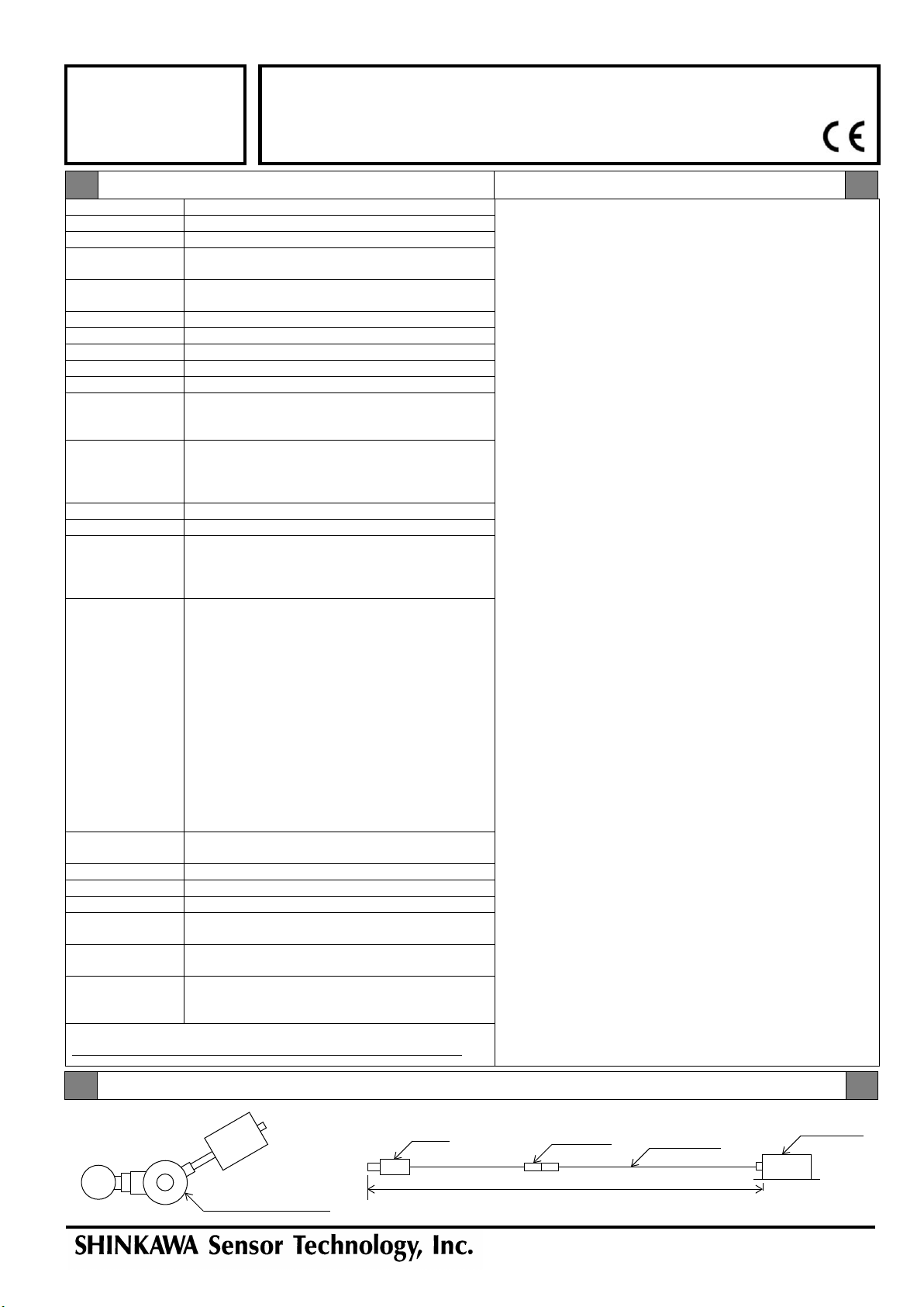
2. Configuration
Before connecting the sensor, extension cable, and converter,
make sure to match the serial numbers indicated on the converter
name plate or inspection test report.
Having the wrong combination of serial numbers may result in
specifications not being met.
When shipping sensor, extension cable or converter alone, we
have confirmed the operation in combination with our standard
equipment.
Before use, please calibrate the converter with the combination of
the sensor, extension cable and converter that are actually used.
Please refer to the instruction manual for the calibration method of
the converter.
The temperature characteristics (temperature drift) of the sensor,
extension cable or converter when shipped alone are as follows.
Sensor: ± 1.5% of F.S. (typical),
Extension cable: ± 2.2% of F.S. (typical),
Converter: ± 2.2% of F.S. (typical).
In case of ordering the extension cable alone, please inform us
the sensor range information to be used in combination.
3. Megger testing of the signal transmission cables that connect to the
instrumentation
After you perform a megger test on the signal transmission cable,
make sure to discharge the electrical charge before connecting
the cable to the converter.
Connecting the cable to the converter or the instrumentation while
on a charged state may cause a failure
4. Sensor installation location
Do not use the device outdoors where the sensor can be subject
to rain water.
Doing so may cause deterioration of the insulation and alter the
sensitivity of the sensor.
*
*
Thickness
0.0 mm - 10.0 mm (actual gap: 0.8 mm - 10.8 mm)
0.8 mm
±0.5% of F.S. (for 6-point or 11-point adjustment)
5-digit, 7-segment LED (orange)
4-digit thickness display (unit: mm), 1-digit code
Display LED Power (red)
Meas. (green)
Teach (green)
range
(Connector part: -25°C to +85°C)
Extension cable: -25°C to +85°C
Temperature
characteristics Sensor: ±1.5% of F.S.
Condition gap: 50% of the thickness measurement range,
Target: Chilled steel (flat),
Temperature:+25°C is the normal temperature.
Range is 0°C to +100°C
Extension cable: ±1.5% of F.S.
Condition gap: 50% of the thickness measurement range,
Target: Chilled steel (flat),
Temperature:+25°C is the normal temperature.
Range is 0°C to +80°C
Converter: ±1.5% of F.S.
Condition gap: 50% of the thickness measurement range,
Target: Chilled steel (flat),
Temperature:+25°C is the normal temperature.
20% to 95% RH (non-condensing, non-immersing)
+24 VDC ±10%, Ripple (p-p) 10% or lower
Terminal block screw size: M3
insulation resistance
Between the power supply terminal and the FG terminal:
20 MΩor higher on 500 VDC
withstand voltage Between the power supply terminal and the FG terminal:
60 Hz on 500 VAC within 1 minute
Extension cable:Approx. 1.3 kg
Converter: Approx. 1.0 kg
Other
FK Series
Transducer
Specifications
VN Series
Specifications
VND Thickness Measurement Converter (10 mm range)
Configuration
System cable length: 6.5 m
NoticeSpecifications


