Electric cables must be disconnected from power during installation work.
Sockets P8, P2 and P3 are connected respectively to the ACS RFID key reader and to the activation pushbuttons.
Power the pcb of the module through P5 socket: provide +24V or +12V between pin 3 (+ Vdc) and pin 5 (GND).
The output activation signals will be available from the same P5 socket, between pin 2 and pin 6 (TTL Open Collector
mode) for User A and User B respectively.
If the A / B machine(s) to be activated are not equipped with an interface relay or pcb, please make use of the Alberici
Servo-realy p.c. board (see next section 3.3).
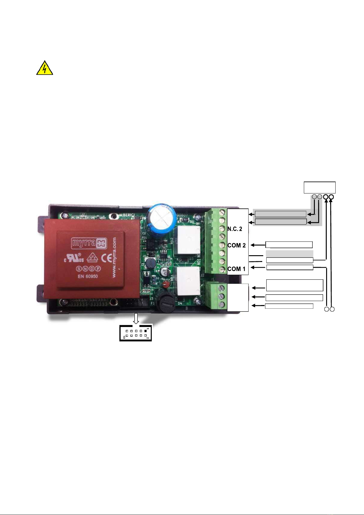
3.3 Servo-relay pcb
The Servo-relay pcb is available for 230V AC, or 24V AC / DC, or 12V DC input power. It supplies +12V between the pins 1 (GND) and
2 (+) of the 10-pole connector J3 (2x5). Please specify at the time of order which power supply is needed: the Servo-relay pcb will then
be set up according to the desired power supply.
3.3.1 Connections to start the equipment by relay transmission of power supply:
Service Line 1 (Pushbutton A): from power supply, connect one end of service Line 1 straight to the relevant actuator (i.e.
electrical motor, solenoid, a.s.o.). Connect the other end to pin 1 (COM 1) of J2 connector.
If operation mode is “normally open”, take the switching wire to the 1 actuator from pin 2 (N.O. 1). These wires must be able
to sustain 10 Amps current draw.
If operation mode must be “normally closed”, take the switching wire to the actuator from pin 3 (N.C. 1). If the actuator
works by d.c., take care to connect properly positive and negative poles!
Service Line 2 (Pushbutton B): from power supply, connect one end of service Line 2 straight to the relevant actuator (i.e.
electrical motor, solenoid, a.s.o.). Connect the other end to pin 4 (COM 2) of J2 connector.
If operation mode is “normally open”, take the switching wire to the 2 actuator from pin 5 (N.O. 2). These wires must be able
to sustain 10 Amps current draw.
If operation mode must be “normally closed”, take the switching wire to the actuator from pin 6 (N.C. 2).
It is possible to disable coin acceptance in any of the following two ways:
Electronically - connector J2: provide any Vdc (+) or Vac to pin 7, and respectively 0Vdc (-) or Neutral Vac to pin 8.
Mechanically - move to OFF the dip-switches located on the coin acceptor. Move them back to ON when coin
acceptance must be restored.
To/from P5 connector of the
Active One display board
EQUIPMENT:
230Vac, or
or +24Vdc, or
OUT 1: LINE 2, N.O.
OUT 1: LINE 2, N.C.
IN 2: C2 LINE 2
DISABLE: Vac N or -Vdc
POWER IN: N (ac) or - (dc)
- / N
GND
POWER IN: 230Vac, or
24Vac, or +24Vdc, or +12Vdc
INH –
INH +
N.O. 2
N.C. 1
N.O. 1