ShopBot Desktop MAX User manual
© Copyright May, 2022 ShopBot Tools, Inc.
page 1
Desktop MAX Automatic Tool
Changer (ATC) User Manual

Desktop MAX Automatic Tool Changer (ATC) User Manual SBG00358
© Copyright May, 2022 ShopBot Tools, Inc.
page 2
Table of Contents
Introduction...............................................................................................................................................3
ATC Software Setup and Tool Calibration.................................................................................................4
Install the ATC Software........................................................................................................................4
ShopBot Setup (TS)..................................................................................................................................5
Software Inputs and Outputs Check ..........................................................................................................9
Inputs.................................................................................................................................................... 9
Outputs............................................................................................................................................... 10
Basic Function Check.......................................................................................................................... 10
Additional function checks................................................................................................................... 11
Z Zero Plate.................................................................................................................................... 11
Fixed Z Zero Plate........................................................................................................................... 11
Tool Draw Bar................................................................................................................................. 11
Calibrating the ATC................................................................................................................................. 12
Calibration Routine.............................................................................................................................. 12
Set Fixed Z-Zero Plate Location...................................................................................................... 14
Setup Tool Holders.......................................................................................................................... 15
Change Tools (C1).......................................................................................................................... 17
Zero Tools in Rack (CN72) (Daily Operation)................................................................................... 17
Get Plate Offset (CN73)................................................................................................................... 18
Zero to Various Z Heights (C2) (Daily Operation)............................................................................. 19
Regularly Used ATC Files....................................................................................................................... 19
Create a Tool Change File ...................................................................................................................... 20
Spindle Warmup Routine (C5)................................................................................................................. 21
Run the File ............................................................................................................................................ 21
Troubleshooting...................................................................................................................................... 22

Desktop MAX Automatic Tool Changer (ATC) User Manual SBG00358
© Copyright May, 2022 ShopBot Tools, Inc.
page 3
Introduction
The ShopBot Automatic Tool Changer (ATC) automates the bit changing process during projects that require
multiple tool changes. The ATC reduces the time a project must remain on the machine by automatically
changing bits between cuts, thus eliminating the need to change and calibrate tools by hand.
The ATC system includes:
A 1HP Teknomotor spindle
Filter/regulator with low pressure switch
Six-position tool bar
Magnetically removable dust skirt
ATC interface board
The 1HP Teknomotor spindle assembly is fan-cooled. The ATC requires 4 scfm at 90 psi of clean, dry, un-
oiled compressed air. PORTABLE AIR COMPRESSORS ARE NOT RECOMMENDED, as they can have
trouble maintaining this pressure reliably and have a reduced service life.
It is not recommended to leave a tool holder in the ATC spindle when not using the machine. When you are
done using the machine all tool holders should be removed and stored in the tool rack at the rear of the tool.
Using the software to change to tool #0 (explained on page 17) will accomplish this.
Connecting the Pneumatics
Locate the filter/regulator included with your tool. Inside the bag will be a mounting bracket and two
M5x12mm Button Head Screws. First, attach the mounting bracket to the rear of the tool on the corner
opposite the red power switch. Remove the plastic nut from the regulator and drop the regulator into the
bracket and thread the nut onto the regulator to lock it in place. Pull the blue main pneumatics hose from
under the tool and insert it into the orange quick-connect fitting. Plug your shop’s air-line into the fitting on the
left side of the filter.
Desktop MAX Automatic Tool Changer (ATC) User Manual SBG00358
© Copyright May, 2022 ShopBot Tools, Inc.
page 4
ATC Software Setup and Tool Calibration
This portion of the installation covers the software setup and tool calibration.
Install the ATC Software
Download the latest ShopBot control software from the ShopBot website:
http://www.shopbottools.com/mSupport/controlsoftware.htm
If an earlier version of the ShopBot control software is present, uninstall the software and install the most
recent version. Refer to “Uninstall/Reinstall ShopBot and VCarve Software”
at http://www.shopbottools.com/ShopBotDocs/software.htm
Note: If there are personal files within the “SbParts” folder, be sure to rename or move this folder so the files
are not lost.

Desktop MAX Automatic Tool Changer (ATC) User Manual SBG00358
© Copyright May, 2022 ShopBot Tools, Inc.
page 5
ShopBot Setup (TS)
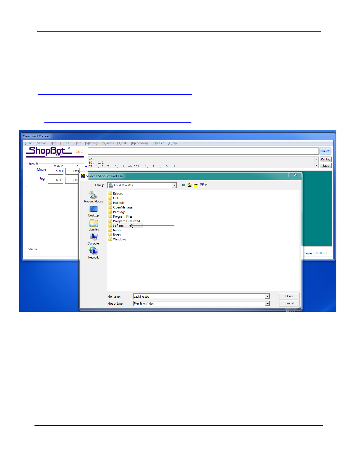
Type in “UR” or go to “Utilities” pull-down menu and select “Reset default Settings”. Select the file name that
correctly describes the machine (under the “PRS ShopBots” folder, then
ShopBot_PRSDesktopMAX3624.sbd)
Move the cutter to the location that is to be “0, 0” (the reference point for programming) on the
table. Open the ShopBot control software and open the “ShopBot Setup” file in the “Tools” drop-
down (TS). Read through the window and click “Next”. The second window is the “Tool Settings”.
(0,0)
Desktop MAX Automatic Tool Changer (ATC) User Manual SBG00358
© Copyright May, 2022 ShopBot Tools, Inc.
page 6
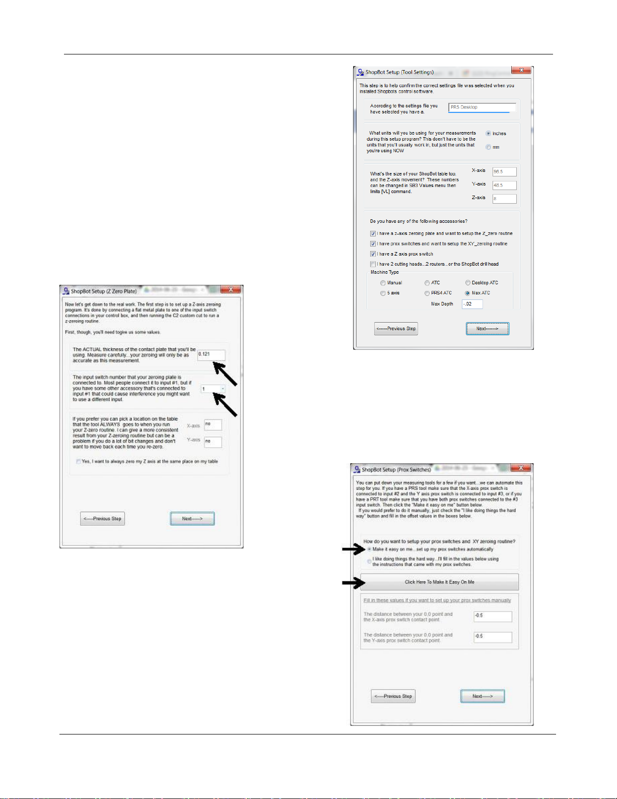
Go step-by-step through this window while verifying
information about the machine. Make sure that the check
boxes for the Z zero plate and proximity switches are checked at
the bottom of the window. Select the radio button marked
“MAX ATC”. Click “Next”.
In the “ShopBot Setup (Z Zero Plate)” screen, measure the
thickness of the plate and enter that value. Make sure the input
switch is set to “1”. DO NOT check the “Yes, I want to always zero
my Z axis at the same place on my table”. Click “Next”
.
At the “ShopBot Setup (Prox Switches)” screen, select
“Make it easy on me…” and click the “Click Here To Make It
Easy On Me” button to start the zeroing routine.

Desktop MAX Automatic Tool Changer (ATC) User Manual SBG00358
© Copyright May, 2022 ShopBot Tools, Inc.
page 7
The next screen is “X and Y axis zeroing setup”. Read this screen and click
“Run the prox switch setup routine”.
Follow the prompts from the pop-up screens. Select “Yes” to
open the keypad for any adjustment to the “0, 0” home
position, then click “OK”. The default home position is the
corner of the spoilboard near the machine’s natural “0,0”, but
you can set it wherever you want if you are using a specific
jig or fixture.
Move the machine to the zero point, and hit “ESC” to exit the keypad
mode.
Click “Yes” to zero out the X and Y axes and click “OK”.
Desktop MAX Automatic Tool Changer (ATC) User Manual SBG00358
© Copyright May, 2022 ShopBot Tools, Inc.
page 8
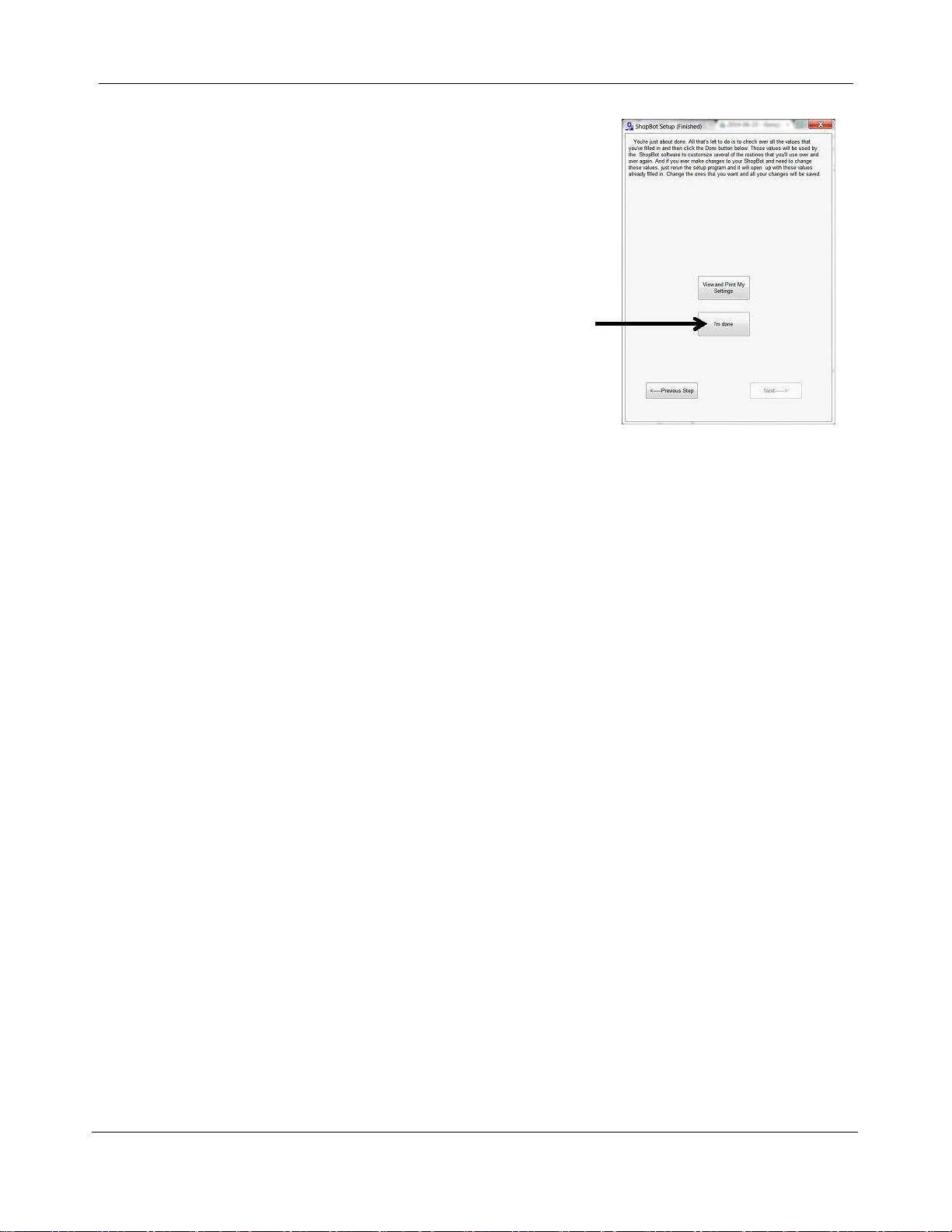
Read through the “ShopBot Setup (Finished)” window and click “I’m
done.”

Desktop MAX Automatic Tool Changer (ATC) User Manual SBG00358
© Copyright May, 2022 ShopBot Tools, Inc.
page 9
Software Inputs and Outputs Check
Ensure that all of the inputs and outputs are being recognized by the automatic tool changer (ATC) by
checking for each of the cases outlined in this section.
Inputs
Inputs are signals that the software receives from devices that cause the tool to have a specific reaction.
Input 1 –The Z zero plate and the fixed Z zero are connected to this input. When either of these
plates are connected to a ground, the circuit is closed and input “1” on the ShopBot position screen
lights up. The tool’s fixed z-zero plate does not require a grounding clip, however use of the
standard z-zero plate does.
Input 2 –NA
Input 3 –The X, Y, and Z-axis proximity switches are connected to this input. During normal
operation, the input “3” light will be off in the ShopBot position screen. If one of the proximity
switches passes the proximity targets, the light will turn on. Among other things, this feature will be
used for homing the X, Y, and Z positions and for limiting the safe table cutting boundaries.
Input 4 –This input is connected to the stop switch. When inactive, the switch allows for use of the
tool and when active, the connection is severed and the tool comes to a stop.
Input 5 –NA
Input 6 –Tool bar in extended position, ready to make tool change. Lights when tool bar is fully
extended.
Input 7 –Tool in spindle. Lights when tool holder is properly inserted into spindle and clamped.
Input 8 –Drawbar open. Lights during tool change when draw bar is open and tool holder can be
inserted or removed.
Desktop MAX Automatic Tool Changer (ATC) User Manual SBG00358
© Copyright May, 2022 ShopBot Tools, Inc.
page 10
Outputs
Outputs are signals that ShopBot software is sending to cause a desired action. Unused outputs can be
programed to activate other peripherals using an optional relay board.
Output 1 –Runs the spindle.
Output 2 –NA
Output 3 –NA
Output 4 –Turns on during machine operation (safety flashing screen). Required for spindle “on” signal.
Output 5 –NA
Output 6 - NA
Output 7 –Toggles the toolbar forward and backward. When output 7 is triggered, the toolbar should be
extended and ready for a tool change.
Output 8 - Toggles the spindle drawbar open /close (releases tool holders from spindle).
Caution: When the spindle is not spinning it is possible to drop the tools from the spindle if Output 8
is activated.
Basic Function Check
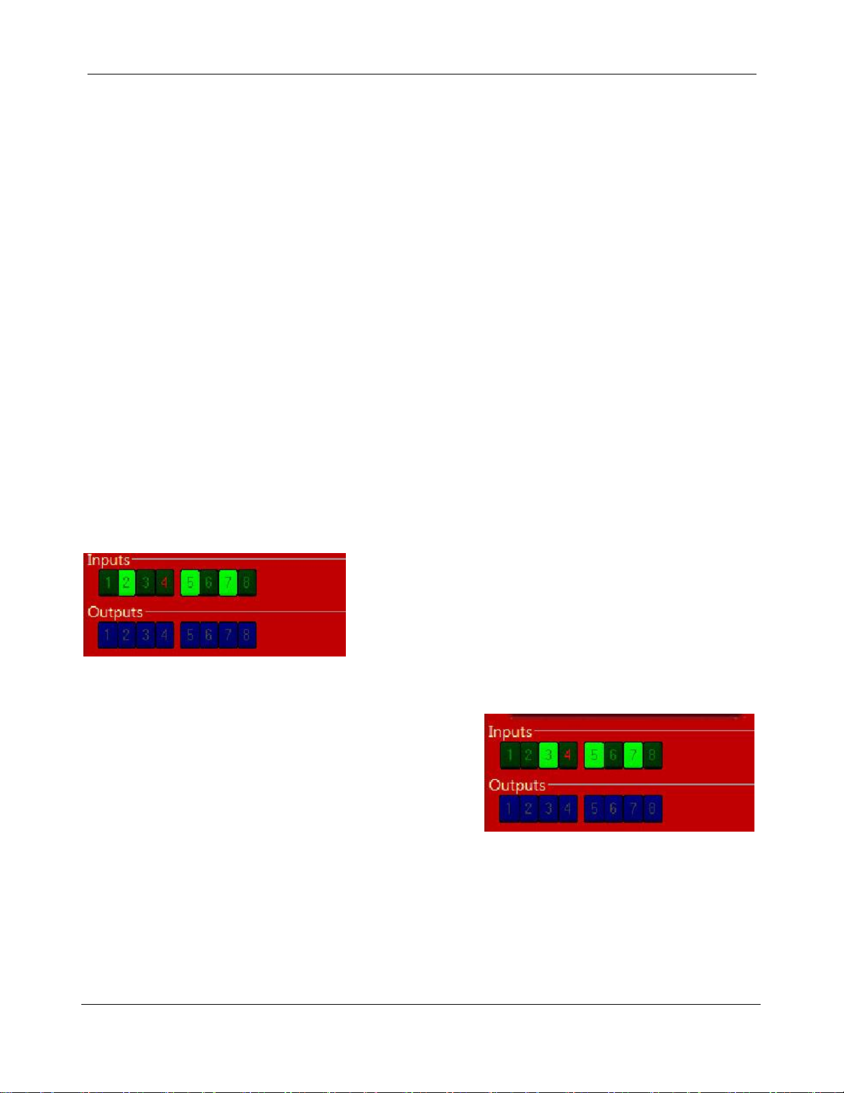
Check that all systems involved are working properly, starting with the proximity switches.
In keypad mode (K) move the X-axis into the proximity target
using the left arrow on the keypad. The proximity switch will
have a red LED lit until it comes across the proximity target,
when it will turn off. Moving off the top of the target should cause
the LED to come back on. This should also be evident in the
ShopBot position screen when looking at input “2”, the light will
turn from black (normally closed) to green (open).
In keypad mode (K), move the Y-axis into the proximity target
using the down arrow on the keypad. The proximity switch will
have a red LED lit until it comes across the proximity target,
when it will turn off. Moving off of the target should cause the
LED to come back on. This should also be evident in the
ShopBot position screen when looking at input “3”.
In keypad mode (K), move the Z-axis into the proximity target using “Page Up” on the keypad. The proximity
switch will have a red LED lit until it comes across the proximity target, when it will turn off. Moving off the top
of the target should cause the LED to come back on. This should also be evident in the ShopBot position
screen when looking at input “3”.

Desktop MAX Automatic Tool Changer (ATC) User Manual SBG00358
© Copyright May, 2022 ShopBot Tools, Inc.
page 11
Additional function checks
Z Zero Plate
To check the Z zero plate, insert the plug end of the Z zero plate cable into the socket located on
the gantry.
Touch the Z zero plate grounding clip to the Z zero plate and make sure that input “1” lights up
green on the position screen.
Fixed Z Zero Plate
To check the fixed Z zero plate, simply press down firmly on the
plate. Input “1” should light up green on the position screen while the
plate is pressed. The light should go off again when the plate is
released.
Tool Draw Bar
Make sure your compressed air supply is on for the
following checks.
Press the green button on the back of the gantry. While the
button is depressed the internal draw bar will open, allowing
the spindle to accept tools. While the draw bar is open, a
rush of air will be heard, and input “8” will be lit.
With the green button still
depressed, insert a tool holder into
the spindle and hold it there.
Release the green button. The
drawbar will close, capturing the
tool holder. Input “7” should light
up, and input “8” should turn off.
Desktop MAX Automatic Tool Changer (ATC) User Manual SBG00358
© Copyright May, 2022 ShopBot Tools, Inc.
page 12
Calibrating the ATC
Calibration Routine
If this is your first time setting up the machine, or you are setting it up on a new computer, the ShopBot
software needs to know the location of the tool holders. To run this routine, insert an empty tool holder (no
collet or bit, but can have collet nut) into the spindle using the green button on the rear of the gantry.
In the Shopbot 3 software, click on the large “Cut Part” button. Navigate to the C:\SbParts
folder\Custom\ATC on your computer and select the file named “ATC_DT_Calibrate”.
The machine will first home the X, Y and Z axes. The tool should end up at the home location previously
set in the ShopBot Setup routine. Next you will be prompted to extend the toolbar, press OK on this
prompt and the “spindle start” prompt. Then there will be a prompt on the screen asking you to use
the keypad to move the machine to the location of tool number 1. This is the tool closest to the
fixed Z-zero plate on the tool bar. Press OK to this prompt.
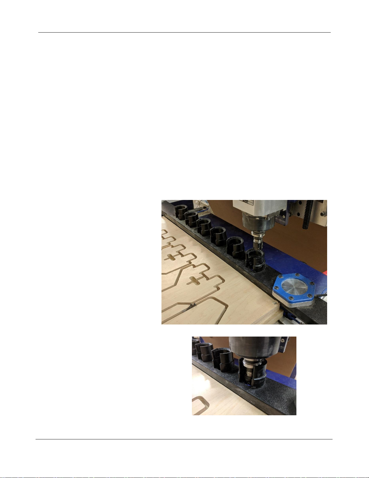
Using the keypad, move the machine
towards the first tool holder location
Once you get it close to the tool clip, press
the “Fixed” button in the keypad. This will
only allow the machine to move a small
distance with each keypress. Move the
toolholder down into the toolclip very
carefully, making sure it is not touching
the sides.

Desktop MAX Automatic Tool Changer (ATC) User Manual SBG00358
© Copyright May, 2022 ShopBot Tools, Inc.
page 13
While doing this, periodically spin the tool
holder with your fingers. It should spin
freely and not drag on the sides of the
toolclip.
With the bit still centered in the holder, continue lowering it
until it is almost touching the bottom of the holder. Or,
lower it until it no longer spins easily and then raise it back
up slightly until it does. Once the tool holder is in the
proper spot, press the ESCAPE key to exit the keypad.
Then press OK to the prompt that comes up on the screen.
The tool should then move the Z up and travel over to the
general location of the last tool clip on the rack. You’ll once
again be prompted to lower the tool holder into the tool
clip. Make any necessary adjustments in X and Y position
and lower the tool holder into the clip. Once you’ve got the
tool holder in place, exit the manual control pad to save
this position.
You’ll then be prompted to set the Fixed Z-Zero Plate Location. If this is your first set-up of the tool, answer
“yes” to this prompt to initiate the location routine. The following section of this manual will provide
instructions for running the z zero plate location routine; if you’re continuing on from the calibration routine,
the z zero plate location routine will start automatically. If you do not want to set up the fixed z zero plate
location at this time or need to adjust the location later, you can follow the steps in the following section to
run the routine without first calibrating the tool bar.
Make sure to remove the tool holder when this routine is done.

Desktop MAX Automatic Tool Changer (ATC) User Manual SBG00358
© Copyright May, 2022 ShopBot Tools, Inc.
page 14
Set Fixed Z-Zero Plate Location
If you haven’t already, run the homing routine (C3) to be sure everything is zeroed.
If routine does not start automatically after calibration load the file “ATC_FixZ_Plate.sbp” located in
“C:\SbParts\Custom\ATC\ ATC_FixZ_Plate.sbp”. This file will set the location of the fixed Z zero plate to set
a base zero height of the bits. This should only need to be run once during the setup procedures.
Click “OK” when the following prompt appears.
Use the keypad to move the spindle over the center of the fixed Z zero plate, as shown in the picture below.
Once satisfied with the positioning of the spindle, hit “ESC”. This will set the fixed Z zero plate location in the
X and Y. You do not need a tool holder inserted in the spindle to run this routine, although it may make it
easier to align the spindle with the Z-zero plate
Once the program is finished, press “ALT”+”7” again to retract the tool bar.
Desktop MAX Automatic Tool Changer (ATC) User Manual SBG00358
© Copyright May, 2022 ShopBot Tools, Inc.
page 15
Setup Tool Holders
Locate the tool holders, collet, collet nuts (shipped on the tool holders), and desired bits. Make sure that the
collets are sized for the shank diameters of the bits that will be installed.
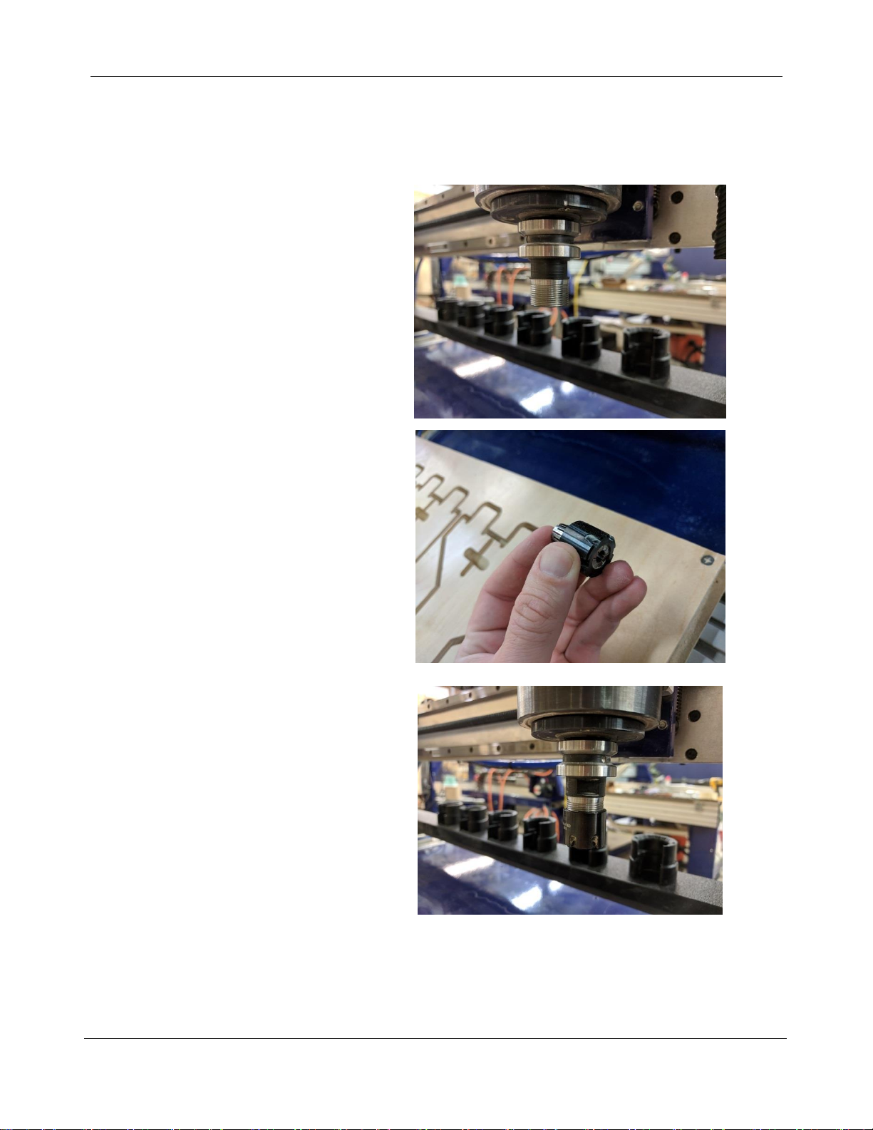
Remove the collet nut from a tool holder
and insert it into the spindle using the
green button on the back of the gantry.
Select the appropriate sized collet
for the bit you want to use, then
press it into the collet nut until it
snaps into place. It is VERY
IMPORTANT that the collet is
inserted into the collet nut before it
is installed in the tool holder. Failure
to install the collet into the nut may
cause damage to the tool holder.
Thread the collet nut onto the tool
holder that is in the spindle.
Desktop MAX Automatic Tool Changer (ATC) User Manual SBG00358
© Copyright May, 2022 ShopBot Tools, Inc.
page 16
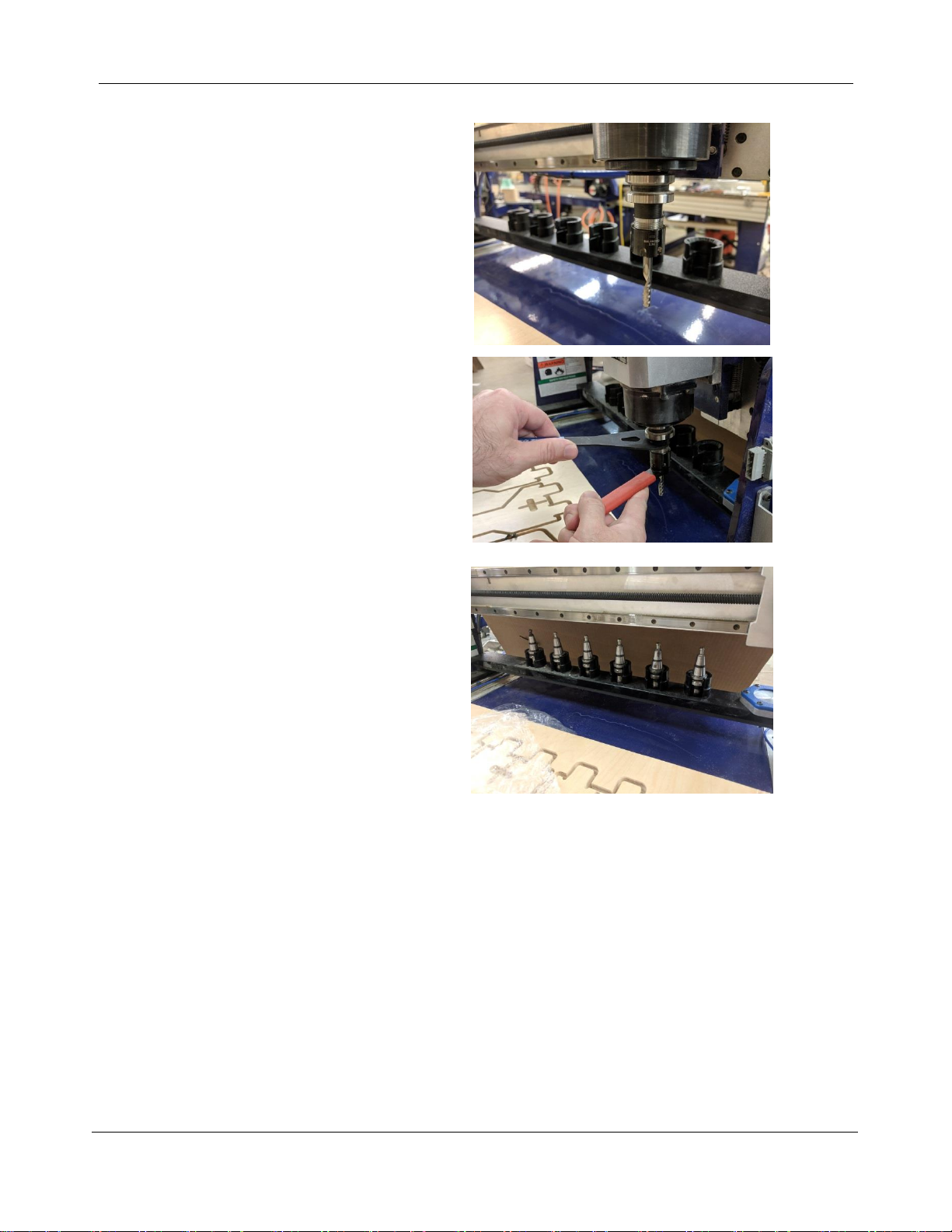
Insert the desired bit into the collet.
Tighten the collet nut to 42 ft/lbs with
the ER16 spanner wrench and 17mm
shaft wrench. Do not over-tighten.
Remove tool holder from spindle
using the green button and place it
into the tool clip that you would like
that bit assigned to. Repeat this
process for the other tool holders
and place them in the tool bar as
well. Do NOT leave a tool holder in
the spindle at this time.
Desktop MAX Automatic Tool Changer (ATC) User Manual SBG00358
© Copyright May, 2022 ShopBot Tools, Inc.
page 17
Change Tools (C1)
Insert bit into conical tool holder and place it in the desired tool holder location. Type C1 to run the custom
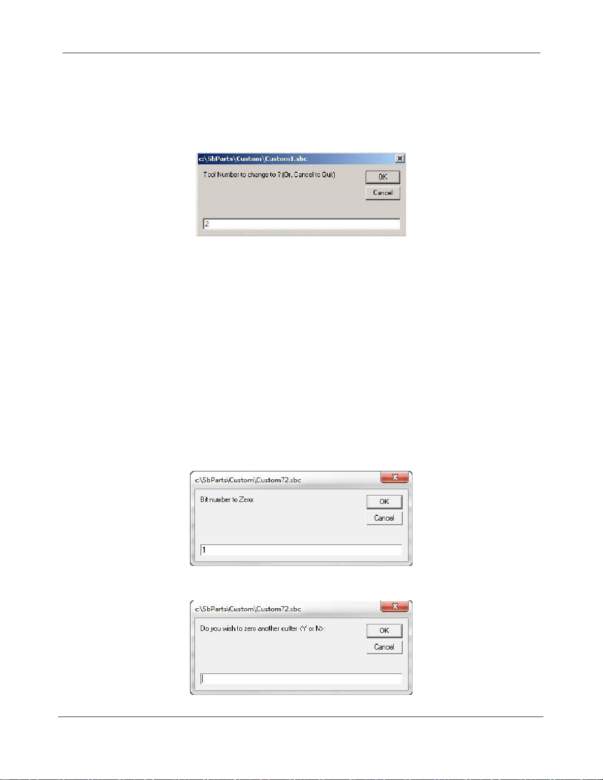
number 1 “Change Tools” routine. A screen will ask which tool should be selected. Once that tool is entered,
click “OK” and the ATC will drop off the current tool being held and select the desired tool. If there is currently
a tool in the spindle be sure that there is an empty tool clip in the correct location to receive it.
To check what tool the software thinks is in the spindle head, open
“C:\Sbparts\Custom\ATC_Local_Data\ATC_tool_variables.sbc”.
Look at line #3, &ToolIn= (Current tool) will show the tool last changed to.
Zero Tools in Rack (CN72) (Daily Operation)
This step will zero each tool in the rack to ensure that bits of different lengths will all cut to the same depth. It
is good practice to run this full routine (for all bits) at the beginning of each work period. If a new bit is added
to the rack (or an existing bit is replaced), use this routine to calibrate it to the other bits in the rack.
Ensure that there is no tool holder in the spindle. Run the homing routine (C3). A screen will open confirming
that tool #0 (empty spindle) is correct. Press “OK” to dismiss this prompt after confirming the spindle is
empty.
Type “CN72” (custom number 72), to run the ATC zero tools in rack file.
Enter the number of the bit to measure and then click “OK”. The tool will move to the fixed z-zero plate and
plunge until it makes contact with the plate)
If more bits need to be zeroed, answer “YES”. If not, then type “N”. Click “OK” to continue.
Desktop MAX Automatic Tool Changer (ATC) User Manual SBG00358
© Copyright May, 2022 ShopBot Tools, Inc.
page 18
Get Plate Offset (CN73)
This routine will establish where the C3 (XYZ zero) routine will set the Z zero level. Normally this is at the
table bed. This routine needs to be run whenever the location of the table bed has changed, such as after re-
surfacing the spoilboard. If a tool is not loaded in the spindle, select one before running this routine. Any tool
can be used as they have all been zeroed to the fixed plate. Type “CN73” (custom number 73) in the
ShopBot control software to run the ATC get plate offset file.
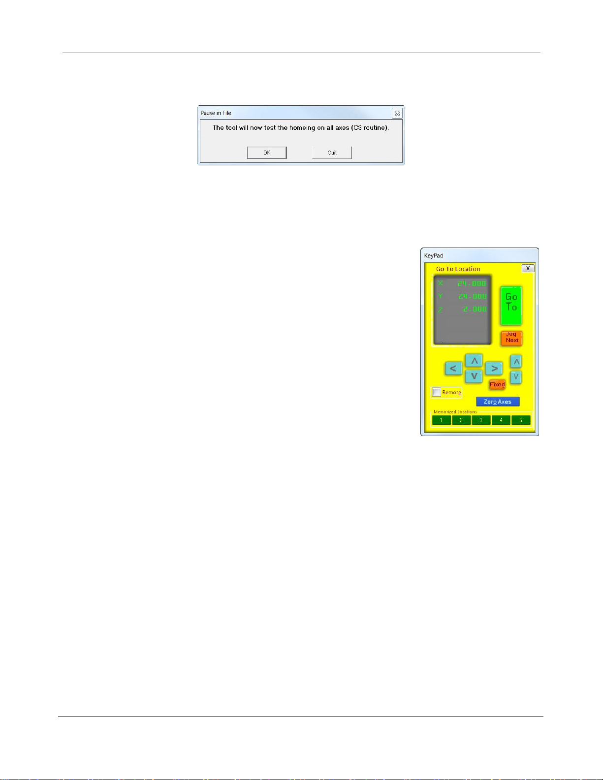
Use the keypad to move to the location where the Z level is located. If zeroing
to a specific fixture, move the tool over it. Close the keypad when the tool is at
the desired position.
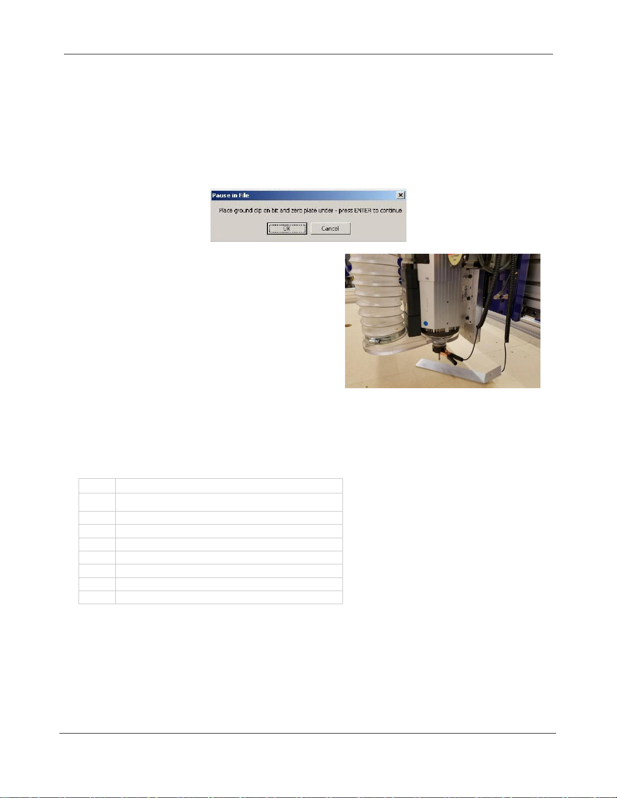
Place the grounding clip on the collet or bit and place the regular Z zero plate below the bit (this routine does
not use the fixed Z zero plate). Click “OK”, and the routine will touch off the zero plate and save the offset
from the fixed Z zero plate. When the plate is removed, the tool will confirm the proximity switch locations
and new Z zero level.
Every time the C3 routine is run the tool will be zeroed at this stored level.
NOTE: Pay attention to where Z zero is set in the CAM file to avoid damaging the table surface or
cutting the wrong depth.
Desktop MAX Automatic Tool Changer (ATC) User Manual SBG00358
© Copyright May, 2022 ShopBot Tools, Inc.
page 19
Zero to Various Z Heights (C2) (Daily Operation)
ATC users will only have to zero one bit to their material or bed height each time the Z zero position is
changed. The remaining bits in the tool rack will also reference the new position.
Once all of the bits have been zeroed to the fixed Z zero plate, any bit can be used to zero to the surface
using the regular Z zero plate.
When the bit is located over the area needed to set as zero,
type “C2” (“Zero Z-Axis w/ Z zero Plate”).
Place the Z zero plate under the bit and place the grounding
clip on it. Click “OK” when both are in place. The Z-axis will
touch off the plate twice, and record this distance for use on
all the tools until this Z offset is reset.
This records a Z offset height within the ShopBot user
variables and applies this to all the other tools in the tool
rack.
Note that the Z offset is reset to the Z home position any time the C3 routine is run. To permanently change
the Z home position, refer to the Get plate offset (CN73) section of this document.
Regularly Used ATC Files
C1
Change tool
C2
Zero Z-axis using Z-zero plate
C3
Home X, Y, and Z-axes using proximity switches
C5
Spindle warmup routine
C6
Turn spindle on
C7
Turn spindle off
C9
Automatic tool change called within a part file
CN72
Zero tools in rack
CN73
Get plate offset (set Z-axis home position)

Desktop MAX Automatic Tool Changer (ATC) User Manual SBG00358
© Copyright May, 2022 ShopBot Tools, Inc.
page 20
Create a Tool Change File
The design software must first have the information to enable the ATC to do a tool change. For the software
to work correctly, the tooling must be designated to specify particular tool holders.
When setting up a tool database inside the design software, create a group named “Tool Changer” or “ATC”.
This will allow separation of tools that are setup specifically for the tool changer.
Within the group, create new tools that will be used with the ATC. The tools created need to have the same
tool number in the characteristics of the tool as the location of that tool holder on the ATC. This tool number
within the design software is what dictates what tool is selected during the tool changing process.
Create a drawing within the design software and toolpath it using the tools under the tool changer group that
you have created. When all toolpaths are created, set the order of the tool paths under the Toolpath List.
Select the save icon (disk) under “Toolpath Operations”. Make sure that the proper post processor is
selected. In VCarve Pro it will read:
ShopBot TC (Inch)(*.sbp) or ShopBot TC (MM)(*.sbp).
In Aspire it will be:
ShopBot(inch)(Toolchange)w/speed(*.sbp) or ShopBot(mm)(Toolchange)w/speed(*.sbp).
NOTE: Pay attention to where Z zero is set in the CAM file to avoid damaging the table surface or
cutting the wrong depth.
Table of contents


