ShopBot PRSalpha User manual
© Copyright 2017 ShopBot Tools, Inc. page 1
ShopBotTools.com888-680-4466 •
Assembly Guide
For PRSalpha and PRSstandard Tools
For all PRS tools shipped after 6/15/2017

Assembly Guide for PRS Alpha and Standard Tools • October 5, 2017
© Copyright 2017 ShopBot Tools, Inc. page 2

Assembly Guide for PRS Alpha and Standard Tools • October 5, 2017
© Copyright 2017 ShopBot Tools, Inc. page 3
Table of Contents
General Safety and Precautions..............................................................................................................7
PRS Quick-Start Process Flow ...............................................................................................................8
Main Parts of PRSalpha ..........................................................................................................................9
Section 1. Setup and Assembly Overview .......................................................................................... 1-1
Electrical Precautions ................................................................................................................. 1-1
Other Electrical Precautions....................................................................................................... 1-1
Safety.......................................................................................................................................... 1-1
Unpacking the Crate................................................................................................................... 1-2
Major Components..................................................................................................................... 1-3
Section 2. Table Assembly .................................................................................................................. 2-1
Introduction ................................................................................................................................ 2-1
Tools Required............................................................................................................................ 2-3
Marking the Rails........................................................................................................................ 2-4
Mount Table Levelers to Legs..................................................................................................... 2-4
Install Table Legs ........................................................................................................................ 2-5
Table Sides for 12” and 24” Z-Axis Congurations.................................................................... 2-6
Stabilize with Lower Table Supports .......................................................................................... 2-7
Connect Side Assemblies .......................................................................................................... 2-7
Install Middle Lower Table Support ............................................................................................ 2-8
Insert T-Nuts in Bottom Slot ....................................................................................................... 2-8
Mount Table Supports and Gussets to Table Legs .................................................................... 2-9
Secure Table Supports and Cross Supports to Table Sides .................................................... 2-10
Install Cross Supports .............................................................................................................. 2-11
Level and Square Table ............................................................................................................ 2-12
Level the Table Sides................................................................................................................ 2-12
Square the Table Sides............................................................................................................. 2-13
Install Rails................................................................................................................................ 2-14
Adjust Front Rail ....................................................................................................................... 2-15
Section 3. Gantry Installation .............................................................................................................. 3-1
Introduction ................................................................................................................................ 3-1
Install Gantry............................................................................................................................... 3-2
Adjust the Rails........................................................................................................................... 3-3
Mount the X-Axis Stop Blocks and Proximity Targets................................................................ 3-3
Section 4. Cable Carrier Installation.................................................................................................... 4-1
Introduction ................................................................................................................................ 4-1
Hardware .................................................................................................................................... 4-2
Prepare the Cable Carrier........................................................................................................... 4-3
Reversing the End Links............................................................................................................. 4-3
X-Axis Cable Carrier ................................................................................................................... 4-4
Install Trough Brackets for ShopBots with 6” Z’s....................................................................... 4-4
Install the X-Axis Trough: 6” Z-Axis............................................................................................ 4-5
Machines with 12” and 24” Z-Axis ............................................................................................. 4-5
Install the Upper X Cable Carrier Bracket .................................................................................. 4-6
Cable Carrier to Upper X Bracket............................................................................................... 4-6

Assembly Guide for PRS Alpha and Standard Tools • October 5, 2017
© Copyright 2017 ShopBot Tools, Inc. page 4
Table of Contents (cont’d)
Cable Carrier to Lower X Bracket............................................................................................... 4-6
Test Cable Carrier Mobility on Both Axes................................................................................... 4-7
X-Axis Cable Carrier Congurations........................................................................................... 4-8
Section 5. Control Box Installation...................................................................................................... 5-1
Introduction ................................................................................................................................ 5-1
Hardware .................................................................................................................................... 5-2
Installation .................................................................................................................................. 5-4
Alternate Mounting for 12” and 24” Z-Axis Models ................................................................... 5-5
Section 6. VFD Installation and Spindle .............................................................................................. 6-1
Introduction ................................................................................................................................ 6-1
VFD Installation........................................................................................................................... 6-1
Hardware .................................................................................................................................... 6-2
Determining the VFD Model ....................................................................................................... 6-2
Voltage Amperage ...................................................................................................................... 6-3
Mounting the 10” VFD ................................................................................................................ 6-3
Mounting the 16” VFD ................................................................................................................ 6-4
Spindle Installation ..................................................................................................................... 6-5
Hardware .................................................................................................................................... 6-5
Lower the Z-Axis Extrusion ........................................................................................................ 6-6
Spindle Mounting Plate .............................................................................................................. 6-6
Attach Spindle ............................................................................................................................ 6-7
Replace Stop Screw................................................................................................................... 6-7
Section 6 Appendix: Table Leg Drawings................................................................................... 6-8
6” Table Leg....................................................................................................................... 6-8
12” Table Leg..................................................................................................................... 6-9
Section 7. Mounting X-Axis Motors .................................................................................................... 7-1
Introduction ................................................................................................................................ 7-1
Hardware .................................................................................................................................... 7-2
Motors ........................................................................................................................................ 7-2
Mount Pinions to Motors ............................................................................................................ 7-2
Identify Motors............................................................................................................................ 7-3
Check Alignment of Pinions with Rack ...................................................................................... 7-3
Adjust Pinions (If Required) ........................................................................................................ 7-3
Mounting Locations.................................................................................................................... 7-4
Position Motors on Tool.............................................................................................................. 7-4
Section 8. Wire and Cable Routing ..................................................................................................... 8-1
Hardware .................................................................................................................................... 8-1
Cable Routing Strategy .............................................................................................................. 8-1
Spindle Power Cable ............................................................................................................ 8-1
Motors and Signal Cables .................................................................................................... 8-1
Spindle Fan Cable Installation.................................................................................................... 8-2
Proximity Switch Installation ...................................................................................................... 8-2
X Proximity Switch...................................................................................................................... 8-2
Route Wiring............................................................................................................................... 8-3
Pneumatic Air Hoses .................................................................................................................. 8-4
Assembly Guide for PRS Alpha and Standard Tools • October 5, 2017
© Copyright 2017 ShopBot Tools, Inc. page 5
General Safety and Precautions
This safety summary contains general safety warnings that should be understood during operation of
this machine. Refer also to General Power Tool Safety Warnings found in User Guide. Failure to ob-
serve these precautions could result in injury.
Learn and understand safe use of the machine. Do not allow untrained individuals
to operate the machine without supervision. Be aware of the location of the Emer-
gency Stop switches at all times.
Eye and ear protection MUST be worn by the machine operator as well as any
bystanders or observers. Flying sawdust, material chips, and other debris can
cause serious eye injury.
Wear closed-toe shoes at all times.
Make sure that your material is properly secured before cutting, and be aware of
any small parts that may come loose after being cut. If a small part catches the
edge of a spinning bit, it can be thrown forcefully in any direction, causing injury
or damage.
Never place your hands on the rails of the ShopBot. Be aware that the machine
may move unexpectedly in any direction, which can cause serious injury if your
hands are in the path of movement.
Never wear gloves while operating the machine. As with any power tool, a glove
can get caught in moving or spinning parts and pull your hand into the machinery.
Never leave a machine running and unattended. Understand that a spinning tool
generates friction and heat, creating a risk of re. This risk is minimized by using
correct chip load, using sharp bits, and by always double-checking your les
before cutting. Be prepared to pause or stop the cut if something seems incorrect
or unsafe.
Keep a working re extinguisher within reach of the machine, for the reasons
listed above.

Assembly Guide for PRS Alpha and Standard Tools • October 5, 2017
© Copyright 2017 ShopBot Tools, Inc. page 6
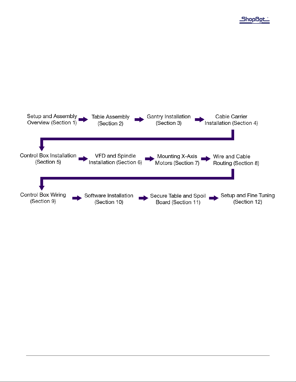
PRS Tool Assembly Process Flow

Assembly Guide for PRS Alpha and Standard Tools • October 5, 2017
© Copyright 2017 ShopBot Tools, Inc. page 7
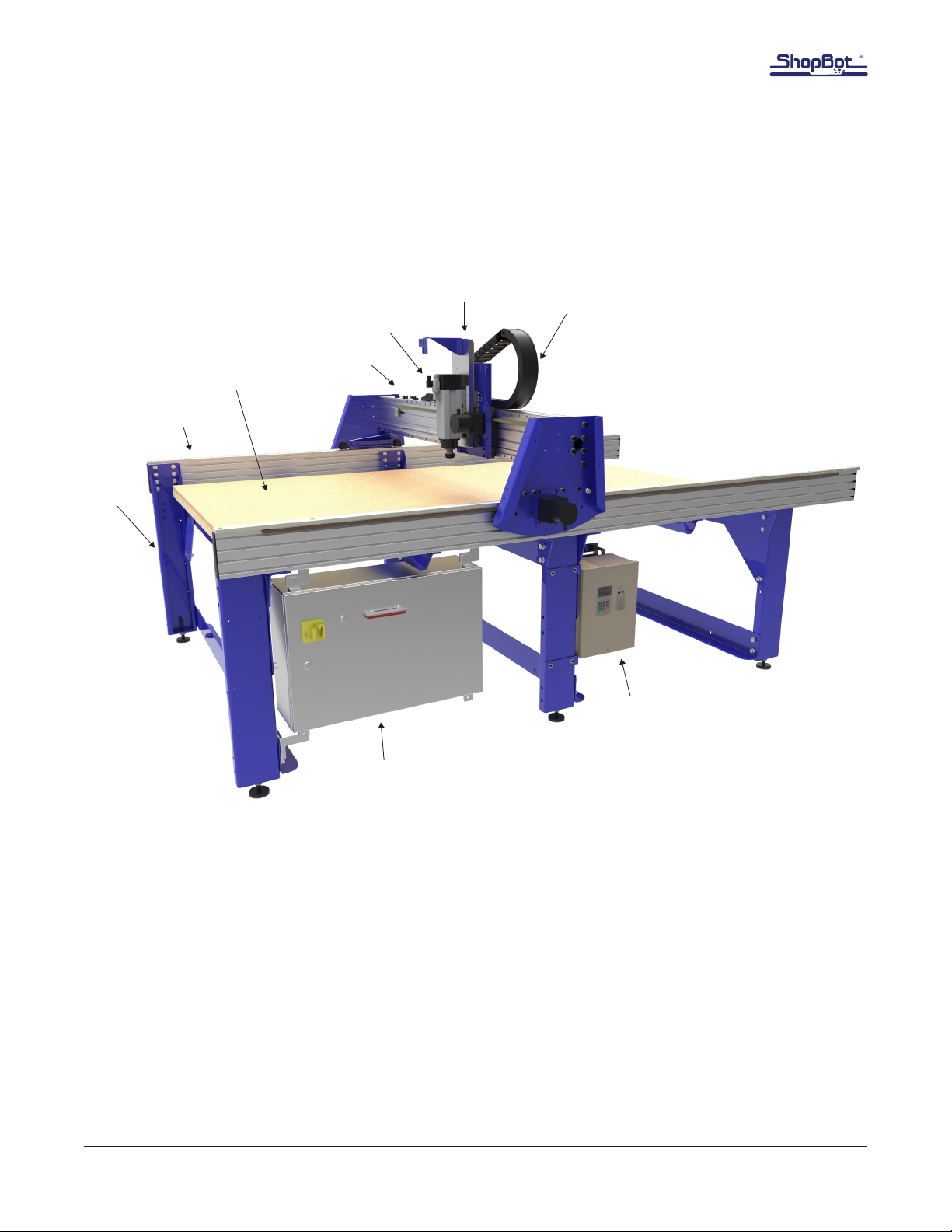
Main Parts of PRSalpha
YZ Car
Spindle
Gantry
Spoil Board
Table Side (Rail)
Control Box
VFD
Frame
E-chain
© Copyright 2017 ShopBot Tools, Inc. page 8
PRS Tool Assembly Process Flow
© Copyright 2017 ShopBot Tools, Inc. page 9
Main Parts of PRSalpha
YZ Car
Spindle
Gantry
Spoil Board
Table Side (Rail)
Control Box
VFD
Frame
E-chain

Section 1: Setup and Assembly Overview • October 5, 2017
© Copyright 2017 ShopBot Tools, Inc. page 1-1
Section 1. Setup and Assembly Overview
Electrical Precautions
A licensed electrician is required to complete the ShopBot setup. Connecting power to the control box
is easiest when the tool is set up and in its nal position. If the tool includes a high frequency spindle
and/or a vacuum blower, these will also need to be connected by an electrician. Wiring diagrams and
specications are located inside the control box door.
Other Electrical precautions:
Motor Connections: DO NOT connect or disconnect motor cables while power is on to the control
box. This can damage or destroy the motors or drivers.
Induced Currents: AVOID moving axes by hand when the control box is powered off. If it is unavoid-
able, do so very slowly. Spinning the motors can generate an electric charge and damage drivers or
other electronic components.
Static Discharge: Follow all wiring and grounding instructions - electronic circuits are very sensitive
to static and power surges. Avoid vacuuming around the machine before it is properly grounded, as
vacuums can generate a large amount of static electricity that can damage the control box.
Safety
WARNING: RISK OF ELECTRIC SHOCK
The control box must be connected to electrical service by a licensed electrician,
who has experience with industrial equipment. Personal injury or damage to the
machine may occur if an unlicensed individual performs this job.
Use caution when lifting boxes and assem-
bled components out of the crate. Having an
assistant will make things much easier – partic-
ularly when unpacking the crate and lifting the
gantry onto the table rails. Do not attempt to lift
the gantry without assistance.

Section 1: Setup and Assembly Overview • October 5, 2017
© Copyright 2017 ShopBot Tools, Inc. page 1-2
Unpacking the Crate
ShopBot components arrive in two packages: a large wooden crate, and a long box. Contact the ship-
ping company if either piece is missing, or if they do not arrive together.
The components are packaged to avoid shifting during shipping. Use a large screwdriver to pry off the
clips on top on the crate, and a Phillips head screwdriver to uncrate the components. It will require two
people to lift out some of the heavier pieces.
Read through the assembly directions, and sort the components by their function to help organize the
assembly process. Sort hardware by size to reduce the amount of time searching for the correct bolts,
nuts and washers for a given stage of the assembly.
Many components of the machine come pre-assembled to reduce the number of assembly steps. In
many places, bolts or hardware may be loosely t in place to show their intended location. Remove
this hardware prior to tting the applicable component into place.

Section 1: Setup and Assembly Overview • October 5, 2017
© Copyright 2017 ShopBot Tools, Inc. page 1-3
Major Components:
The base of the machine is referred to as the table
frame.
The two long aluminum extrusions on each side
are called table sides. Atop the sides are the rails,
which create the path of travel for the X-axis.
The table sides and rails are included in the long
cardboard package secured to the top of the crate.
The assembly that rides along the table sides is
called the gantry.
The gantry consists of an extruded aluminum
beam, which has been tted with linear bearings
and gear rack. This forms the path of travel for the
Y-axis.
The blue plates on either side of the gantry are
referred to as end plates.
The YZ car moves across the gantry, and controls
the height of the cutter head (either a router or
high-speed spindle, depending on the tool).
Section 1: Setup and Assembly Overview • October 5, 2017
© Copyright 2017 ShopBot Tools, Inc. page 1-4
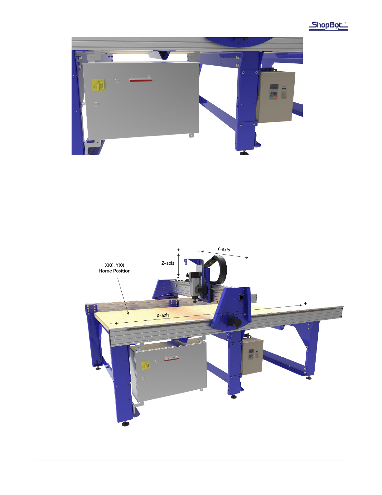
The control box is the “brain” of the machine and contains a control board, motor drivers, and other
electronic components that allow the tool to move with precision, accuracy, and power. It connects to
the PC through a single USB cable.
The variable frequency device (VFD) is used on machines that contain a spindle only (not a router).
It controls speed and power for the spindle. The control box provides the VFD with on/off signals, but
speed is controlled through an RPM controller unit, which connects to the PC through a separate USB
cable.
In most cases, the X-, Y-, and Z-axes will be referred to in respect to the machine. The XY Home
Position is also indicated here.

Section 2: Table Assembly • October 5, 2017
© Copyright 2017 ShopBot Tools, Inc. page 2-1
Section 2. Table Assembly
Introduction
The ShopBot table provides a rm foundation for all other components. This section contains
instructions to assemble, square, and level the table for correct and optimal performance.
The diagrams in this manual depict a 96” x 48” table, the most common ShopBot table size. The table
layout may look a little different (fewer or more legs, tool changer bar, etc.) depending on the size and
shape of your tool (as well as any accessories included), but the same basic steps will be followed.
The table drawings provided at the end of this guide will detail specic measurements for other
congurations.
Note: It is critical to follow the table drawing carefully to ensure correct assembly of the table and
accessories.
The table leveling and squaring steps should be completed with the table in its nal location. Moving
the table after these steps may alter the level and square.
Note: This section shows a conventional table with a 6” Z-axis. Tables congured for 12” and 24” axes
have extra table side extrusions and table legs with added mounting holes.

Section 2: Table Assembly • October 5, 2017
© Copyright 2017 ShopBot Tools, Inc. page 2-2
Hardware
Part Name Quantity ShopBot P/N Notes
Rail 2 001872
Table side 2 000925
Upper table support 4 000915 Different for other lengths
Lower table support 3 000921 Different for other lengths
Table cross support 48E 2 000926 Different for other lengths
Table leg 6 000919 Different for other lengths
Table gusset 6 000770 Different for other lengths
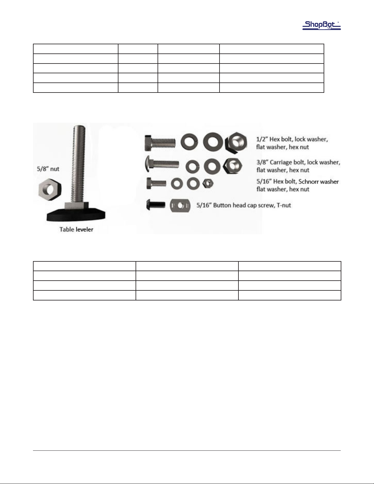
Except for the table levelers, all of this hardware is included in the small box marked “table
hardware”:
Part Name Quantity ShopBot P/N Notes
1/2-13x1-1/2 Hex Bolt Varies 001956 Used for components to leg
1/2" Lock Washer Varies 000588 Used for components to leg
1/2" Flat Washer Varies 000029 Used for components to leg
1/2-13 Hex Nut Varies 000440 Used for components to leg
5/16-18” x 3/4” Hex Bolt Varies 000529 Used for cross supports, leg
5/16” Schnorr Washer Varies 004487 Used for leg
5/16” Flat Washer Varies 000848 Cross supports, leg
5/16-18 T-Nut Varies 002498 Legs, cross supports, rails
5/16-18x3/4 Button Head
Cap Screw Varies 002033 Used for rails
5/8-11 Hex Nut Varies 000160 1 per table leg
5/8-Table Leveler w/Nut Varies 002926/000862 1 per table leg
Section 2: Table Assembly • October 5, 2017
© Copyright 2017 ShopBot Tools, Inc. page 2-3
Part Name Quantity ShopBot P/N Notes
3/8-16x1 1/2 Carriage bolt Varies 000953 Used to secure base board
3/8” Lock washer Varies 000092 Used to secure base board
3/8” Flat washer Varies 000444 Used to secure base board
3/8-16 Hex nut Varies 000452 Used to secure base board
* Specic quantities can be found on the packing list enclosed with the hardware.
Tools Required
Marker (or other writing tool) Tape Measure Wrench or Socket, 5/16”
Mechanical Square Rubber Mallet Wrench or Socket, 3/8”
Safety Straps (Optional) Wrench or Socket, 5/8” Wrench, 1”
String/Twine (at least 30ft) Wrench or Socket, 1/2” Wrench, Allen, 5/16”
Marking the Table Sides
Remove table sides from packaging and lay them on the oor side-by-side. Locate where the Home
Position (X = 0) will be.
Note for International Customers: The location of the table legs and cross supports along the X-rails
can be adjusted slightly to reect metric units.
Section 2: Table Assembly • October 5, 2017
© Copyright 2017 ShopBot Tools, Inc. page 2-4
Locate your machine’s corresponding table drawing at the back of this assembly manual. Starting
from the Home Position, use a tape measure and permanent marker to indicate on the inside of the
rails where each table leg and cross support
will attach.
If you haven’t already, it is helpful to then
move the rails into the general space that
the nished tool will occupy.
Note: This image indicates the rail marking
locations for a 96” tool. The positions will
differ for other table congurations.
Orient table sides into approximate location
that the tool will occupy.
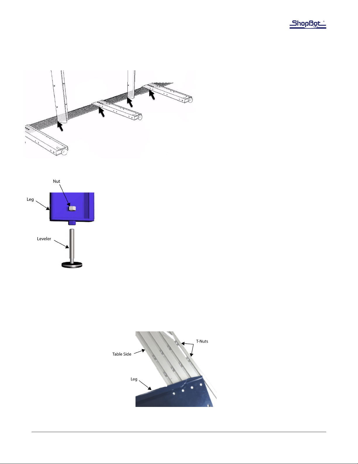
Mount Table Levelers to Legs
Remove table legs from packaging. Screw leveler approximately half way into
the bottom of each table leg. Thread a 5/8” hex nut onto the leg leveler. Keep
nut loose until table is leveled.
Thread the middle leg levelers all the way up to ensure that the feet do not
interfere during the leveling procedure.
Note: During assembly, some holes may require tapping to remove excess
powdercoating.
Install Table Legs
Insert eight T-nuts per table leg into the T-slots in the pattern shown, with the rough side down. Note
the line marked earlier for alignment. Ensure to insert the T-nuts for the middle table legs in the T-slots
prior to assembling the end table legs.

Section 2: Table Assembly • October 5, 2017
© Copyright 2017 ShopBot Tools, Inc. page 2-5
With the T-nuts in place, position the table legs
to line up with them. Support the table legs so
they stay level during installation.
Secure the legs to T-nuts in rail with 5/16” hex bolts,
Schnorr washers, and at washers.
Note: Schnorr washers are concave washers. Install them
with curve cradling the bolt head. Note that they can make
threading the bolts into the T-nuts difcult. If necessary, use
a zip tie or other shim behind the T-nut to force it closer to
the surface of the slot so it is easier to catch the threads
with the bolt assembly.
Hold a framing square against the leg and the table side
while bolts are tightened to ensure leg is installed at a 90o
angle. Hand-tighten the top and bottom bolts when the
leg is square. Do not tighten other bolts at this time.
Repeat this process until all remaining legs are installed.
Section 2: Table Assembly • October 5, 2017
© Copyright 2017 ShopBot Tools, Inc. page 2-6
Table Sides for 12” and 24” Z-Axis Configurations
Tables congured for 12” and 24” Z-axes have
extra table sides and legs with added mounting
holes.
Assembly of these table congurations is identical
with what’s shown, with the exception of these
unique parts and extra mounting hardware.
Table supports and gussets will go under the table
side, and the rails will mount to the top of the
table sides.
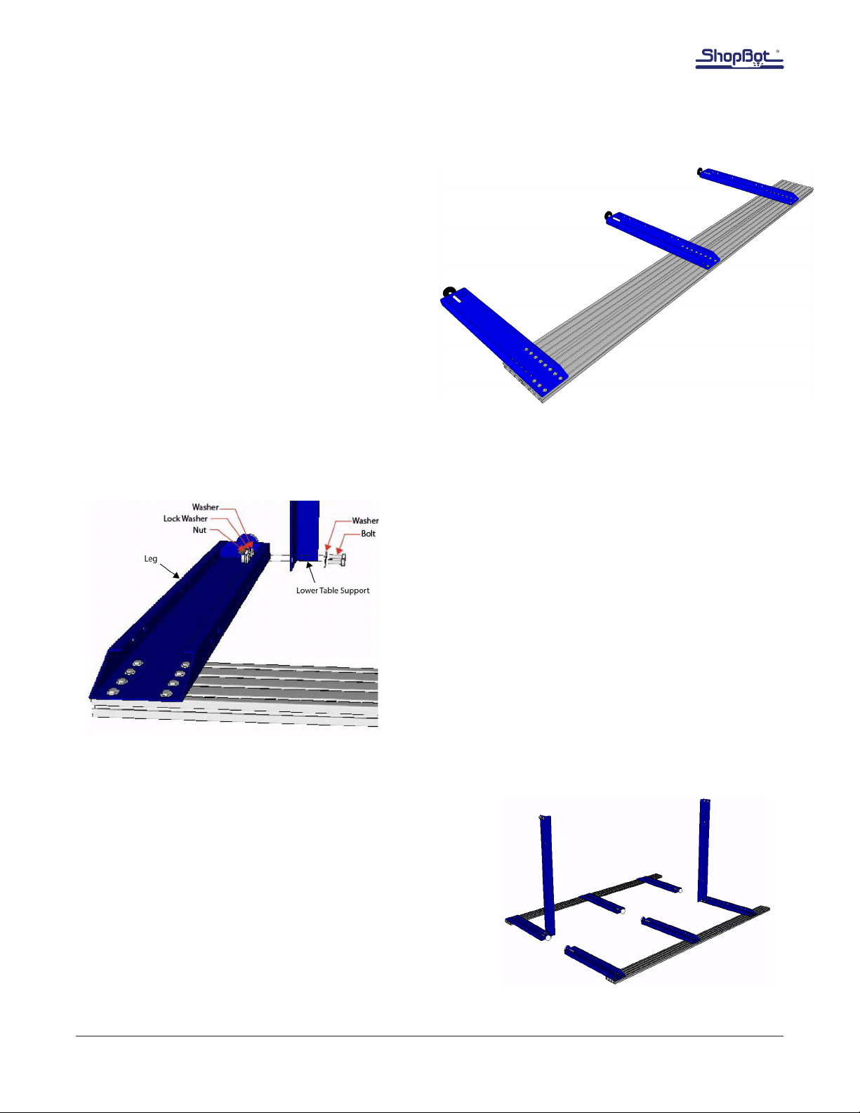
Stabilize with Lower Table Supports
Install lower table support to the rst exterior table leg
with the L shape facing the interior of the machine with
1/2” bolt and at washer on one side, and at washer,
lock washer, and nut on the back side. Tighten the bolts
only until they are snug; do not tighten them completely
at this time.
Repeat the step on the opposite exterior table leg, on the
other table side. These lower table supports will act as
“kickstands” to hold the table sides up for assembly.
Raise each table side. If performing the assembly alone, use
safety straps to secure the sides in place to prevent injury or
damage to the frame.
Note: If a leveler foot pops off while lifting the sides in place,
simply place the foot under the ball of the hardware and
press down on the table side to reseat it.

Section 2: Table Assembly • October 5, 2017
© Copyright 2017 ShopBot Tools, Inc. page 2-7
Connect Side Assemblies
Attach lower table supports to
opposite table sides.
If working alone, keep safety strap
attached until the frame is self-
supporting to prevent injury or damage
to tool.
Note: Do not install upper bolt on
lower front right side - this is where the
control box will attach.
Square table sides with the lower
supports and snug the bolts enough to
preload the lock washers.
Install Middle Lower Table Support
Install the middle lower table support. The horizontal ange
should point to the front/ush end of the side rails.
Secure middle lower table support to middle set of legs
with the same order of 1/2” hex bolt and at washer on
one side, and at washer/lock washer/hex nut on the
back side. Snug the bolts enough to preload the lock
washers.
If the middle table levelers are touching the oor, raise
them until they no longer make contact.
Other manuals for PRSalpha
3
This manual suits for next models
1
Table of contents
Other ShopBot Tools manuals


