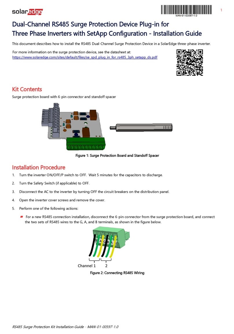
Shopify EVP-3PH User manual

FEATURES
TECHNICAL DATA
SAFETY PRECAUTIONS
1. The device must be installed by a qualified person,
2. Disconnect all power before working on the device. Don’t touch any terminal
when the power is ON.
3. Verify correct terminal connection when wiring.
4. Don’t dismantle or repair the device whether it operates normally, otherwise
no responsibility is assumed by producer and seller.
5. Never use the device at the site which can be invaded by corrode gas, strong
sunshine light and rain.
6. Clean the device with a dry cloth.
7. Fail to follow these instructions will result in serious injury or death.
3 PHASE VOLTAGE AND CURRENT PROTECTOR
EVP-3PH
Please read complete instructions prior to installation and operation of
the device.
Microcontroller based
Digit display for operating voltage and current value
Protect electrical device against over/under voltage, overcurrent,
three phase asymmetry and incorrect phase sequence.
Voltage measurement accuracy =1%
Parameters setting by keys
LEDs indication for over/under voltage and over current faults
5 Module, DIN Rail mounting
≤50% at 40°C(without condensation)
-1-
Iset<Ir<80A:Ta; Ir=80A: ≤0.1s
Overcurrent setting range 5A~63A
Phase sequence setting
Asymmetry setting range
Hysteresis
Auto reset setting
Asymmetry trip delay
Ts:5s~600s
Ta:5s~600s
OFF-1~20
ON-OFF
ON/OFF
20V~99V-OFF
0.1s; ≤350V:0.02s
≤120V:0.5s ,<120V:0.1s
10s
450V
Protection degree IP20
Pollution degree 3
Electrical life
Altitude
Operating temperature
Storage temperature
Mechanical life
10 5
106
≤2000m
-5°C~40°C
-25°C~55°C
Voltage measurement accuracy ≤1%(over the whole range)
Rated insulation voltage
Humidity
Output contact 1NO
Operation voltage range
AC 50V~400V
Rated frequency
50/60Hz
220~300V
AC 220V
Overvoltage(U>) setting range
Undervoltage(U<) setting range
Rated supply voltage
120~210V
Undervoltage(U<) trip delay
Reset/start delay
Overvoltage(U>) trip delay
Overcurrent(I>) trip delay
* Operating current value
Overcurrent faults trip delay range
Continuous overcurrent times setting
Overvoltage and asymmetry: 5V
Undervoltage:3V
ON-OFF
Phase sequence protection
ON-OFF ON
220V~300V
120V~210V
5s~600s
5A~63A
20V~99V-OFF
OFF-1~20
5s~600s
1V
1V
1s
1A
1V
1
1s
250V
170V
5s
63A
50V
3
OFF
15s
Asymmetry trip value
Continuous overcurrent faults times
Auto reset setting
Overcurrent trip delay
Setting range
Step Factory setting
Overvoltage trip value
Reset/start delay
Undervoltage trip value
Technical parameter
Overcurrent trip value
FRONT-FACE PANEL
Digit+/Inquiry of
last fault
Display
Menu selection
Manual ON/OFF
Digit-
Reset/
AAA
VVV
L1 L2 L3
MM
Switch on/off manually
Press the key for
more than 0.5s
>0.5s
>0.5s
L3
L1 L2
-
:Synchronous mode; :Asynchronous mode
Operation mode
Output indicator
Inquiry of faults
Display the last fault value and flash.
Exit from display after 3s.

Main menu setting
V
V
V
V
V
V
V
V
V
V
A
A
A
A
A
A
A
A
A
A
M
M
M
M
M
M
M
M
>2s
L3 main display
End setting, press OK to exit from
settings
V
A
In=63A
L3
Only L3 display when setting. L1 and L2 don’t display.
M
M
Overvoltage trip value setting V
Change the setting value by pressing
keys.
Undervoltage trip value setting V
Change the setting value by pressing
keys.
Reset/start delay setting S
Change the setting value by pressing
keys.
Overcurrent value setting A
Change the setting value by pressing
keys.
Overcurrent faults trip delay setting S
Change the setting value by pressing
keys.
Asymmetry ratio setting V
Change the setting value by pressing
keys.
Continuous overcurrent faults times
setting
Change the setting value by pressing
keys. OFF: turn off the function.
Phase sequence setting
Change the setting states by pressing
keys.
OFF: turn off the function;
ON: turn on the function;
Auto reset setting
Change the setting states by pressing
keys.
OFF: turn off the function;
ON: turn on the function;
Long press can increase or decrease repidly.
The relay will automatically exit from the menu and not save the
modified value if not pressing the keys for continuous 60s during
setting.
-2-
V
A
Operation mode setting
M
Change the setting states by pressing
keys.
:Synchronous mode;
:Asynchronous mode
:Synchronous mode; In this mode the
device works as a three phase voltage
protector with N,L1,L2,L3 as single
circuit
:Asynchronous mode : In this mode the
device works as three Individual single
phase protectors which can be
connected to three separate circuits.
Also the device can identify & stop/trip/
reset each of the three circuits
independently
i.e "N - L1" & "N - L2" & "N - L3"
( Modes explained in the bottom tab )

Voltage operating values display on upper L1-L2-L3 and
synchronous over voltage faults code display on the lower
L1-L2- L3
U> faults display(synchronous)
VVV
AAA
Voltage operating values display on upper L1-L2-L3 and
asynchronous over voltage faults code display on the lower
L1-L2- L3
U> faults display(asynchronous)
VVV
AAA
U< faults display(synchronous)
VVV
AAA
U< faults display(asynchronous)
VVV
AAA
A
Reset/start delay display(synchronous)
VVV
AAA
Reset/start delay display(asynchronous)
VVV
AAA
I> faults display(synchronous)
VVV
AAA
I> faults display(asynchronous)
VVV
AA
Display of phase sequence fault
VVV
AAA
Voltage operating values display on upper L1-L2-L3 and
asymmetry fault code display on lower L2 during the counting of
start delay; After the delay is over, the output relay closes.
Display of (only synchronous)asymmetry fault
VVV
AAA
Display of (synchronous)continuous I> faults
VVV
AAA
Display of (asynchronous)continuous I> faults
Display for continuous overcurrent faults after reset/start delay is over.
overcurrent faults times is more than preset times.
VVV
A AA
Voltage operating values display on upper L1-L2-L3 and delay
time flashes on the lower L3 during the counting of start delay; After
the delay is over, the output relay closes.
Voltage operating values display on upper L1-L2-L3 and delay
time flashes on the lower L1-L2- L3 during the counting of start
delay; After the delay is over, the output relay closes.
Voltage operating values display on upper L1-L2-L3 and
synchronous under voltage faults code display on the lower
L1-L2- L3
Voltage operating values display on upper L1-L2-L3 and
asynchronous under voltage faults code display on the lower
L1-L2- L3
Voltage operating values display on upper L1-L2-L3 and
synchronous over current faults code display on the lower
L1-L2- L3
Voltage operating values display on upper L1-L2-L3 and
asynchronous over current faults code display on the lower
L1-L2- L3
Display for continuous overcurrent faults after reset/start delay is over.
overcurrent faults times is more than preset times.
Start the relay after reset manually.
Disconnect the overload device
Start the relay after reset manually.
Disconnect the overload device
Display L1-L3-L2 when phase failure fault occurs. User can
change the position of L2 and L3 after disconnected supply.
-3-

Manual reset
Auto reset function is off.
U
0.1s
Ton Ton Ton
0.5s
Iset
Imax
Ir
Ta
Ton Ton 0.1s Ton
Asy
5V
0%
10s
<10s
The device will begin counting of reset/start delay after reset for
faults.
OPERATING INSTRUCTIONS
O-OFF O-OF F O-OF FO-OFF
L1 L2 L3N
N L1 L2 L3
IN
N L1 L2 L3
123 4
567 8
N L1 L2 L3
N L1 L2 L3
A A A
V V V
L1 L2 L3
MM
SYMBOL
WIRING DIAGRAM
Rated operating current of circuit breaker is 75% maximum current of the relay
Ie=0.75x Imax
LOAD
LOAD
LOAD
Overvoltage and undervoltage
Hys(U> -5V)
Hys(U< +3V)
U< threshold
U> threshold
Overcurrent
Asymmetry
Ts: Reset/start delay
Ta: Overcurrent faults trip delay
FUNCTION DIAGRAMS
If a voltage fault was detected when the reset/start delay of relay is
counting, the output relay opens and faults indication LED lights up.
Voltage faults: if input voltage was detected to have returned to Hys
after tripped for voltage faults, the relay will reset automatically and
begin the counting of reset/start delay.
Current faults: After the relay tripped for current faults, it will reset
automatically begin the counting of reset/start delay.
The operating voltage and current values will be displayed on screen
when the relay is operating normally. If a voltage or current fault was
detected, the output relay opens and faults code display.
L3
L1 L2
-4-
DIMENSIONS
90
45
N L1 L2
IN
N L1 L2
123
567
89.5
L3
L3
4
8
65.5
>0.5s
A A
Popular Surge Protector manuals by other brands
Patton electronics
Patton electronics 574 user manual
Stratitec
Stratitec MultiStage S3002 Instructions for use
M-system
M-system 6SN instruction manual

Cable Innovations
Cable Innovations DLPS-15D Installation and Information Sheet

ABB
ABB OVRHTE product manual

Cooper Bussmann
Cooper Bussmann BRICK 6125TD Specification sheet
Hubbell
Hubbell GAI-TRONICS 12576-120 quick start guide
Micro Innovations
Micro Innovations SP01F quick start guide
Digitus
Digitus DN-95424 Quick installation guide
NXP Semiconductors
NXP Semiconductors BZA800AL Series datasheet
Eaton
Eaton Memshield 4 Installation instruction
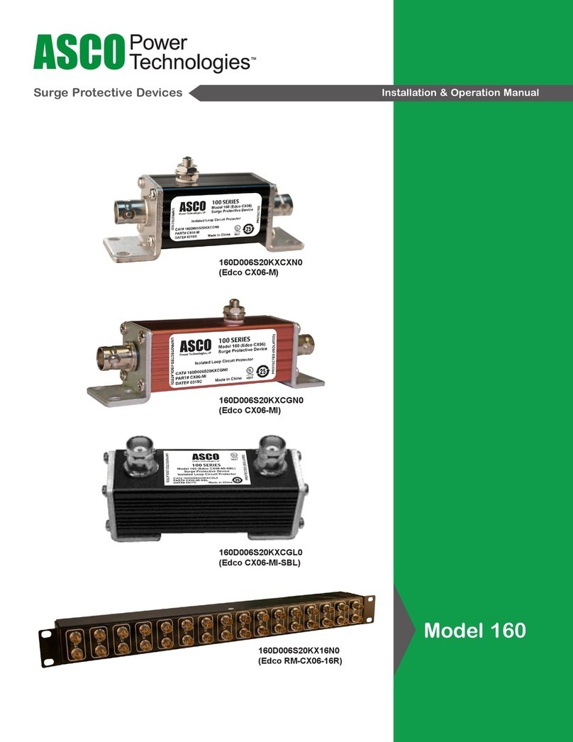
Asco
Asco 160 Installation & operation manual
