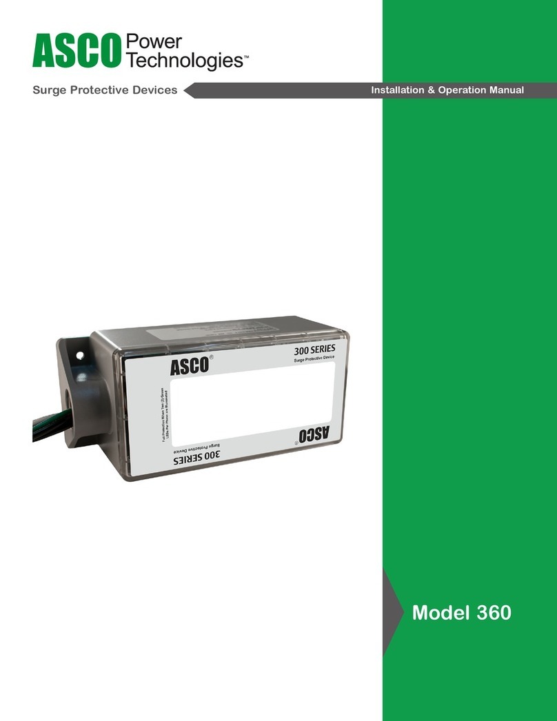
Asco 160 User manual

Surge Protective Devices Installation & Operation Manual
Model 160
160D006S20KXCXN0
(Edco CX06-M)
160D006S20KXCGN0
(Edco CX06-MI)
160D006S20KXCGL0
(Edco CX06-MI-SBL)
160D006S20KX16N0
(Edco RM-CX06-16R)

© 2020 ASCO Power Technologies. All Rights Reserved
2
IO-75025
01/2020
For access to self-service tools and chat support visit se.com/us/en/work/support or call 1-888-778-2733 for technical assistance
ASCO Model 160 (EDCO CX and RM-CX Series)
Surge Protectective Device (SPD)
Safety Information
Important Information
Read these instructions carefully and look at the equipment to become
familiar with the device before trying to install, operate, service or maintain it.
The following special messages may appear throughout thisbulletin or on the
equipment to warn of potential hazards or to call attention to information that
clarifies or simplifies a procedure.
The addition of either symbol to a “Danger”or “Warning” safety label
indicates that an electrical hazard exists which will result inpersonal
injury if the instructions are not followed.
This is the safety alert symbol. It is used to alert you to potential
personal injury hazards. Obey all safety messagesthat follow this
symbol to avoid possible injury or death.
DANGER
DANGER indicates a hazardous situation which, if not avoided,
will result in death or serious injury.
WARNING
WARNING indicates a hazardous situation which, if not avoided,
could result in death or serious injury.
CAUTION
CAUTION indicates a hazardous situation which, if not avoided,
could result in minor or moderateinjury.
NOTICE
NOTICE is used to address practices not related to physical injury. The safety
alert symbol shall not be used with this signal word.
Please Note
Electrical equipment should be installed, operated, serviced, and maintained only
by qualified personnel. No responsibility is assumed by ASCO Power Technologies
for any consequences arising out of the use of this material.
A qualified person is one who has skills and knowledge related to the
construction, installation, and operation of electrical equipment andhas received
safety training to recognize and avoid the hazards involved.

© 2020 ASCO Power Technologies. All Rights Reserved 3
IO-75025
01/2020
For access to self-service tools and chat support visit se.com/us/en/work/support or call 1-888-778-2733 for technical assistance
ASCO Model 160 (EDCO CX and RM-CX Series)
Surge Protectective Device (SPD)
Introduction The ASCO Model 160 Surge Protective Devices (SPDs) implement three-
stage hybrid technology. The SPDs address over-voltage transients with a
primary Gas Discharge Tube (GDT) and secondary Silicon Avalanche Diode
(SAD) components. Overcurrent protection is mitigated with solid-state
resettable fuses — PTCs.
The Model 160 SPDs are designed in accordance with NFPA 780
requirements, with up to 20 kA of surge current capability. The Model 160
with Gas 14th character has an isolated ground option and is recommended
for use at the camera-end.
HAZARD OF ELECTRIC SHOCK, EXPLOSION, OR ARC FLASH
• Apply appropriate personal protective equipment (PPE) and follow safe
electrical work practices. See NFPA 70E, NOM-029-STPS or CSA Z462.
• This equipment must only be installed and serviced by qualied electri-
cal personnel.
• Turn o all power supplying this equipment before working on or inside
equipment.
• Always use a properly rated voltage sensing device to conrm power is o.
• Replace all devices, doors and covers before turning on power to this
equipment.
• This equipment must be eectively grounded per all applicable codes.
Use an equipment-grounding conductor to connect this equipment to the
power system ground.
• Conrm that the Surge Protective Device voltage rating on the module
or nameplate label is not less than the operating voltage.
• This equipment must be installed inside an enclosure and located so,
as to prevent accidental contact with terminals during maintenance or
servicing.
• Do not place this product in service on any signal line capable of
supplying more than 150 mA continuously.
Failure to follow these instructions will result in death or serious injury.
WARNING: This product can expose you to chemicals including
DINP, which is known to the State of California to cause cancer, and
DIDP which is known to the State of California to cause birth defects
or other reproductive harm. For more information go to: www.
P65Warnings.ca.gov.
NOTICE
LOSS OF SURGE SUPPRESSION
• Make certain that Surge Protective Device is disconnected from the
circuit it is protecting before conducting high potential insulation testing.
Failure to follow these instructions can result in equipment damage.
DANGER

© 2020 ASCO Power Technologies. All Rights Reserved
4
IO-75025
01/2020
For access to self-service tools and chat support visit se.com/us/en/work/support or call 1-888-778-2733 for technical assistance
Installation • Turn o all power supplying this equipment before working on or inside
equipment.
For 160D006S20KXCXN0 Head-End Equipment:
1. Connect the 160D006S20KXCXN0 in line with the coaxial cable.
Connect the side labeled “EQUIP” to the adjacent head-end equipment.
2. Connect incoming coaxial cable to the side of the 160D006S20KXCXN0
labeled “CABLE”.
3. Connect a ground wire (10-12 AWG) between the 160D006S20KXCXN0
ground terminal and the AC power ground of head-end equipment.
Keep this wire as short and straight as possible.
For 160D006S20KXCGN0 and 160D006S20KXCGL0 Camera-End
Protection (with Isolated Ground):
1. Connect the 160D006S20KXCGN0 or 160D006S20KXCGL0 in line with
the coaxial cable. Connect the side labeled “EQUIP” to the adjacent
camera.
2. Connect incoming coaxial cable to the side of the ASCO
160D006S20KXCGN0 or 160D006S20KXCGL0 labeled “CABLE”.
3. Connect a ground wire (10-12 AWG) between the ASCO
160D006S20KXCGN0 or 160D006S20KXCGL0 ground terminal and
either the AC power ground or equipment building ground at the camera
location. Keep this wire as short and straight as possible.
For 160D006S20KX16N0 Rack Mount Unit:
1. The ASCO Model 160 is designed to be installed in a standard 19”
equipment rack and take up 1 unit (1U) of space. Secure unit to rack
using the four slots and four screws (not provided).
2. Connect ground wire #12-6 AWG using a #10 ring terminal from the
ground stud on backside of unit to an approved building ground. Wire
must be short and as straight as possible.
3. Connect incoming wire from video equipment to a BNC connector on
marked “IN” on front of the Model 160.
4. Complete the circuit by connecting from the corresponding BNC
connector marked “OUT” to the video camera.
• Replace the barrier, cover/door and/or trim to the equipment.
• Equipment may be re-energized after all the above steps are complete.
HAZARD OF ELECTRIC SHOCK, EXPLOSION, OR ARC FLASH
• These protectors are intended for indoor use on communication loop
circuits which have been isolated from the Public Switch Telephone
Network.
• Do not expose the communication loop to contact with the electric light
or power conductors.
• Install the protectors as per the applicable requirements of the National
Electric Code, ANSI/NFPA 70.
Failure to follow these instructions will result in death or serious
injury.
ASCO Model 160 (EDCO CX and RM-CX Series)
Surge Protectective Device (SPD)
DANGER
© 2020 ASCO Power Technologies. All Rights Reserved 5
IO-75025
01/2020
For access to self-service tools and chat support visit se.com/us/en/work/support or call 1-888-778-2733 for technical assistance
Figure 1: Connection Diagram
ASCO Model 160 (EDCO CX and RM-CX Series)
Surge Protectective Device (SPD)
Head-End
Equipment
Camera-End
Equipment
To AC Power Ground
(Keep ground wire
as short as possible)
(Keep ground wire
as short as possible)
To AC Power Ground
or Building Ground
Model
160D006S20KXCGN0
Model
160D006S20KXCXN0 or
160D006520KX16NO
(16 Channel Rackmount)

© 2020 ASCO Power Technologies. All Rights Reserved
6
IO-75025
01/2020
For access to self-service tools and chat support visit se.com/us/en/work/support or call 1-888-778-2733 for technical assistance
General Technical
Specication
ASCO Model 160 (EDCO CX and RM-CX Series)
Surge Protectective Device (SPD)
Operating Voltage 5 VDC
Clamping Voltage 6 VDC
Operating Current 0.15 A
Peak Surge Current 20 kA (8 x 20 µs)
Frequency Range 0 to 20 MHz
Insertion Loss < 0.1 dB at 20 MHz
Response Time < 0.5 ns
SPD Technology GDT, SAD, w/ Series PTC
Connection Type BNC, 50/75 Ohm
Operating Temperature -40°C to +85°C
Dimensions (in / mm) 160D006S20KXCXN0 = 1.5 x 1.0 x 3.25 in.
[38.1 x 25.4 x 82.55 mm]
160D006S20KXCGN0 = 1.5 x 1.0 x 4.0 in.
[38.1 x 25.4 x 101.6 mm]
160D006S20KXCGL0 = 1.7 x 1.4 x 2.8 in.
[43.18 x 35.56 x 71.12 mm]
160D006S20KX16N0 = 1.75 x 19.0 x 2.0 in. (1U)
[44.45 x 482.6 x 50.8 mm]
Weight (lb / kg) 160D006S20KXCXN0 = 0.14 lbs [0.07 kg]
160D006S20KXCGN0 = 0.19 lbs [0.09 kg]
160D006S20KXCGL0 = 0.19 lbs [0.09 kg]
160D006S20KX16N0 = 3.2 lbs [1.45 kg]
Certications UL 497B
Limited warranty 5 Years

© 2020 ASCO Power Technologies. All Rights Reserved 7
IO-75025
01/2020
For access to self-service tools and chat support visit se.com/us/en/work/support or call 1-888-778-2733 for technical assistance
Model Cross Reference MODEL
Former Model Name APPLICATION
160D006S20KXCXN0
Edco CX06-M Head-End
160D006S20KXCGN0 (w/ Isolated Ground)
Edco CX06-MI Camera-End
160D006S20KXCGL0 (w/ Isolated Ground)
Edco CX06-MI-SBL Camera-End
160D006S20KX16N0
Edco RM-CX06-16R
16 Channel Coax,
Head End
ACCESSORY
PCDIN
11604KIT-CX
DIN Mounting Kit for
160D006S20KXCXN0
160D006S20KXCGL0
160D006S20KXC6N0
ASCO Model 160 (EDCO CX and RM-CX Series)
Surge Protectective Device (SPD)

IO-75025 Rev- 01-20
14550 58th Street North
Clearwater, Florida 33760
se.com/us/en/work/support
1-888-778-2733
While every precaution has been taken to ensure accuracy and
completeness in this literature, Schneider Electric assumes no
responsibility, and disclaims all liability for damages resulting from
use of this information or for any errors or omissions.
This manual suits for next models
4
Table of contents
Other Asco Surge Protector manuals