Shopsmith MARK V 505 User manual
MARK V MODEL 505/510
ROUTER TABLE
522155
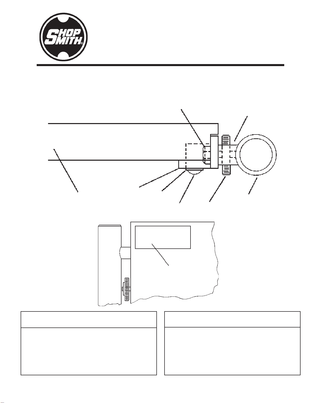
EXPLODED VIEW
Ref. Part Item
No. No. Description Qty.
PARTS LIST
— 522155 Router Table Package
—522150 . Table Assembly (Inc. 1-9) ................ 1
1522180 . . Router Table With Label (Inc. 2) ... 1
2522014 . . . Warning Label .......................... 1
3514667 . . Table Tube ................................. 2
4514440 . . Jackscrew.................................. 4
5522136 . . Table Spacer ............................. 6
6515294 . . Keps Nut ................................... 6
7522134 . . Bracket ...................................... 2
8120380 . . Split Lock Washer ..................... 6
9521692 . . Button Head Screw ................... 6
10 521991 . Router Plate & Hardware (Not Shown) 1
Ref. Part Item
No. No. Description Qty.
2
1
7
8
94
3
6
5

MARK V MODEL 505/510 ROUTER TABLE 522155
Page 2
INTRODUCTION
The Router Table can be used with the
Shopsmith MARK V Model 505 & 510.
This instruction manual covers safety, assem-
bly, alignment, operations and care of the
Router Table. Read through the entire manual
before assembling and operating the Router
Table.
SAFETY
TheMARKVModel505/510RouterTablehas
many built-in safety-features, but the effec-
tiveness of them depends on you. Power Tool
safety requires good common sense. Misuse
of this tool can cause serious injury.
Throughoutthismanual,welistWARNINGS,
CAUTIONS,andNOTES.Weadvisethatwhen
you come to one of these headings that you
read them until fully understood.
Their meanings are:
WARNING
AWARNINGisgivenwhenfailuretofollow
thedirections is likely to result in injury, loss
of limb, or life.
CAUTION
A CAUTION is given when failure to follow the
directionsislikelyto resultindamagetothe equip-
ment.
NOTE
A NOTE is used to highlight an important
procedure, practice, or condition.
WARNING
To protect yourself from injury:
• READ,UNDERSTAND, AND FOLLOW
ALL THE INFORMATION IN THE IN-
STRUCTION MANUAL.
• ALSO, READ, UNDERSTAND AND
FOLLOW ALL the information that came
with your Router Motor and the Router
Table Plate Package.
• Read the Safety section, complete the
Assembly procedures and check the
Alignment, before operating any acces-
soriesthatworkwiththeMARKVModel
505/510 Router Table.
GENERAL SAFETY RULESGENERAL SAFETY RULES
GENERAL SAFETY RULESGENERAL SAFETY RULES
GENERAL SAFETY RULES
• Know your power tool. Read the instruc-
tion manual. Learn its application and
limitations as well as specific potential
hazards peculiar to this tool.
• Ground all tools (unless double insu-
lated). If the tool is equipped with an
approved 3-conductor cord and a 3-prong
grounding type plug to fit the proper
groundingtype receptacle, the green con-
ductor in the cord is the journeying wire.
Never connect the green wire to a live
terminal.
• Wear proper eye and ear protection. Also,
wear a dust mask.
• Keep all safety guards in place. Always
keep the guards in working order, in
proper alignment, and in proper adjust-
ment. Most injuries occur on unguarded
power tools.
• Removealladjusting keys and wrenches.
• Wear proper apparel. Do not wear loose
clothing, ties, gloves, rings, or other jew-
elry. Roll long sleeves up above your
elbows, wear nonslip footwear, and tuck

Page 3
522155 MARK V MODEL 505/510 ROUTER TABLE
long hair under a hat.
• Avoiddangerous environments.Don'tuse
power tools in damp, wet, or explosive
atmospheres.
• Keep works area well lit, clean, and free
from clutter.
• Do not force the tool. It will do the job
betterandsaferattherateforwhichitwas
designed.
• Use the right tool. Do not force a tool or
accessory to do a job for which it was not
designed.
• For directional feed, ALWAYS feed the
workpieceinto the cutter against the rota-
tion of the cutter. NEVER feed the
workpiece into the cutter with the rota-
tion of the cutter.
• Check for damaged parts. A damaged
guard or part must be properly repaired
or replaced before further use of the tool.
If a strange noise or vibration develops,
immediately turn off the power, unplug
the machine and correct the problem.
Never operate a power tool that is not
functioning properly.
• Secure workpieces. Use clamps, fixtures
and other devices to hold workpieces
when practical. It's safer than using your
hands and frees your hands to operate
the tool.
• Do not overreach. Keep proper footing
and balance at all times.
• Turnoffthe tool and wait until it comes to
a complete stop before removing
workpieces and scraps.
• Do not try to stop the tool by grabbing the
workpiece or any part of the tools. Turn
off the tool and let it come to a complete
stop by itself.
• Donotleavethetool running unattended.
Turn off the power. Don't leave the tool
until it comes to a complete stop.
• Avoid unintentional starting. Make sure
the switch is in the "off" position before
plugging in or unplugging the tool.
• Disconnect tools. Turn off and unplug
toolsbeforechangingaccessories,setups,
making adjustments, performing main-
tenance, or repairs.
• Do not stand or lean on the tool. You
could fall into the tool or it could tip over
injuring you and/or the tool.
• Maintaintools. Keeppartsandtoolssharp,
clean, and maintained according to the
instruction manual.
• Make your workshop child proof. Use
padlocks, master switches and remove
starter keys.
• Keep children away. All visitors must
stay a safe distance from power tools, and
wear ear and eye protection.
• Do not permit anyone who is inexperi-
enced to use your power tools without
proper supervision.
MARK V MODEL 505/510MARK V MODEL 505/510
MARK V MODEL 505/510MARK V MODEL 505/510
MARK V MODEL 505/510
RR
RR
ROUTEROUTER
OUTEROUTER
OUTER TT
TT
TABLE SAFETYABLE SAFETY
ABLE SAFETYABLE SAFETY
ABLE SAFETY
RULESRULES
RULESRULES
RULES
• Be sure to read and understand this en-
tire instruction manual before using the
MARK V Model 505/510 Router Table.
Also, do not use the MARK V Model 505/

MARK V MODEL 505/510 ROUTER TABLE 522155
Page 4
510 Router Table unless you are sure it is
assembled properly, all safety devices
are installed, and you understand the
operations you are attempting.
• Keep the Guard in place and in working
order.Always set the Guard no more than
1/4" above the workpiece.
• Keep your hands, fingers, and other parts
of your body at least 3" away from the
rotating bit.
• Use a Push Stick, Push Block, Feather
Board(s), fixtures, or other safety devices
to maneuver a workpiece into a rotating
bit. If a kickback occurs, these devices
help to protect your hands and fingers.
• Use only Shopsmith Parts and Accesso-
ries on your MARK V Model 505/510
RouterTable.NEVERusenon-Shopsmith
Replacement Parts or Accessories. They
are not designed like Shopsmith Parts.
Using non-Shopsmith Parts may create a
hazardous condition and will void your
warranty. Follow your Router Motor
manufacturer's recommendations as to
Replacement Router Motor Parts.
• Donotroutsecondhand lumber. If youhit
a nail, screw, or other foreign object, you
could be hit by pieces of metal or there
could be kickback.
• Do not "freehand" rout stock less than 12"
x 12" or equivalent.
• Support long boards and sheet materials
with a Roller Stand(s) placed 1' to 4' from
the Worktable.
• Always use a Fixture, Fence, Miter Gauge
with Safety Grip, and/or Starter and
GuidePinsto help control the workpiece.
• Always feed the workpiece against the
rotation of the bit, not with it. Otherwise,
thebitwillgrabandthrowtheworkpiece.
• Keep a firm grip on the workpiece at all
times and never hold the workpiece with
your hands in line with the Router Bit.
• Always use a Feather Board Assembly or
other devices to hold or guide narrow
workpieces. Also, use a long piece of
scrap stock to feed narrow workpiece
underneath the Guard to complete a cut.
• Cut with the grain of the wood instead of
against it. You will get a smoother cut and
the operation will be safer.
• Avoid standing in-line with the
workpiece being fed. In the event of a
kickback you could be hit.
• Feed the workpiece slowly. Use extra
care in routing workpieces that contain
figured grain of knots, as these may cause
kickbacks.
• Whenyouareroutingstockupto10" wide
across the grain, use your Miter Gauge
withSafetyGripto control the workpiece.
The workpiece must extend 5-1/2" away
from the router bit.
• When stop routing, always you a Stop
Block(s) to control the length of cut. Fail-
ure to use Stop Blocks could cause the bit
to grab and throw the workpiece.
• When routing oversized stock, always
use a least one Push Block to help control
the workpiece firmly against the fence.
• Donotworkwithstockthatistoosmallor
too large to handle safely; that is warped,
bowed, or cupped; or that has loose knots
or other defects.

Page 5
522155 MARK V MODEL 505/510 ROUTER TABLE
• Plan the operation before you begin. If
you are in doubt about how to complete
an operation safely, do not attempt it,
contact a Shopsmith Service Representa-
tive for advice.
• Freefreehand routing use a Guide Pin, do
not rout a workpiece which has less than
a 4" radius.
• The minimum length of stock should be
no less than 8". You should also use a
PushStickand/or Push Blockonanystock
between 8" to 18" long.
EYE PROTECTIONEYE PROTECTION
EYE PROTECTIONEYE PROTECTION
EYE PROTECTION
Always wear eye protection when you use
power tools. Use Goggles, Safety Glasses or
a Face Shield, to protect your eyes.
• Gogglescompletelysurroundandprotect
your eyes. Many Goggles will also fit
over Regular Glasses. Be sure your
Goggles fit closely, but comfortable.
• Safety Glasses don't fog as easily as
Goggles and can be worn at all times.
Regular Glasses normally have only im-
pact resistant lenses. They are not Safety
Glasses.
• A Face Shield protects your entire face,
not just your eyes.
HEARING PROTECTIONHEARING PROTECTION
HEARING PROTECTIONHEARING PROTECTION
HEARING PROTECTION
Prolonged exposure to high intensity noise
from high-speed power tools can damage
your hearing.
• Hearing Protectors screen out noise lev-
els that can damage your ears, and are
recommended for ALL uses with Routers
mounted in Router Tables.
GUGU
GUGU
GUARDING FOR RARDING FOR R
ARDING FOR RARDING FOR R
ARDING FOR ROUTINGOUTING
OUTINGOUTING
OUTING
Most shop accidents happen to woodwork-
ers who fail to follow instructions, or fail to
use Guards and Safety Devices. Although
proper use of Guards and Safety Devices
often requires additional setup, the protec-
tionforyou and your family is well worth the
effort.
DRESSDRESS
DRESSDRESS
DRESS
Loose hair and clothing, which could be en-
tangled in rotating bits, are very hazardous.
• Tuck long hair under a hat or tie it up
above the shoulders. Do not wear ties,
gloves, loose clothing, rings or other jew-
elry. Roll sleeves up above your elbows.
ELECTRICALELECTRICAL
ELECTRICALELECTRICAL
ELECTRICAL
REQUIREMENTSREQUIREMENTS
REQUIREMENTSREQUIREMENTS
REQUIREMENTS
Follow the electrical requirements that ap-
pear in the instruction manual that cam with
your Router Motor. Do not overload your
electrical circuits
UNDER-TUNDER-T
UNDER-TUNDER-T
UNDER-TABLE MOUNTEDABLE MOUNTED
ABLE MOUNTEDABLE MOUNTED
ABLE MOUNTED
ROUTERROUTER
ROUTERROUTER
ROUTER
TheRouterisnotincludedwiththeMARKV
Model 505/510 Router Table. You will have
to purchase a Router or use one that you
already own. Any UL approved router can be
used.
The specifications for the router that you can
use are:
• Use only UL approved Routers
• The Router switch is best located so that
it can face toward the operators position
This manual suits for next models
1
Table of contents


