ShoreLand'r SLB14TS Series User manual

Midwest Industries, Inc. Ida Grove, IA 51445 800-859-3028 www.shorelandr.com 0004224
Page 1 of 11 8/17/2010
SLB14TS-__, SLB14TM-__, & SLB14TL-__
1400 lb Fishing Series Trailers
SLB14TS, SLB14TM & SLB14TL (All Colors) Bundles Required:
*5.30 X 12-C Tire/ Mod Rim ..........................................2
65522-- Hardware Box - Bunk 56 Fishing Series .......................1
62340 Literature Bag - Trailers .................................................1
68827-- Frame Bundle - 56 Wide Fish - Bunk .............................1
65780-- Tongue 3X3X14 GA X 7’ ................................................1
or
65537-- Tongue 3X3X14 GA X 8’ 6” ............................................1
or
65516-- Tongue 3X3X14 GA X 10’ ..............................................1
*Check with your dealer/customer service representative for current tire/rim
assembly part number.
ShoreLand’r offers their product line a painted finish.
When ordering parts it is important that you specify the
finish or color you have on your product. The five (5) digit
number along with a two (2) digit space _ _, note the parts
which can be purchased with various finishes. When
ordering these items use the five (5) digit number along
with a two (2) digit suffix for the proper finish.
00 .........Galvanized
03 .........Black
Model Shown
SLB14TS-___

Midwest Industries, Inc. Ida Grove, IA 51445 800-859-3028 www.shorelandr.com 0004224
Page 2 of 11 8/17/2010

Midwest Industries, Inc. Ida Grove, IA 51445 800-859-3028 www.shorelandr.com 0004224
Page 3 of 11 8/17/2010

Midwest Industries, Inc. Ida Grove, IA 51445 800-859-3028 www.shorelandr.com 0004224
Page 4 of 11 8/17/2010

Midwest Industries, Inc. Ida Grove, IA 51445 800-859-3028 www.shorelandr.com 0004224
Page 5 of 11 8/17/2010
Recommended carrying capacity is based on shipping weight of the trailer with standard
equipment. Adding optional equipment may decrease the trailer’s carrying capacity.
Tire Size and Carrying Capacity Chart
Tire Size ............................5.30 X 12-C
GVWR ...............................2000 lb.
Carrying Capacity ............1400 lb.
Axle ...................................Non-Brake
Refer to the tire side wall for correct tire pressure.
NOTE: Brakes available as optional equipment

Midwest Industries, Inc. Ida Grove, IA 51445 800-859-3028 www.shorelandr.com 0004224
Page 6 of 11 8/17/2010

Midwest Industries, Inc. Ida Grove, IA 51445 800-859-3028 www.shorelandr.com 0004224
Page 7 of 11 8/17/2010

Midwest Industries, Inc. Ida Grove, IA 51445 800-859-3028 www.shorelandr.com 0004224
Page 8 of 11 8/17/2010
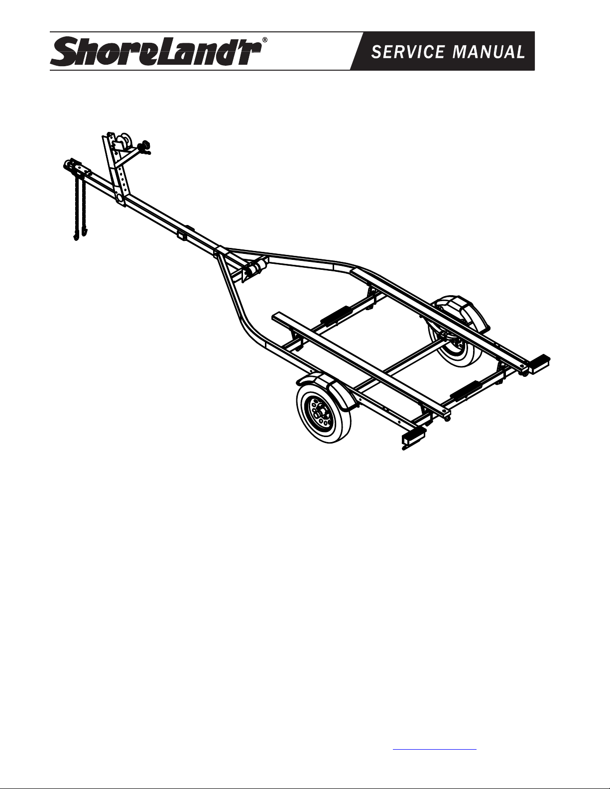
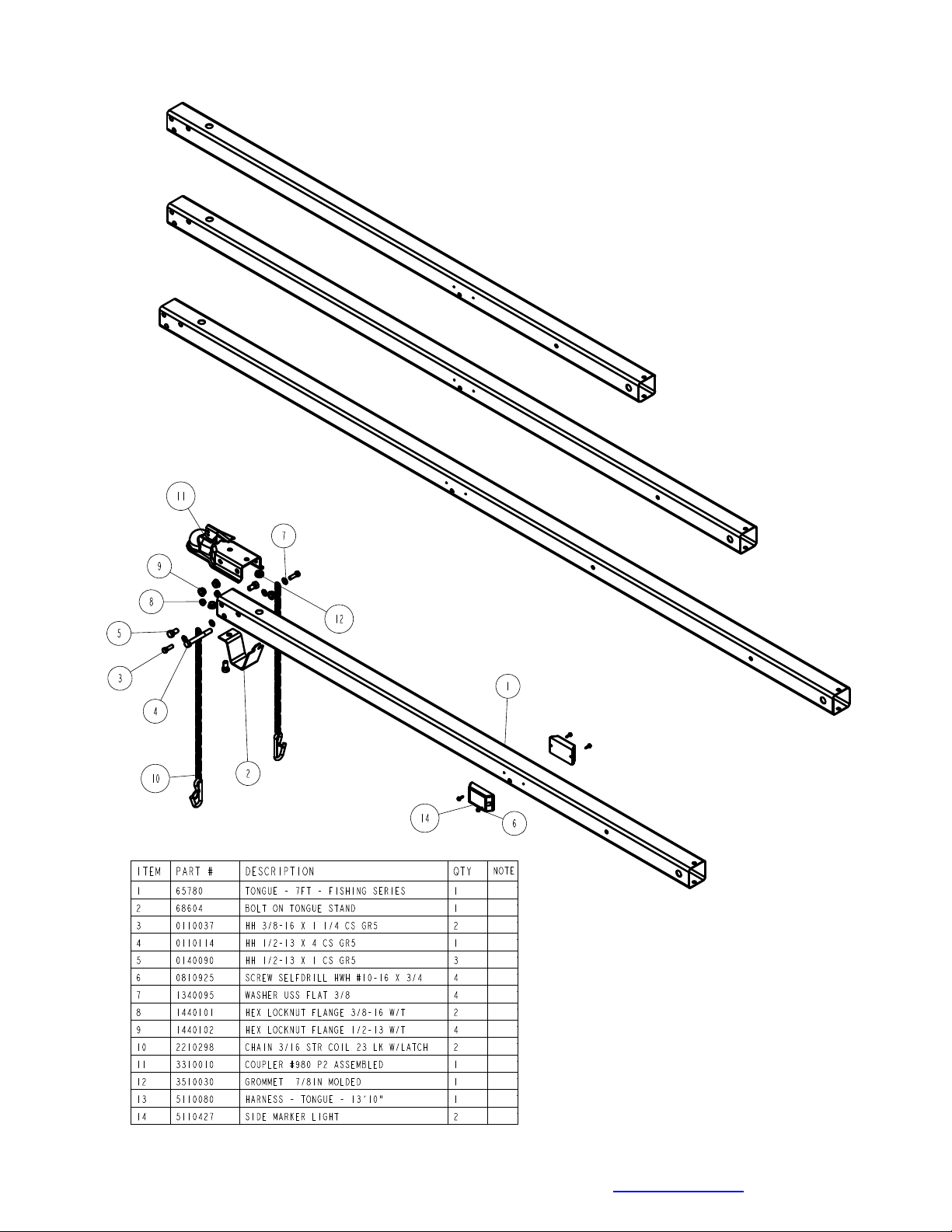
TONGUE ASSEMBLY
Place the frame to be assembled on saw horses or stands to assist in the assembly. Remove all items
that are banded to the frame. Sort the items in the hardware box by item and the hardware by size.
Locate the tongue for the trailer. Note that there are three different lengths of tongues designed to fit
this particular frame. The length of tongue will determine the length of boat that can be placed on the
trailer when assembled. The 7’ tongue will accommodate boats 12-14 feet in length, the 8’-6” tongue
will fit boats 14’ - 16’ 6” in length and the 10’ tongue is used for boats 15’ 6”- 18’ long.
Once the proper tongue is identified place it on the stands so it can be prepared for installation into the
frame. Locate the two amber side marker lights shipped in the hardware box. Uncoil the wire and insert
the plug end into the larger, center hole that is drilled in the side of the tongue. As the wire is inserted
into the hole direct the wire so that it will go to the forward end of the tongue. Pull the wire out the front
of the tongue. It will be connected to the tongue harness at a later time. Attach the light to the tongue
using two (2) No. 10 x 3/4” self-tapping screws provided. Repeat this process on the other light on the
other side of the tongue.
Locate the tongue wire harness. Insert the end of the harness with the small plug into the hole located
in the top of the tongue. Pull the wire backward through the tongue until the end comes out the rear of
the tongue. As the wire harness is inserted note that there are two single bullet wires towards the front
plug of the tongue wire harness. Pull these wires forward as the wire harness is inserted into the
tongue. Plug the single wires from the side marker lights installed earlier into the two single bullets of
the tongue harness. Push the additional back into the front of the tongue to keep it from damage during
use. Place a rubber grommet around the wire harness and in the hole in the top of the tongue to protect
the wires from damage during use.
Route the harness plug at the rear of the tongue through the hole provided in the side of the tongue.
Pull both the plug and the white ground wire out the hole. They will be attached later once the tongue is
installed in the frame.
Look at the bottom side of the tongue and locate the slotted key slot hole in the tongue. Note that one
end of the tongue stand has a dart or arrow shaped end. With the tongue stand positioned 90 degrees
to the centerline of the tongue, insert the dart or arrow end of the tongue stand into the key slotted hole.
Once it is inserted, turn the tongue stand 90 degrees so that it now is in line with the centerline of the
tongue. Attach the front end of the tongue stand to the tongue using a 1/2” x1” hex bolt and flange lock
nut. Tighten.
Locate the safety chains. Place a 3/8” flat washer on a 3/8” x 1-1/4” hex bolt. Insert the bolt through the
last link in the safety chain and then into the lower hole provided in the front of the tongue. Secure with
a 3/8” flange lock nut. Tighten. Repeat on the other chain.
Place the coupler on the top of the tongue. Align the holes in the coupler with the holes in the tongue.
Place a 1/2” x 4” hex bolt through the back holes of the coupler and the tongue. Secure with a 1/2”
flange lock nut but do not tighten at this point.
Place a 1/2” x 1” hex bolt through the front hole on one side of the coupler and the tongue so that the
head of the bolt is to the outside. Place a 1/2” flange lock nut on the bolt inside the tongue. Repeat this
process on the other side of the tongue. Once the bolts are installed, tighten all nuts left loose at this
time.
Insert the tongue assembly through the front channel of the frame far enough so the rear of the tongue
is inserted into the front cross member. Align the cross hole in the front channel and the tongue and
insert a 3/8” x 4” carriage bolt. Secure with a 3/8” flange locknut. Place a second 3/8” x 4” carriage bolt
down through the hole in the rear of the tongue and the front cross member. Place on a 3/8” flange lock
nut. Tighten.
Connect the tongue wire harness into the side frame harness of the trailer by matching plugs. Attach
the white ground wire of the tongue harness to the frame using a No. 10 x 3/4” self-tapping screw
provided so that a good ground connection is made between the frame of the trailer and the tow
vehicle. Push all extra wires used to make the connection back inside either the side frames of the
trailer or else into the tongue. Place a second rubber grommet into the hole where the wires exit the
tongue to protect them from damage during normal use.

Midwest Industries, Inc. Ida Grove, IA 51445 800-859-3028 www.shorelandr.com 0004224
Page 9 of 11 8/17/2010
Winch Post Assembly
The winch post assembly is pre-assembled and is shipped banded to the frame. See Diagram D. Place
the winch post on the tongue in the approximate location. Attach to the tongue using three (3) 3/8” x 4”
hex bolts and 3/8” flange lock nuts. It can be left loose until the boat is placed on the trailer for final
adjustment.
Place the winch handle on the drive shaft of the winch by mating the flat sides of the drive shaft with the
punched hole in the winch handle. Secure the handle to the drive shaft with the 1/2” lock nut provided.
Tighten.
Locate the bow eye safety chain in the hardware box. Place a 3/8” x 1” carriage bolt into the square
hole located in the small winch bracket as shown in Diagram D. The head of the bolt is to be on the top
of the bracket. Place the chain over the bolt just installed on the bottom side of the small winch bracket.
Secure to the small winch bracket with a 3/8” flat washer and flange lock nut. Tighten.
Axle and Wheel Assembly
Locate the axle for the trailer. Note that there isn’t a right or left to the axle assembly. Place one of the
springs on top of the spring pad welded to the axle as shown in Diagram D. Drop two (2) 3/8” x 2-3/16”
x 2” U-bolts over the springs and down through the holes in the spring pad. Secure with 3/8” flange lock
nuts. Repeat this process on the other spring mounting it so that it is oriented on the axle the same as
the first spring.
Slip a spring bushing spacer into the rear of the spring bracket, align the bushing with the hole in the
bracket and secure in position using a 1/2” x 3” hex bolt and 1/2” flange lock nut. Tighten. Repeat on
the other spring bracket.
Slide the axle assembly under the trailer frame, raise up and slide the rear of the springs above the
bushings just installed. Rotate the assembly up until the front spring eyes align with the front holes in
the spring bracket. Insert a 9/16” x 3-1/4” hex bolt and secure with a 9/16” lock nut. Tighten. Tighten the
U-bolt attaching the springs to the axles at this time and any other bolts that may have been left loose
for ease of assembly.
Place the tire and wheel assemblies on the hubs and secure with the 1/2” tapered lock nuts.
Tire and Wheel Assemblies
Mount the tire and wheel assemblies using the 1/2” fine threaded tapered lug nuts provided. Tighten to
80-90 ft/lb. of torque using the rotation pattern as shown in the ShoreLandr’s Owners Manual. Re-
torque the lug nuts after 50 miles of driving and then periodically thereafter.
Assembly is now complete and ready to be adjusted to fit the boat that it will carry.
Bunk Assemblies
Locate the fishing series bunk brackets supplied in the hardware box. Note that there are two right and
two left hand brackets. Refer to Diagram A for the proper placement of the right and left hand brackets.
Place a 3/8” x 3-7/16” x 2-1/2” U-bolt over the center cross member on the left side as shown with the
legs of the U-bolt pointing to the front of the trailer. Place one of the left fishing series bunk brackets
over the U-bolt just installed, then place on a 3/8” flat washer, 3/8” lock washer and hex nut on each leg
of the U-bolt. Hand tighten for now because they will have to be re-adjusted when the boat is placed on
the trailer. Repeat this process on the remaining left fishing series bunk bracket placing it on the rear
cross member.
Locate the 2 x 4 carpeted bunk assemblies. Note that they are pre-assembled. Position it as shown so
that the tie down bracket is located to the rear of the trailer.
Align the hole in the 2 x 4 bunk bracket already mounted to the bunk with the holes in the left fishing
series bunk brackets just installed. Attach the two together with a 3/8” x 1” hex bolt and flange lock nut.
Repeat the above process on the rear of the bunk. Tighten the bolts just installed but do not over
tighten because the bunks must be able to rotate to conform to the boat bottom when it is placed on the
trailer.

Midwest Industries, Inc. Ida Grove, IA 51445 800-859-3028 www.shorelandr.com 0004224
Page 10 of 11 8/17/2010
Repeat the above process on the bunk on the right side of the trailer. The bunk assembly is now
complete but may need to be adjusted once the boat is placed on the trailer.
Keel Roller Installation
Remove the keel roller assembly from the hardware box. Position it on the back side of the front cross
member of the frame as shown in Diagram A. Attach it to the cross member by placing a 1/2” star
washer on a 1/2” x 1-1/4” hex bolt. Align the slot in the keel roller bracket with the hole provided in the
cross member. Insert the bolt into the hole and attach to the cross member with a 1/2” lock washer and
hex nut. Repeat this process on the second bolt used to attach the keel roller assembly to the cross
member.
The keel roller assembly can be left loose until the boat is placed on the trailer for final adjustment.
Trailer Adjustments
Place the boat on the trailer so that the transom of the boat is positioned at the rear of the bunks.
Check the boat for clearance with the frame and tongue. Enough clearance is required between the two
so that the boat does not contact the frame during loading and unloading.
Bunk Adjustment
The bunk brackets are designed so that the U-bolts do not have to be removed to make the
adjustments. Loosen the nuts on the U-bolt enough so that the bracket can be moved. If the bunks
need to be raised higher rotate the bracket so that the legs of the U-bolt can be slid out of the current
slot for the raised position, then re-positioned into a new height location. Repeat this process on the
front of the bunk and then on the other bunk assembly. Once they are in the proper height position the
bunk assemblies can not be slid either in or out to properly fit your boat. For best loading the bunk
assemblies will be positioned just to the outside of a strake. This will help center the boat as it is
loaded.
Once the desired positioning is achieved tighten the nuts on the U-bolts securing the fishing series
bunk brackets to the cross members.
Keel Roller
Check the front of the boat for clearance between the frame and tongue. The keel roller has slotted
holes so they can be adjusted up or down to raise or lower to fit your boat. Once the boat is positioned
on the trailer as desired loosen the bolts and nuts attaching the keel roller to the cross member. Raise
the keel roller assembly up against the keel of the boat. Retighten in the new location. Note that the
boat will settle into the keel roller a little during normal use so it may be necessary to adjust them
slightly higher to compensate for this.
Winch Post
Once the boat is in the desired location and correct height on the trailer the winch post can now be
adjusted.
Slide the winch post on the tongue until it contacts the boat. Note that the bow eye roller on the winch
post must be positioned directly above the boat bow eye. This location is necessary to prevent the boat
from sliding forward during normal use as well as in the event of a sudden stop. This positioning will
also allow the winch strap to pull directly from the winch into the bow eye for better retention. Change
the bow stop height by removing the bolts attaching it to the winch post. Relocate to the proper height
and refasten with the bolts just removed.
Once the winch post is set secure, the winch post to the tongue with the three mounting bolts used to
attach it to the tongue.
Place the bow eye safety chain in the bow eye of the boat as a secondary means of keeping the boat
attached to the trailer in the event of a winch, winch strap or hook failure.
The axle is adjustable on this model trailer so that the proper tongue weight can be achieved. To
change the tongue weight, remove the four 3/8” x 2-3/4” hex bolts attaching the spring brackets and

Midwest Industries, Inc. Ida Grove, IA 51445 800-859-3028 www.shorelandr.com 0004224
Page 11 of 11 8/17/2010
fender to the trailer frame. The axle can then be moved forward or backward to get the proper tongue
weight.
A recommended tongue weight for your trailer is 7-10% of the total load including boat, motor, and
trailer.
Adjustments are now complete. Double check your boat for fit. If desired fit has been achieved, tighten
all fasteners that may have either been left loose or have been loosened to do the adjusting.
Note: All nuts and bolts must be tightened before towing.
The law requires that the white ground wire on both the tongue wire harness and vehicle
harness be properly grounded to respective trailer and vehicle frames.
Re-check all fasteners on the complete trailer to make sure they are all tight and ready for towing. All
fasteners should be periodically checked before towing.
See your ShoreLand’r Owner’s Guide for further technical information regarding your trailer and its
components.
This manual suits for next models
2
Table of contents
Other ShoreLand'r Utility Vehicle manuals
Popular Utility Vehicle manuals by other brands

Toro
Toro 07383 Operator's manual

Massimo
Massimo 500UTV owner's manual

Federal Signal Corporation
Federal Signal Corporation LEACH 2R-III Service manual

PARKIT360
PARKIT360 FORCE 5K manual

NC ENGINEERING
NC ENGINEERING MKII 600 Series Operating, maintenance and safety instructions

Bomag
Bomag BMP 8500 Operating and maintenance instructions