Midwest Industries, Inc. Ida Grove, IA 51445 800.859.3028 www.shorelandr.com 0003555
Page 8
Place the spring and axle U-bolt plate onto the ends of the two U-
bolts just placed. Secure in place with 1/2” lock nuts. Thread onto
the U-bolts but do not tighten securely until the complete unit is in
position on the trailer. Repeat on the other spring.
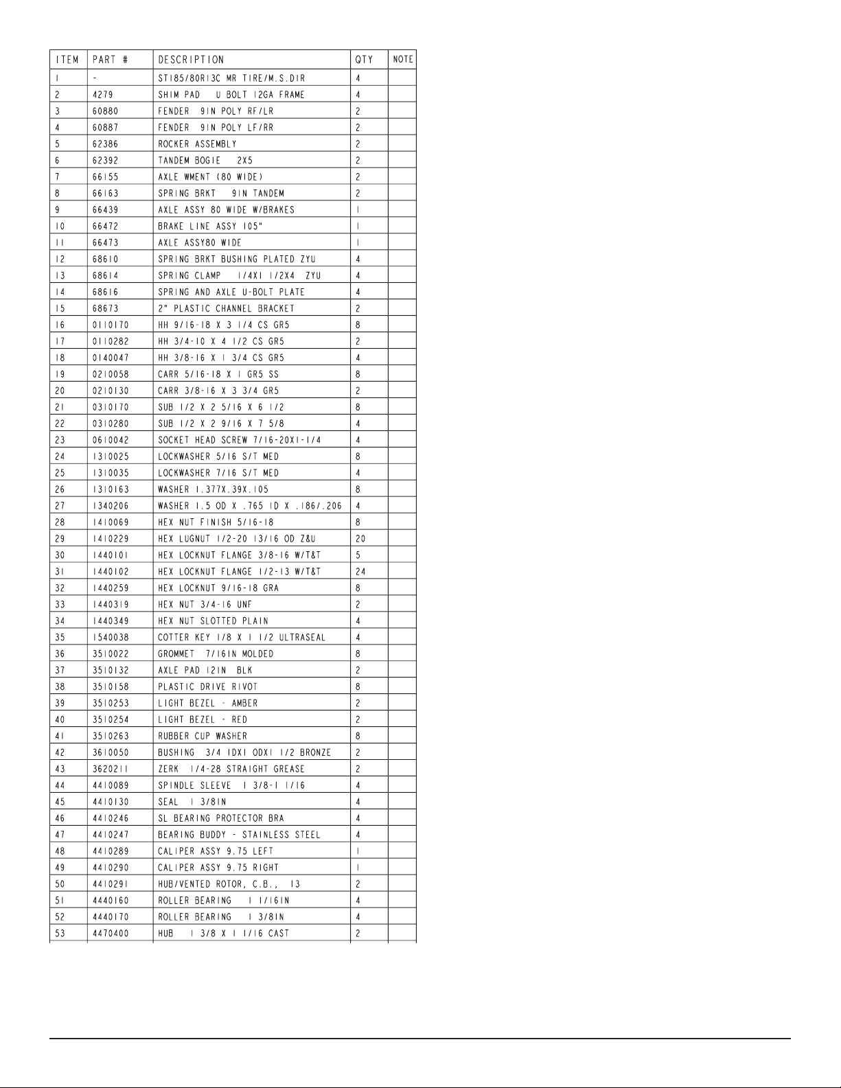
AXLE
Place one of the spring bracket bushings into the rear of the spring
bracket and secure with a 9/16” x 3-1/4” hex bolt and hex lock nut.
Repeat in other spring bracket. Position the rear axle under the
frame, then hook the loop of the springs around the bushings just
installed. Note that if the axle is positioned too low when trying to
hook, the loops will not hook around the bushings.
Raise the front of the springs up so they align with the rear hole in
the axle boogie just installed. Secure in place with 9/16” x 3-1/4”
hex bolts and lock nuts.
Install another spring bracket bushing in the front hole on the rock
arm assemblies. Secure with a 9/16” x 3-1/4” hex bolt and lock nut.
Tighten.
Hook the hook end of the springs mounted to the front axle over the
bushing just installed in the rocker arm assembly. Swing the front
of the spring up and attach the front mounting hole in the spring
bracket with another 9/16” x 3-1/4” hex bolt and lock nut.
Tighten all axle U-bolts and spring bolts.
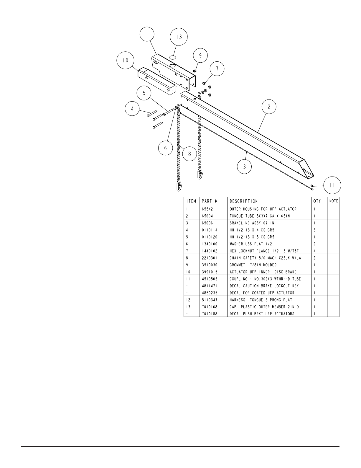
ONE AXLE BRAKE INSTALLATION
Cut the tape securing the brake line hose to the axle. Remove the
brass plug from the port in the brass block on the right brake cali-
per. Thread in the brake hose male end and tighten to either 6-8 ft.
lb. or 72-96 in. lb. of torque.
DO NOT OVER TIGHTEN Over tightening will cause
the brass block to crack and then leak.
Place the other end of the hose up through the hole provided in the
brake line clip bracket. Secure in place with the U-shaped hose clip
provided.
Remove the plastic cap from the end of the frame brake line com-
ing out of the side frame by the axle. Carefully uncoil the brake line
so that it will reach the end of the hose just attached to the brake
line bracket. Thread the brake line fitting into the brake line hose.
Tighten.
NOTE: The axle has brake fluid installed in the calipers and the
axle line when it is assembled at the factory. This is done to protect
the inner parts of the brake system during shipping and storage.
The complete brake system including the axle MUST be re-bled to
ensure that all air has been removed from the brake system.
For bleeding instructions see the UFP brake bleeding manual or
the ShoreLand’r Disc Brake Manual.
Fill the actuator reservoir with brake fluid and bleed the line per the
instructions in the Brake Manual.
TIRE & WHEEL ASSEMBLY
Mount the tire and wheel assemblies using the 1/2” fine threaded
tapered lug nuts provided. Tighten to 85-95 ft./lb. torque using the
rotation pattern as shown in the ShoreLandr’s Owners Manual.
Re-torque the lug nuts after 50 miles driving and then periodically
thereafter.
TRAILER ADJUSTMENTS
The adjustment of the trailer to your boat is very important not only
for the trailer, but also the boat. Failure to do so may lead to poten-
tial failure or damage to either the trailer or boat.
Adjust as follows:
AXLE ADJUSTMENT
The amount of tongue weight on your trailer can be adjusted as
follows:
To lower the tongue weight, adjust the axle assembly forward. To
increase the tongue weight, adjust the axle backward.
The distance that the axle assembly has to be moved will vary be-
cause it is directly related to the weight and center of gravity of the
boat placed on it.
Best towing is achieved when the tongue weight is 5-7% of the total
gross load of the complete unit.
Note: Wire harnesses and brake line lines will need care when
moving the axle assembly.
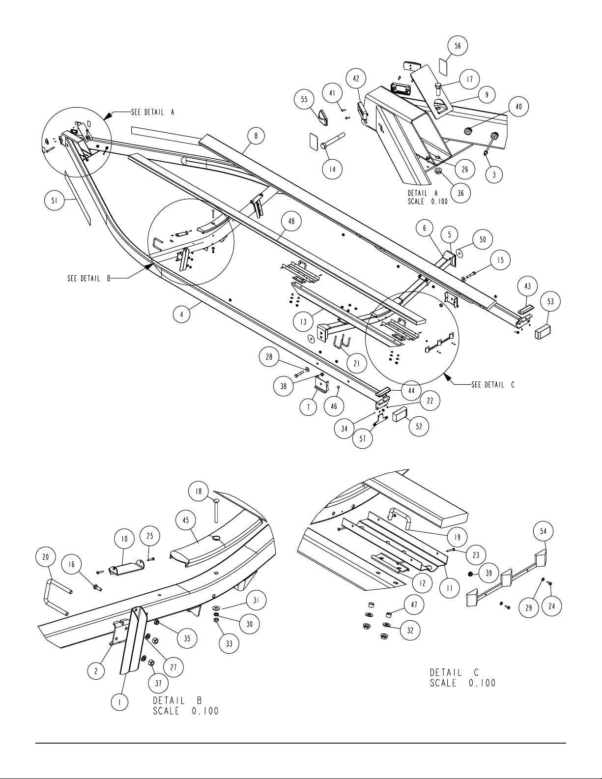
REAR SUPPORT SYSTEM
Place the boat on the trailer so that the transom is located at the
rear of the support system. On a bunk trailer, the transom of the
boat should be within 1-2” of the end of the bunk. This gives you
maximum support on the transom.
The rear cross member is adjustable forward or backward to allow
the trailer to be adjusted to various length boats. This is accom-
plished by removing the pivot bolt on holds each end of the rear
pivot to the side frame. Reposition the rear pivot arm into the other
hole position predrilled in the side frame.
Reattach the rear pivot to the side frame with the bolts just re-
moved. Tighten.
The wire harness for the three-light identification light must be re-
positioned where it comes from the side frame to the rear pivot to
eliminate slack, and sagging of the wiring.
BUNKS
Make sure the bunks are positioned far enough apart to give your
boat as much stability as possible while transporting. Position the
bunks so they are located just the outside of a strake that your boat
may have. This will help center your boat and assist when loading.
The bunks need be adjusted up high enough to keep the keel from
resting on the center pads. A minimum of one to two inches clear-
ance is desirable.
FRONT BUNK SUPPORT
The front bunks should be adjusted either in or out so that the bunk
will continue to run just to the outside of the strake of the boat.
Adjust the bunks up so that there is approximately 1-2 inches clear-
ance between the keel of the boat and the center cross member
pad.
WINCH POST
Once all other adjustments are complete, the winch post can be
adjusted. Slide the winch post backward on the tongue until the
bow stop roller comes in contact with the boat. This bow roller must
be positioned directly above the bow eye to prevent your boat from
moving forward in the event of a sudden stop. The bow roller as-
sembly can be moved up or down by loosening the three ½” bolt