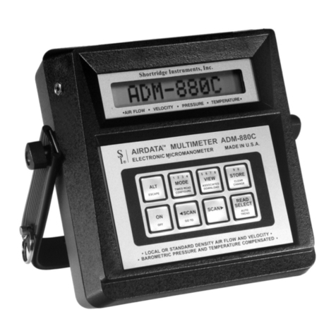
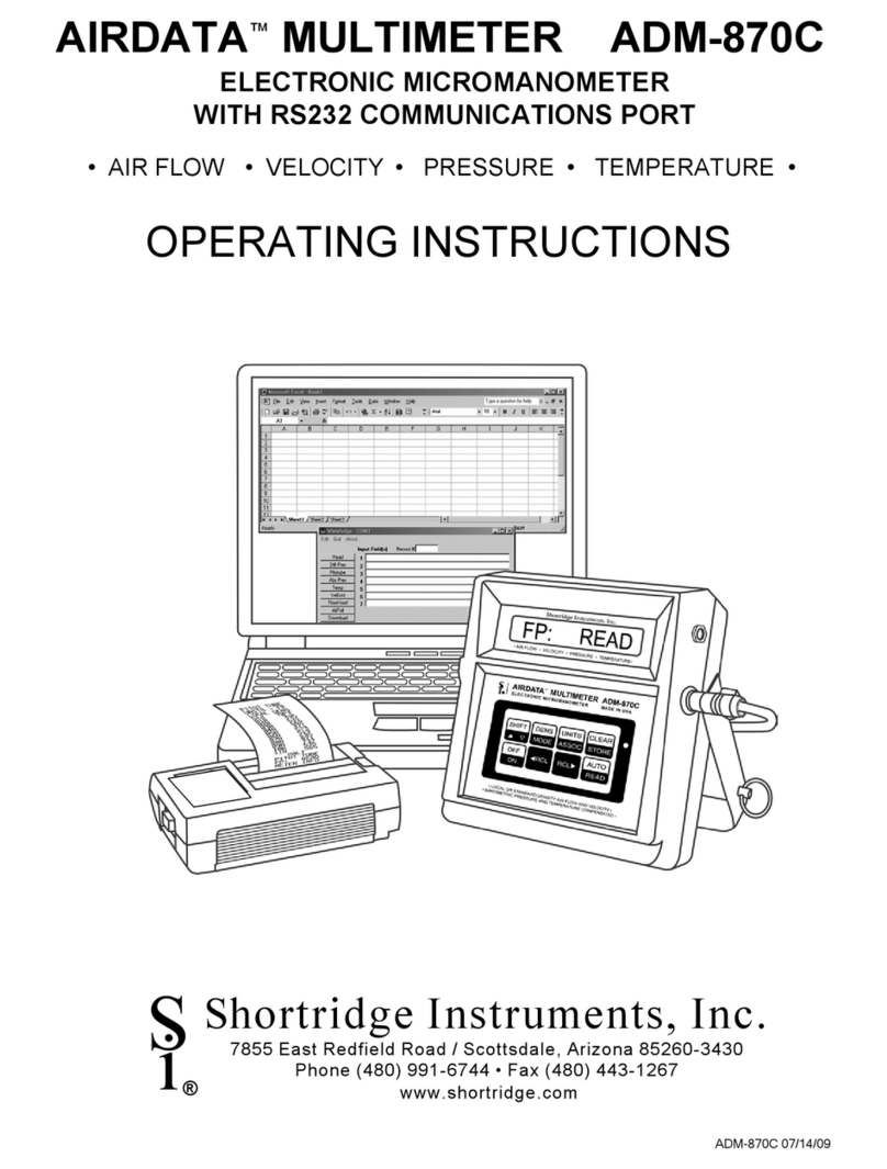
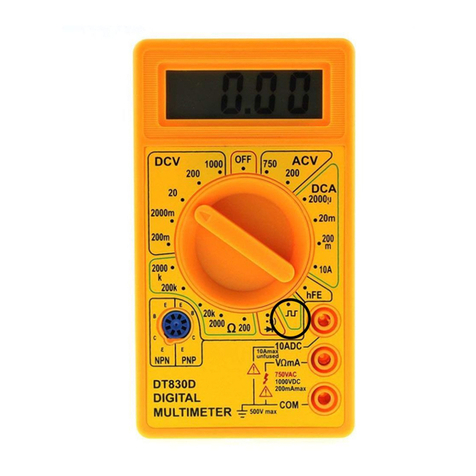
Shortridge Instruments Airdata ADM-870 User manual

ADM-870 05/23/08
Shortridge Instruments, Inc.
7855 East Redfield Road / Scottsdale, Arizona 85260-3430
Phone (480) 991-6744 • Fax (480) 443-1267
www.shortridge.com
S
i
AIRDATA™MULTIMETER ADM-870
ELECTRONIC MICROMANOMETER
AIR FLOW • VELOCITY • PRESSURE • TEMPERATURE
OPERATING INSTRUCTIONS
®

ADM-870 05/23/08i
CONTENTS
1.0 INTRODUCTION 1
2.0 SPECIFICATIONS 2
3.0 EXTERNAL FEATURES 4
3.1 KEYPAD 4
3.2 FEATURES ON SIDES AND BACK OF METER 4
4.0 DISPLAY MESSAGES AND PROMPTS 7
4.1 READ PROMPTS 7
4.2 MEASUREMENT READOUTS 7
4.3 FUNCTION READOUTS 8
5.0 USING THE AIRDATA MULTIMETER 12
5.1 AUTOMATIC READINGS 12
5.2 MEMORY/AVERAGE/TOTAL FUNCTION 12
5.2.1 MEMORY OPERATION 12
5.2.2 RECALL 13
5.2.3 DISCARD READING 13
5.2.4 CLEAR MEMORY 13
5.2.5 ERROR 13
5.3 AUTOMATIC READING MEMORY 13
5.4 SPEED-READ FEATURE 13
5.4.1 SPEED-READ OPERATION 14
6.0 VELOCITY MEASUREMENT 15
6.1 VELOCITY CORRECTION FACTORS 15
6.2 PITOT TUBE VELOCITY MEASUREMENT 16
6.3 AIRFOIL PROBE 17
6.3.1 DUCT VELOCITY USING AIRFOIL PROBE 18
6.3.2 FUME HOODS AND SAFETY CABINETS - AIRFOIL 18
6.3.3 EXHAUST HOODS - AIRFOIL PROBE 19
6.3.4 LAMINAR FLOW WORKSTATIONS - AIRFOIL PROBE 19
6.4 VELGRID AIR VELOCITY 19
6.4.1 CHEMICAL EXHAUST HOODS - VELGRID 20
6.4.2 LAMINAR FLOW WORKSTATION - VELGRID 20
6.4.3 AIR FLOW CALCULATION FROM VELGRID VELOCITY 20
6.5 VELOCITY: LOCAL DENSITY VS STANDARD DENSITY (MASS FLOW) 22
7.0 PRESSURE MEASUREMENT 23
7.1 DIFFERENTIAL PRESSURE 23
7.1.2 PITOT TUBE "VELOCITY PRESSURES" 23
7.1.3 PITOT TUBE "STATIC PRESSURES" 23
7.1.4 PITOT TUBE "TOTAL PRESSURES" 24
7.2 ABSOLUTE PRESSURES 24
8.0 TEMPERATURE MEASUREMENT 25
8.1 TEMPROBE 25
8.2 AIRDATA MULTITEMP 25
9.0 AIR FLOW MEASUREMENT 27
9.1 FLOWHOOD FUNCTION 27
9.2 BACKPRESSURE COMPENSATION 27
10.0 FLOWHOOD ASSEMBLY 28
10.1 UNPACKING 28
10.2 FRAME CHANNELS 28
10.3 FABRIC TOPS 28
10.4 SUPPORT ASSEMBLY 28
10.5 HANDLE 29
11.0 FLOWHOOD OPERATING PROCEDURE 34
11.1 AIR FLOW - NONBACKPRESSURE COMPENSATED READINGS 34
11.2 AIR FLOW - BACKPRESSURE COMPENSATED READINGS 34
11.2.1 ERROR 35

ADM-870 05/23/08ii
12.0 SPECIAL BALANCING PROCEDURES 36
12.1 PROPORTIONAL BALANCING 36
12.2 LARGE RETURN AIR GRILLES 36
12.3 KITCHEN EXHAUST HOODS 36
12.3.1 RANGE EXHAUST FILTERS AND GREASE EXTRACTORS 36
12.4 CONSTANT VOLUME CONTROLLERS 36
12.5 LINEAR SLOT DIFFUSERS 37
12.6 SIDEWALL REGISTERS 37
12.7 14"x14"x14" SHORT TOP SET 37
12.8 SYSTEM PROBLEMS 37
13.0 CORRECTION FACTORS AND CONVERSION FORMULAS 38
13.1 BAROMETRIC PRESSURE DENSITY CORRECTION - LOCAL DENSITY 38
13.2 TEMPERATURE DENSITY CORRECTION 38
13.4 RELATIVE HUMIDITY CORRECTION 38
13.5 HOT WIRE ANEMOMETER VERSUS AIRDATA MULTIMETER 38
14.0 METER ACCURACY FIELD TESTING 40
14.1 METER ZERO FUNCTION 40
14.2 DIFFERENTIAL PRESSURE FUNCTION 40
14.3 ABSOLUTE PRESSURE FUNCTION 40
14.4 AIR FLOW ACCURACY 40
14.5 DUCT TRAVERSE COMPARISONS, INCLINED MANOMETER, MICROMANOMETER 40
14.6 DUCT TRAVERSE USING THE AIRDATA MULTIMETER 41
14.7 BACKPRESSURE COMPENSATED COMPARISON READINGS 41
14.8 NONBACKPRESSURE COMPENSATED COMPARISON READINGS 41
15.0 METER & FLOWHOOD MAINTENANCE 42
15.1 METER MAINTENANCE 42
15.2 FLOWHOOD MAINTENANCE 42
16.0 RECALIBRATION AND REPAIR INFORMATION 43
AIR BALANCE MANUALS & TRAINING PROGRAMS 43
WARRANTY 44
APPENDIX A - NIST VELOCITY TESTING 45
APPENDIX B - LABORATORY DIFFERENTIAL PRESSURE TEST 46
APPENDIX C - BATTERY TEST PROCEDURE 47
REPLACEMENT PARTS LIST 49
ADM-870 INDEX 51
Copyright © Shortridge Instruments, Inc., 2008. All rights reserved. This information may
not be reproduced or duplicated in any manner, or for any purpose, without
permission in writing from Shortridge Instruments, Inc.

ADM-870 05/23/08iii
ILLUSTRATIONS
3.1 ADM-870 METER FRONT AND BACK 6
6.1 PITOT TUBE 17
6.2 AIRFOIL PROBE 18
6.4 VELGRID ASSEMBLY 21
7.1 STATIC PRESSURE PROBE 23
8.1 ADT442 TEMPROBE 25
8.2 AIRDATA MULTITEMP 26
10.1 FRAME STORAGE 30
10.2 FLOWHOOD IN CASE 30
10.3 FLOWHOOD ASSEMBLY 31
10.4 2X2 FRAME ASSEMBLY 32
10.5 1X4 FRAME ASSEMBLY 32
10.6 2X4 FRAME ASSEMBLY 32
10.7 1X5 FRAME ASSEMBLY 33
10.8 3X3 FRAME ASSEMBLY 33

ADM-870 05/23/081
1.0 INTRODUCTION
You will find these instructions much easier to follow if you have the meter in front of you as you read through
them. You can note the various connections and press the keys, observing the displayed results as you read
through the various procedures. The operation of the meter is quite simple and straightforward, as will
become apparent after a little practice.
The AirData Multimeter performs the following essential functions. This meter measures air velocity when
used with a pitot tube, AirFoil probe, or VelGrid and automatically corrects for density variations due to local
temperature and barometric pressure. Velocity ranges are 0-29,000 fpm using a pitot tube, 0-5,000 fpm using
the AirFoil probe, and 0-2500 fpm using the VelGrid.
When used with the Series 8400 FlowHood System, this unit measures air flow and may compensate for
density and backpressure effects, allowing direct air flow readings from 0-2500 cfm. Accurate differential
pressure measurements can be obtained from 0.0001 in wc to 60.00 in wc. Absolute pressure measurements
range from 10-40 in Hg. Temperatures can be measured from -67/F to 250/F, either individually, or in
conjunction with an air flow or velocity measurement.
The Model ADM-870 AirData Multimeter performs these additional functions which greatly simplify the
complex technical requirements of highly demanding test and balance projects. This model features an
automatic mode which registers repeated measurements for any capability, with sequential storage and recall
of up to 100 automatically or individually obtained measurements, with sequence tags for each value. Recall
of the sum and average of the stored sequence is available at any point, without terminating the process.
Flow and velocity measurements may be displayed in either local air density or the standard density (mass
flow) sea level equivalent.
Internal calibration and zeroing of the AirData Multimeter are fully automatic. No external adjustments are
ever needed. This instrument is extremely tolerant of overpressure, and is unaffected by position or by
ambient temperatures from 40/F to 140/F.
It is recommended that the AirData Multimeter kit be returned to the factory at least every two years for
recalibration and software update. This preventive maintenance program will assure that the original accuracy
of the meter is maintained throughout the life of the meter.

ADM-870 05/23/082
2.0 SPECIFICATIONS
AIR VELOCITY: Measured in feet per minute (fpm), or meters per second (m/s), corrected for local or
standard air density. The measurement range is 25 to 29,000 fpm with a pitot tube, and 25 to 5,000 fpm with
the Shortridge Instruments, Inc. AirFoil probe. The measurement range using the VelGrid is 25 to 2500 fpm.
Accuracy is ± 3% of reading ± 7 fpm from 50 to 8000 fpm. Pitot tube velocity readings from 8,000 fpm to
29,000 fpm are based on compressible isentropic flow theory and are not certified NIST traceable.
DIFFERENTIAL PRESSURE: Measured in inches of water column (in wc) or Pascals (Pa). The
measurement range is from 0.0001 to 60.00 in wc. Maximum safe pressures are 20 psid (900% full scale)
and 60 psia common mode. Accuracy is ± 2% of reading ± 0.001 in wc from 0.0500 to 50.00 in wc.
ABSOLUTE PRESSURE: Measured in inches of mercury (in Hg) or bars with reference to a vacuum. The
measurement range is 10-40 in Hg. Maximum safe pressure is 60 psia. Accuracy is ± 2% of reading ±
0.1 in Hg from 14 to 40 in Hg.
TEMPERATURE: Accuracy is ± 0.5/F from 32/F to 158/F with a resolution of 0.1/F using the ADT442,
ADT443, ADT444, ADT445 or ADT446 TemProbes. Meter will display readings from -67.0/F to 250.0/
F. Safe exposure range for TemProbe is -100/F to 250/F. Do not expose the plastic base of the
TemProbe or the extension wand to temperatures above 200/F.
AIR FLOW: Measured in cubic feet per minute (cfm) or litres per second (L/s), corrected for air density. This
function requires the use of the Shortridge Instruments' Series 8400 Backpressure Compensating
FlowHood System. The measurement range is 25 to 2500 cfm supply and 25 to 1500 cfm exhaust.
Accuracy is ± 3% of reading ± 7 cfm from 100 to 2000 cfm (nonbackpressure compensated readings).
AIR DENSITY CORRECTION: The air density correction range is 14-40 in Hg and 32/F to 158/F for
correction of air flow and velocity measurements. The readings represent either local density air flow or
standard density sea level equivalent (mass flow) for air flow or velocity. Readings are corrected for the
density effects of temperature and absolute pressure.
MEMORY: 100 readings with sequential recall of each reading with average and sum.
RESPONSE TIME: Five seconds or less at pressures greater than .002 in wc (180 fpm), and up to eight
seconds at less than .0003 in wc (70 fpm). SPEED-READ mode provides continuous readings in as little
as two second intervals. (Accuracy specifications do not apply).
READOUT: Eight digit, 0.5 inch, liquid crystal display (LCD).
METER HOUSING: High impact, molded, "T" grade ABS.
WEIGHT: 36 ounces, (1.02 kg) including batteries.
SIZE: 6.0" x 6.4" x 2.7" (15.2 x 16.3 x 6.9 cm).
BATTERY LIFE: Normally two working days of heavy use, or 2000 readings per charge. A set of
rechargeable type AA NiCad batteries is supplied in each meter. Batteries may be recharged up to 500
times before replacement. If rechargeable batteries are not available in a field situation, the batteries may
be replaced with 12 non-rechargeable "AA" pen cell batteries. WARNING: Do not plug the charger in
if any non-rechargeable batteries are in the meter. The meter may be seriously damaged along with the
batteries and charger.
BATTERY CHARGER: The battery charger requires 120V, 60Hz, 6W. Batteries recharge in a maximum of
10 hours, and may be left on charge for an unlimited time without harm. The temperature of the
instrument during charge should be kept between 40/F and 113/F (5/C to 45/C). The meter is fully
operational during recharge.
OPERATIONAL TEMPERATURE LIMITS: The specified accuracy for measurements is maintained over a
meter exposure temperature range of 40/F to 140/F (5/C to 60/C).
STORAGE TEMPERATURE LIMITS: -4/F to 140/F (-20/C to 60/C).

ADM-870 05/23/083
AIR BLEED: Each pressure measurement allows a small volume of air to pass through the meter. The
pressure source must be capable of supplying this volume without significant depletion to assure accurate
measurements. Bleedthrough (typ) 0.0004 cu in/in wc/measurement. Quiescent bleedthrough (max)
0.0005 cu in/in wc/minute.
TUBING: The maximum recommended length of pneumatic tubing for the measurement of air flow, velocity,
or differential pressure is 18 feet. Minimum tubing size is 3/16 inch internal diameter. The VelGrid is used
with the two eight foot lengths of 3/16 inch ID tubing furnished with the kit.

ADM-870 05/23/084
3.0 EXTERNAL FEATURES
3.1 KEYPAD
The meter keypad has eight keys. Each key may include multiple functions that may be activated, either
alternately, or by pressing the shift key followed by the function key. The instructions will often refer to
a key by only one of the functions shown on the key.
A. Upper half of keys SILVER - active only after pressing "SHIFT" key.
Control name Function
SHIFT Shifts control from lower to upper half of keys and vice versa.
UNITS Alternate action for English or metric units.
DENS Alternate action for local or standard density.
CLEAR Clears memory, auto-read and average functions.
OFF Turns the meter off.
AUTO Automatic repeat reading.
B. Lower half of keys BLACK - always active except following SHIFT.
Control Name Function
MODE Sequential action for all measurement modes (air flow, velocity, pressure and
temperature).
ASSOC Recalls associated temperature and pressure for flow and velocity
STORE Activates memory mode, then alternate action for average and for total. (This key was
labeled "MEM" prior to May, 1993).
ON Turns the meter on.
=RCL Recalls stored readings in reverse order.
RCL <Recalls stored readings in entry order.
READ Initiate measurement, and SPEED-READ or halt automatic readings.
3.2 FEATURES ON SIDES AND BACK OF METER
BATTERY CHARGER JACK
When viewed from the front, the battery charger jack is on the right side of the meter toward the top. The
battery charger plug is to be connected here.
EXTERNAL READ JACK
When viewed from the front, the external read jack is on the left side of the meter toward the top. The
plug for the external thumbswitch is connected here. This feature allows the operator to trigger air flow
measurements from the FlowHood or VelGrid handgrip while working overhead or in awkward
circumstances. The thumbswitch performs exactly the same function as the READ key.
FLAPS JACK
The flaps jack is on the back of the meter, in the upper right hand corner. The flaps plug on the FlowHood
is connected here.
TEMPERATURE INPUT JACK
The temperature input jack is centered on the back of the meter, slightly toward the top. The flexible

ADM-870 05/23/085
TemProbe sensor must be connected to this receptacle whenever temperature density correction is
desired for either flow or velocity measurements. A retractile cord connects the TemProbe or the
MultiTemp to the temperature input jack for remote temperature sensing.
OFF/RESET SWITCH
The off/reset pushbutton switch is on the back of the meter in a recess near the upper left corner. This
switch is used to reset the meter in the unlikely event that the microprocessor becomes lost in its program.
This may occur if the meter is dropped, and may cause the keypad to become nonfunctional until the
meter is reset. If the meter continues to fall into "lockout", it may have been damaged, and should be
returned for repair.
PNEUMATIC PRESSURE INLETS
Two pneumatic pressure inlets positive (+) and negative (-) are centered on the back of the meter at the
top edge and may be connected to various pressure sources for the measurement of air velocity, flow,
or pressure. Sources include the FlowHood, AirFoil probe, VelGrid, pitot tubes, static pressure probes,
or any other pressure source not exceeding the safe limits for the meter. The negative (-) inlet senses
the static pressure during flow or velocity measurements, and also is used for direct absolute pressure
measurements.

ADM-870 05/23/086
External Read Jack for
Pushbutton Handle Plug
Pushbutton Reset Switch
8 Digit, 0.5" LCD Display
SHIFT Activates Upper Half of Keys
Battery Charger Jack
DENS Local Density/Standard Density
MODE Flow/Pres/Temp/VLG/AFP/Pitot/Abs
UNITS English/Metric
ASSOC Associated Pressure & Temperature
CLEAR Clear for Memory and Speed-Read
STORE Memory/Average/Total
AUTO Automatic Readings
READ Read/Hold for Speed or Halt
RCL <Recall in Entry Order
=RCL Recall in Reverse Order
OFF Power Off
ON Power On
Positive (+) Pressure Port
Negative (-) Pressure Port
Flaps Jack for FlowHood Flaps Plug
Threaded Insert for Attachment to FlowHood with
Captive Screw
Calibration Label with Serial Number & Date
Temperature Input Jack for TemProbe,
Retractile Cord or MultiTemp
Battery Compartment Cover - Remove the 8 Small
Phillips Head Screws to Test or Replace the
Batteries (12 AA NICAD)
Four Large Phillips Head Screws That Hold
the Meter Case Together - DO NOT REMOVE
FIGURE 3.1 ADM-870 METER FRONT AND BACK

ADM-870 05/23/087
4.0 DISPLAY MESSAGES AND PROMPTS
4.1 READ PROMPTS
The following ten prompts all include the term READ, which is a signal for the operator to press the READ key
to trigger the actual measurement.
English Units
CF: READ
This display indicates that the meter has been placed in the air flow function (cfm) and will appear
automatically upon power up if the flaps plug of the FlowHood is connected to the meter.
/F: READ
This display indicates that the meter has been placed in the temperature function (/F).
FP: READ
This display indicates that the meter has been placed in a velocity function (fpm).
Hg: READ
This display indicates that the meter has been placed in the absolute pressure function (in Hg) with
reference to a vacuum.
IN: READ
This display indicates that the meter has been placed in the differential pressure function (in wc).
Metric Units
BAR READ
This display indicates that the absolute pressure readings will be displayed in bars (1 bar = 100 kPa) with
reference to a vacuum.
/C: READ
Display indicates that the temperature readings will be displayed in degrees Celsius /C).
LS: READ
This display indicates that the meter has been placed in the air flow function and will read in litres per
second (L/s).
/S: READ
This display indicates that the velocity readings will be displayed in meters per second (m/s).
PA: READ
This display indicates that differential pressure readings will be displayed in Pascals (Pa).
4.2 MEASUREMENT READOUTS
In the following 12 examples, n indicates a number in the displayed result. If no sign is displayed, the result is
a positive number. A negative sign indicates a negative number. English and metric units are shown for each
example.
English Units
CF:c± nnnn
Indicates that the result represents an air flow measurement (cfm). "C" indicates that the result has been
compensated for backpressure effects.
CF:u± nnnn
Indicates that the result represents an air flow measurement (cfm). "U" indicates that the result has not
been compensated for backpressure effects.
FP: ± nnnnnn
Indicates that the displayed result represents a velocity measurement (fpm).
/F: ± nnn.n
Indicates that the displayed result represents a temperature measurement (/F).
Hg: ± nn.n
Indicates that the result represents an absolute pressure measurement (in Hg).

ADM-870 05/23/088
IN: ± nnnnn
Indicates that the result represents a differential pressure measurement (in wc).
Metric Units
BAR n.nnn
Indicates that the result represents an absolute pressure measurement (bar). (One bar = 100 kPa).
/C: ± nnn.n
Indicates that the displayed result represents a temperature measurement (/C).
LS:c± nnnn
Indicates that the result represents an air flow measurement (L/s). "C" indicates that the result has been
compensated for backpressure effects.
LS:u± nnnn
Indicates that the result represents an air flow measurement (L/S). "U" indicates that the result has not been
compensated for backpressure effects.
PA: ± nnnnn
Indicates that the result represents a differential pressure measurement (Pa).
/S: ± nnnnnn
Indicates that the displayed result represents a velocity measurement (m/s).
4.3 FUNCTION READOUTS
The following prompts and messages are listed in alphabetical order.
8.8:8.8.8.8.8.8
A sequence of eights will be flashed briefly to test the operation of the display each time the meter is turned
on.
ABS PRES
This signal will be flashed when the absolute pressure mode is selected, and also each time the READ key
is pressed when in the absolute pressure mode.
AIRFOIL
This signal will be flashed when the AirFoil probe mode is selected and also upon each subsequent
operation of the READ key.
AUTOSTOR
This message indicates that the meter has been placed in the automatic memory mode, which integrates
the automatic reading function with the sequential storage function, and permits recall of the readings, sum
or average at any point. Press the READ key to initiate the actual reading process. Press and hold the
READ key until HALT is displayed in order to stop the automatic reading sequence.
AUTO RDY
This message indicates that the meter has been placed in the automatic reading function. Press the READ
key to initiate the actual measurement and hold the READ key down to halt the process.
CAL
When the meter is first turned ON, it will perform a self-calibration process that takes a few seconds. The
display will read CAL during this period and the operating controls will be inhibited. No READ operations
or function changes may be made during the CAL period. The meter will also perform a brief CAL cycle
about once every thirty seconds throughout normal operation.
CALC
This message indicates that the measurement sampling period has been completed, and that the
calculations are in process. When CALC has been displayed, the sensors, or the FlowHood, may be
removed from the measurement position without affecting the result.
CF: CORR
This message indicates that the air flow measurement being performed will be backpressure compensated.

ADM-870 05/23/089
CF: UNCORR
This message indicates that the air flow measurement being performed will not be backpressure
compensated.
CLEAR
This signal is flashed as the memory, auto, or SPEED-READ function is cleared.
DIF PRES
This signal will be flashed when the differential pressure mode is selected, and also upon each subsequent
operation of the READ key.
ENGLISH
This message indicates that the readings will be in English units. Pressing the SHIFT key and then the
UNITS key will switch the meter to metric units. The meter automatically starts up in English units when first
turned on. Metric startup is available if requested.
ERROR
This message advises the operator that the backpressure compensated air flow measurement, which is in
process, is invalid because the numerical ratio of the two parts of the measurement sequence exceeds the
predetermined limits. Normally this means, either that the operator has made a procedural error, or that a
dynamic change (such as a changed damper setting) has occurred between the two parts of the
backpressure compensated air flow measurement process. ERROR will also be displayed during a memory
sequence, either manual or automatic, that has been interrupted by an alteration in the meter set up, such
as the connection of the flaps plug or temperature probe.
FLO-HOOD
This message will be flashed when the FlowHood mode is selected, or when the meter is first turned on if
the flaps plug is connected.
HALT
This message will be displayed when an automatic reading sequence has been halted manually by holding
down the READ key. The individual readings, or the average and total of the readings, may now be
displayed if the memory mode is active.
LOCAL
This message indicates that flow or velocity readings will be corrected for local air density. The meter
automatically starts up in the local density mode.
LOCHARGE
This message indicates that the battery cells are nearing the end of their useful charge. The meter will
function normally for approximately one more hour of operation before recharge is required.
LS: CORR
This message indicates that the air flow measurement will be backpressure compensated.
LS: UNCORR
This message indicates that the air flow measurement will not be backpressure compensated.
METRIC
This message indicates that the readings will be in metric units as selected by first pressing the SHIFT key
and then the UNITS key.
NEGPITOT
This message indicates an invalid, negative, pitot tube velocity reading. This may result from reversed tube
connections to the meter, or from other conditions described in the section on VELOCITY MEASUREMENT,
PITOT TUBE.
NO FLAPS
This message advises that the flaps plug on the FlowHood has not been connected to the meter for air flow
measurements. The meter senses the position of the flaps through the flaps plug.
NO PROBE
This message appears when the operator has neglected to install the TemProbe sensor prior to initiating

ADM-870 05/23/0810
a temperature measurement. This term is also displayed if the TemProbe or extension cord has been
damaged so as to create an open circuit.
OPEN FLAP
This message advises that the operator has attempted to perform a nonbackpressure compensated air flow
measurement at greater than 500 cfm with the flaps closed. The flaps must be opened to proceed.
OVERANGE
This display advises the operator that the measurement being attempted is beyond the range of the meter.
OVERANGE may also be displayed if internal voltage settings or linearity is out of proper range. (Contact
factory if meter continues to read OVERANGE at inappropriate times).
PITOTUBE
This signal will be flashed when the Pitot tube mode is selected, and also upon each subsequent operation
of the READ key.
PROBE
Flashes during the actual temperature measurement to confirm TemProbe function.
READING
This term is displayed during differential pressure measurements, and also during the first reading period
of some automatic reading sequences.
RECHARGE
This message signals that the batteries have reached the end of their useful charge, and must be
recharged. The meter will turn off following the display of RECHARGE.
SHIFT
This message is displayed when the upper half of the keys are activated by pressing the SHIFT key.
SPEED
The meter will display SPEED when the SPEED-READ mode is initiated by holding the READ key down
throughout any measurement. SPEED is also displayed when SPEED readings are restarted from a HALT
condition. NOTE: Accuracy specifications do not apply to SPEED readings.
STD 70/F
This message will be flashed during air flow or velocity measurements performed without the TemProbe.
The resulting flow or velocity value will be calculated using the standard temperature, 70/F. The correction
for the ambient barometric pressure will still occur.
STORFULL
This message indicates that the number of readings in memory has reached the storage capacity of 100
readings.
STOR RDY
This message indicates that the meter has been placed in the memory mode, and that selective, individually
obtained readings may be sequentially entered into storage by pressing the STORE key, or by taking
another reading. This function permits recall of readings with the RCL keys, or of their sum and average
by pressing the STORE key, at any point.
STANDARD
This message indicates that readings will be calculated to display standard density sea level equivalent
(mass flow) as selected by the DENS key. It will also be displayed during the actual measurement interval.
TOO HOT or TOO COLD
If the internal temperature of the meter exceeds its operational limits, it will display TOO HOT or TOO COLD
and shut down. However, if there are readings in memory, the meter will continue to display TOO HOT or
TOO COLD, and will retain the readings in memory. The meter must be cooled down or warmed up, as the
case may be, before normal operation can resume.
If the meter has displayed OVERANGE after displaying either TOO HOT or TOO COLD, but has not shut
down, this message indicates that the TemProbe sensor was being exposed to temperature levels beyond
the proper operating range. Also, if TOO HOT/OVERANGE has been displayed, but the meter has not shut
down, the TemProbe sensor may have become short circuited.

ADM-870 05/23/0811
VELGRID
This signal will be flashed when the VelGrid mode is selected, and also upon each subsequent operation
of the READ key.

ADM-870 05/23/0812
5.0 USING THE AIRDATA MULTIMETER
The meter is automatically set to read in English units and local density. The SHIFT key must be pressed,
followed by the desired units or density key, to shift the meter into either the metric units function, the standard
density function, or both. The meter will revert to English units and local density each time it is turned off.
After being turned on, the meter will flash a full set of eights to test the display, and will display CAL while
performing a brief internal calibration test. If the FlowHood flaps plug is plugged into the meter, the meter will
display FLO-HOOD and then CF: READ. If the flaps plug is not plugged in, the meter will display DIF PRES and
then IN: READ and is then ready for differential pressure measurements. The functions shown in the lower dark
colored section of each key may be activated directly by pressing the desired key. The SHIFT key must be
pressed prior to the selection of any of the functions shown in the light colored upper half of each key. When
the MODE key is pressed, the selected function will be briefly displayed, immediately followed by display of the
two letter abbreviation for the function being used, combined with READ; for example, CF: READ.
After the READ key is pressed, the selected function will again be briefly displayed. READING will be displayed
during the measurement period, followed by CALC during the calculation period. Then the measurement result
will be displayed.
Each successive measurement is triggered by pressing the READ key, which also clears all previous data from
the display. The meter remains in the previously selected units and function.
The meter will turn off automatically if it has not been used for eight consecutive minutes, except when readings
have been entered into memory; or if performing measurements in the SPEED-READ mode or the automatic
reading mode.
5.1 AUTOMATIC READINGS
Automatic sequential readings are initiated by first pressing the function and units keys required, then pressing
the SHIFT key and the AUTO/READ key. The meter will display AUTO RDY. Pressing the READ key starts
the actual measurement process. The automatic reading sequence may be interrupted by holding the READ
key down until the reading in process has been completed. Release the READ key when HALT is displayed.
The automatic reading sequence will be resumed if the READ key is pressed again when the display reads
HALT. The automatic reading function may be exited by pressing the SHIFT key, followed by the CLEAR key.
5.2 MEMORY/AVERAGE/TOTAL FUNCTION
The memory/average/total function may be used with any of the measurement modes and allows the storage
of up to 100 individual readings for later recall of each reading, the average and sum of the readings. This
capacity may be used to facilitate such tasks as pitot tube duct traverses, VelGrid face velocity measurements,
and the recording of outlet readings. These functions also assist in the averaging of coil face velocities and
temperatures, static pressures, and pressure drop readings.
The STORE key is used only with the memory related functions and serves several purposes. The STORE key
is first used to place the meter in the memory function, and then is used to alternately display the average and
the sum of the readings, after the readings have been entered into memory. This key is also used to interrupt
the memory entry process. The last reading of a sequence is entered into memory by pressing the STORE key.
The memory is cleared by pressing the SHIFT key and then the CLEAR/STORE key.
5.2.1 MEMORY OPERATION
Press the MODE key. The meter will flash the selected function followed by a READ prompt. Press the STORE
key (MEM key prior to April, 1993). The meter will display STOR RDY. When the READ key is pressed, the
meter will display the selected function during the measurement. (If the TemProbe is not in place during flow
or velocity measurements, the meter will flash STD 70/F prior to the display of the result). When the READ key
is pressed again, the reading that is on display will be entered into memory as the next reading is being taken.
The meter will briefly flash the sequence number of the reading being placed in memory. A reading will not be
entered into memory until READ is pressed for the next reading, or STORE is pressed to interrupt the sequence.
The reading and memory entry process will continue as long as you continue to take readings. When the
reading shown on the display is the last reading desired, or if you wish to check the average and sum to that
point, press the STORE key. The last reading will be entered into memory, and the number of readings that
have been taken, along with the average of the readings will be displayed: such as 07:395. The first two digits
are the number of readings taken (reading 100 is displayed as 00:nnn). The digits following the colon are the
average of the readings. Press the STORE key again to display the sum of the readings. The number of
readings in memory will not be displayed with the sum. The measurement sequence may be resumed by
pressing the READ key, and may be interrupted at any point by pressing the STORE key.

ADM-870 05/23/0813
If the meter's full capacity of 100 readings has been reached, STOR FULL will be displayed. Press the STORE
key to alternately display the average and sum, or one of the RCL keys for recall of the individual readings. The
memory must be cleared before a new reading sequence begins.
5.2.2 RECALL
The RCL keys are used to sequentially recall all readings that are in memory, and in general are used after the
STORE key has been pressed. A brief press of a RCL key will advance the display one number at a time.
Holding a recall key down will fast forward or fast reverse the display through all the numbers that are in memory.
5.2.3 DISCARD READING
A displayed reading may appear to be abnormal, may have been taken at the wrong time, or with an improperly
positioned sensor. If a RCL key is pressed while a reading is still on display, that reading will be bypassed, and
discarded, and will not be entered into memory. The interrupted sequence may be resumed by pressing the
READ key. The readings taken after pressing the recall key to discard a reading will be integrated with the
readings already in memory.
5.2.4 CLEAR MEMORY
The memory is cleared by pressing the SHIFT key followed by the STORE key. This sequence removes all
readings from memory. Press the STORE key a second time and a new averaging sequence will be initiated.
NOTE: Readings are still in memory after the SHIFT key has been pressed. Pressing the SHIFT key a second
time will return the meter to the previous mode and the existing readings will remain in memory.
The measurement mode or other conditions may not be changed while the meter is in the memory function. The
meter may not be turned off, either automatically or manually, after the first reading has been placed in memory
unless the SHIFT key is first pressed, followed by the CLEAR key. This feature reduces the risk of accidental
loss of readings from memory.
5.2.5 ERROR
ERROR will be displayed if the TemProbe is inserted or removed during an averaging sequence for flow or
velocity readings. That is, if the first reading in memory was taken with the TemProbe installed, then all following
readings must be taken with the TemProbe in place.
5.3 AUTOMATIC READING MEMORY
The automatic reading function and the memory function may be combined to gain the increased resolution
afforded by the increased time base of the measurement interval. This function permits the operator to store
up to 100 fully automatic, repeated readings for the same function. This measurement and storage process
will continue until interrupted by the operator, or until the meter registers STORFULL at 100 readings.
The auto-reading memory sequence is initiated by first pressing the function and units keys required. Then
press the SHIFT key, followed by the AUTO/READ key, then press the STORE key. The meter will display
AUTOSTOR, at which point the actual measurements are initiated by pressing READ.
The auto-reading memory sequence may be interrupted by holding the READ key down until the measurement
in process has been completed. Release the READ key when HALT is displayed. The auto-reading memory
sequence will be resumed if the READ key is pressed again. When the auto-reading memory sequence has
been completed or interrupted, press the STORE key. The number of readings and the average will be
displayed. Press the STORE key a second time to display the sum of the readings, or press one of the RCL
keys to recall individual readings. This function may be exited by holding the READ key down until the display
reads HALT, then pressing the SHIFT key followed by the CLEAR key.
5.4 SPEED-READ FEATURE Note: Accuracy specifications do not apply to SPEED readings.
The SPEED-READ feature is used for fast automatic readings. This mode may be used for all primary functions
and is especially useful for proportional air balance, which requires that the damper positions be adjusted while
the air flow is being measured at the outlet. One person using the FlowHood set for SPEED-READ, can very
quickly relay the required damper changes to another person who is adjusting the dampers. Damper
adjustments must always be made on a proportional, percentage change basis when using the SPEED-READ
feature, since these readings are not compensated for backpressure.
SPEED-READ is also useful for monitoring or averaging any measurements that are changing rapidly, such as
fluctuating or "hunting" damper or temperature controls. Velocity readings at turbulent locations can also be
quickly averaged by using the memory mode.
SPEED-READ must not be used for tasks which require moving a probe or the FlowHood from one location to
another. Examples of improper uses are pitot tube traverses, preliminary and final outlet readings using the

ADM-870 05/23/0814
FlowHood, and very low readings of building or room air pressures.
The first reading taken after moving a sensor is not valid when using SPEED-READ and must not be relied upon.
At least two or three more readings would have to be taken to assure a stable readout. It is faster to take
individually triggered readings whenever the process requires changing positions.
5.4.1 SPEED-READ OPERATION
Hold the READ key down until SPEED is displayed. Release the READ key immediately when SPEED is
displayed and automatic fast readings will begin and continue until the sequence is interrupted by pressing the
READ key until HALT is displayed. (Release the READ key immediately when HALT is displayed or the reading
process will begin again). Pressing the READ key again will restart the SPEED-READ process. The SPEED-
READ function may be terminated while HALT is displayed by pressing the SHIFT key, followed by the CLEAR
key, or by turning the meter off.
The memory function may be activated while HALT is being displayed by pressing the STORE key. AUTOSTOR
will be displayed. Press the READ key and up to 100 subsequent readings will be entered into memory.
Backpressure compensated air flow measurements can not be made in the SPEED-READ function. Also, the
SPEED-READ function can not be entered directly following a change in the flaps position. This limitation is
designed to prevent accidental initiation of the SPEED-READ function while backpressure compensated
readings are being taken with the FlowHood.
SPEED-READ can not be entered when the flaps are closed, or when the meter is already in the memory mode.
However, SPEED readings can be made with the flaps closed by first starting SPEED-READ with the flaps open
and then closing the flaps. This allows very low flow readings during the proportional balancing process.

ADM-870 05/23/0815
6.0 VELOCITY MEASUREMENT
Air velocity measurements obtained with the AirData Multimeter are automatically corrected for the density effect
of barometric pressure. The TemProbe must be used to obtain readings corrected for the density effect of
temperature. If the TemProbe has not been connected to the meter, STD 70/F will be flashed during the
calculation time, and all data will be processed using the standard temperature of 70/F.
An optional temperature value associated with the previous velocity measurement (associated temperature) may
be recalled, without leaving the velocity mode, by pressing the ASSOC key after the velocity reading has been
displayed (if the TemProbe was connected during the reading). The associated differential pressure value may
also be displayed by pressing the ASSOC key again.
6.1 VELOCITY CORRECTION FACTORS
Prior to the development of capture hoods for measuring air flow directly, face velocity and jet velocity
measurements were used to calculate air flow. Since the primary interest was in determining accurate
volumetric air flow, obtaining accurate velocity measurements was not a priority. Only the repeatability of the
velocity readings was considered to be important.
The manufacturers of the various air movement devices developed what became known as Akor "area
correction factors". These Akfactors actually corrected for the variations in velocity reading for the different
types of instruments being used to measure velocity. It was necessary to develop different Akfactors for each
type of test instrument used to test velocity, because each type is affected differently by the configuration of a
given air movement device (AMD).
Use of the terms Akor area constant diverted attention from the fact that average face velocity readings taken
with different instruments on the same AMD were not the same, nor were readings taken with the same
instrument likely to be the same on two or more AMDs with identical areas, but with different configurations.
We continue to use Akfactors when calculating the air flow for very large diffusers and other special applications.
The use of an Akfactor is not appropriate, however, in the measurement of face velocities, work zone velocities
or in calculating air flow from velocity measurements at most air movement devices such as Clean Room HEPA
filters, chemical exhaust hoods, safety cabinets, laminar flow work stations, coil and filter face velocities, kitchen
exhaust hoods or any air movement device that affects velocity measuring instruments by its shape or
configuration.
Various air measurement instruments will display differing readings when used on various (AMD) air movement
devices, but the resultant calculated velocity or flow will be the same if the correct "k" factor is used for each
particular instrument on that device. This correction factor is not an area correction factor,"Ak" (and never really
was), but is actually a "Kv" velocity correction factor which must be applied to the velocity readings obtained with
a specific instrument used in a specific manner on a specific AMD.
The area of the AMD is the gross active face area (frame to frame actual face area, plus leakage or bypass
areas). The measured velocity multiplied by the correct "Kv" results in a corrected velocity reading that
represents the true average face velocity relative to the gross active area. The measured velocity, multiplied
by the "Kv", multiplied by the active face area, results in a calculated volumetric flow in cfm, l/s, etc.
Ideally, the manufacturers of the various air movement devices (AMD) will eventually develop and provide Kv
correction factors and procedures to be used with each of their products and various velocity measurement
instruments.
In the meantime, Kv factors will have to be established through field testing of AMDs in the following manner:
1. Determine the gross active area of the filter, coil, grille, opening or exhaust hood. Be sure to deduct
the area of all obstructions to air passage such as support bands, T-bars, glue line and repaired
areas on HEPA filters. The total intake area of an exhaust hood includes all areas of air entry,
including the space behind and around the sash, under the threshold, and through service openings.
It is accepted practice to assume that the velocity through these additional areas is the same as that
of the sash opening area.
2. Determine the "actual" volumetric air flow through the given AMD air movement device. Pitot tube
duct traverse is likely the most reliable means of determining the actual air flow. Direct air flow
measurements can also be used in areas where duct air velocity measurements are not practical,
by using the FlowHood with custom designed tops.

ADM-870 05/23/0816
3. Calculate the effective average face velocity (fpm) by dividing the actual air flow measured in Step
#2 (cfm) by the gross active face area (sq ft) calculated in Step #1.
4. Measure the average face velocity at the AMD using the VelGrid, AirFoil probe or other velocity
instrument being tested for a Kv. Document the procedure used to obtain the average face velocity
including all factors such as: the instrument used, the sensing probe positions, spacing of the velocity
sample points and the number of readings taken to obtain the average for each measurement
location. Always record the instrument type and any specific set up conditions such as whether
readings were taken in local or standard air density, and whether or not the correction included
temperature.
5. Calculate the velocity correction factor "Kv" for this particular AMD by dividing the effective average
velocity obtained in Step #3 above by the measured velocity obtained in Step #4 above. This "Kv"
factor should now be used routinely as a required multiplier to correct velocity readings taken at this
specific AMD design, model and size. The specific procedures developed for measuring air
velocities at a given AMD must always be used to obtain the air velocity measurements.
This "demanding" five step procedure seems to leave little room for the "art" of Testing and Balancing. This is
not altogether true. The measurement of the air velocity in Step #4 is affected by the position and orientation
of the air velocity measuring probe. By selective experimental positioning of the sampling point locations, a
procedure can be developed which will result in a Kv for this particular AMD very near or equal to 1.0.
The face velocity test procedure should be included in the AMD test report. The result is a documented,
repeatable face velocity measurement that can be confirmed by a trained technician using the proper
instrumentation and following the test procedure. This procedure may also be used by laboratory personnel to
retest the air flow at periodic intervals to confirm that the flow still conforms to test report data.
6.2 PITOT TUBE VELOCITY MEASUREMENT
The pitot tube is primarily used to obtain air velocity measurements in ductwork. A pitot tube is stainless steel
with a 90 degree bend at one end and two connectors at a 90 degree angle located near the base. The
measurement range of the AirData Multimeter with the pitot tube is 25 to 29,000 fpm. (calibration accuracy is
certified to 8,000 fpm.) The stainless steel pitot tube included in the AirData Multimeter kit is suitable for use in
temperatures up to 1500/F. A "traverse" of the duct is obtained by taking multiple air velocity readings at equal
area locations within the duct cross-section. See the section on AIR BALANCE MANUALS AND TRAINING
PROGRAMS for sources of detailed information on performing duct traverses and other air balance procedures.
Connect one of the tubing sections from the positive (+) port of the meter to the total pressure connection (in line
with the main shaft) on the pitot tube and connect the negative (-) port to the static pressure connection
(perpendicular to the main shaft). If the hoses are connected incorrectly the readings will show as negative air
velocity and the meter will display NEGPITOT. All passages and connections must be dry, clean, and free of
leaks, sharp bends and other obstructions.
After turning the meter on, press the MODE key until PITOTUBE is displayed. Use the retractile cord to connect
the TemProbe to the meter. Insert the pitot tube and the TemProbe into 3/8" holes drilled into the side of the
duct, being careful to align the point of the pitot tube so that it is facing directly into the airstream. If the negative
(-) connection of the pitot tube is exactly parallel to the duct, the point of the pitot tube should be facing directly
into the airstream. The shaft of the pitot tube is marked at one inch intervals to make it easier to control the
location of the pitot tube within the duct.
Press the READ key to obtain the air velocity measurement. As soon as the display reads CALC, the pitot tube
may be moved to the next traverse position.
The accuracy of pitot tube results depends heavily upon uniformity of air flow and completeness of the duct
traverse. Careful technique is critical to good results. Pitot tubes are available in several different sizes and
configurations to simplify different applications which may be encountered.
When a pitot tube is used in internally insulated ducts, small particles of fiberglass may be dislodged and
become caught in the openings of the tube. This will effect the accuracy of the readings and eventually clog the
tube. Remove the connections to the meter and blow compressed air through the bottom of the inside tube to
discharge fiberglass particles from the tip of the pitot tube.
Table of contents
Other Shortridge Instruments Multimeter manuals
Popular Multimeter manuals by other brands
Chauvin Arnoux
Chauvin Arnoux C.A 5210 G user manual
Triplett
Triplett MM300 user manual

Faithfull
Faithfull FAI DETMULTI instruction manual
Conrad Electronic
Conrad Electronic VC-227 manual
Gossen MetraWatt
Gossen MetraWatt METRA HIT 27EX operating instructions
Maxwell Digital Multimeters
Maxwell Digital Multimeters 25211 user manual
