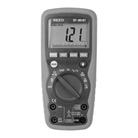
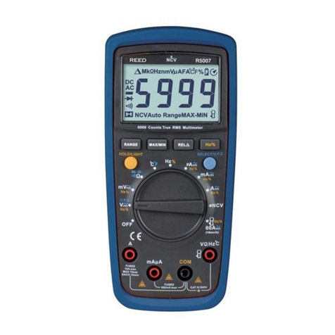
REED ST-9933 User manual

reedinstruments
www com
Model ST-9933
True RMS Autoranging
Digital Multimeter
Instruction
Manual

reedinstruments
www com
2
Table of Contents
Safety ............................................................................................ 3
Features......................................................................................... 4
Specications.............................................................................4-8
Technical..................................................................................4-5
Accuracy .................................................................................5-8
Display Description ....................................................................... 8
Operating Instructions..............................................................9-15
Function Switch .......................................................................... 9
Button Functions .................................................................10-11
Voltage Measurement ............................................................... 11
Current Measurement ............................................................... 11
Resistance (Ω) Measurement .................................................... 12
Continuity Check....................................................................... 12
Diode Test................................................................................. 13
Capacitance Measurement ....................................................... 13
Frequency Measurement .......................................................... 14
Duty Cycle Measurement .......................................................... 14
Temperature Measurement ....................................................... 14
Battery & Fuse Replacement..................................................14-15
For service on this or any other REED product or information on other
REED products, contact REED Instruments at [email protected].

reedinstruments
www com
3
Safety
The following safety information must be observed to insure maximum
personal safety during the operation at this meter:
• Do not use the meter if the meter or test leads look damaged, or if you
suspect that the meter is not operating properly.
•
Never ground yourself when taking electrical measurements. Do not
touch exposed metal pipes, outlets, xtures, etc., which might be at
ground potential. Keep your body isolated from ground by using dry
clothing, rubber shoes, rubber mats, or any approved insulating material.
• Turn the power off to the circuit being tested before cutting, unsolder-
ing, or breaking the circuit. Small amounts of current can be dangerous.
• Use caution when working above 60VCC or 30VAC RMS. Such volt-
ages are a shock hazard.
• When using the probes, keep your ngers behind the nger guards on
the probes.
• Measuring voltage which exceeds the limits of the multimeter may
damage the meter and expose the operator to a shock hazard. Always
respect the meter voltage limits as stated on the front of the meter.
• Replacement fuses must be of the correct type and rating.
• The instrument must not be used if any part of it is damaged.
• Warnings and precautions must be read and understood before an
instrument is used. They must be observed during the operation of this
instrument.
Safety Symbols
CAUTION refer to accompanying notes. This symbol indicates
that the operator must refer to an explanation in the Operating
Instructions to avoid personal injury or damage to the meter.
CAUTION risk of electric shock. This WARNING symbol indi-
cates a potentially hazardous situation, which if not avoided,
could result in death or serious injury.

reedinstruments
www com
4
Features
• True RMS measurements
• Temperature function: 1832°F/1000°C
• AC/DC current to 10A
• Auto and manual ranging
• Data Hold and auto shut off
• Resistance to 40MΩ
• Diode check and continuity functions
• Audible and visual safety warnings
• High contrast 4000-count LCD display with backlight
Specifications
Technical
AC/DC Current Range: 20A
AC Voltage Range: 750V
DC Voltage Range: 1000V
Resistance Range: 40MΩ
Continuity Range: 30Ω
Capacitance Range: 100μF
Frequency Range: 9.999MHz
Temperature Range: Max. 1832°F/1000°C
Safety: Designed to Protection Class III requirement of
EN61010-1 over-voltage Category III (CATIII)
Maximum Voltage: 500V RMS (between any terminal & earth ground)
Display: Oversized high contrast 4000 counts
backlight LCD display with dual display
Polarity: Automatic, (-) negative polarity indication
Overrange: “OL” mark indication
Low battery indication: The “BAT” is displayed when the battery voltage
drops below the operating level
continued ...

reedinstruments
www com
5
Measurement rate: 2 times per second, nominal
Auto power off: Meter automatically shuts down after
approx. 30 minutes of inactivity
Operating environment: 0 to 50°C (32 to 122°F)
at < 70% relative humidity
Storage temperature: -20 to 60°C (-4 to 140°F)
at < 80% relative humidity
Power Supply: Standard 9V battery (NEDA 1604, IEC 6F22)
Dimensions: 197 x 88 x 41mm
Weight: 635g (with holster)
Accuracy
Accuracy is given at 18°C to 28°C (65°F to 83°F), less than 70 % RH
DC Voltage (Auto-ranging)
Range Resolution Accuracy
400.0mV 0.1mV ±0.5% of rdg + 2 digits
4.000V 1mV
±1.2% of rdg + 2 digits40.00V 10mV
400.0V 100mV
1000V 1V ±0.8% of rdg + 2 digits
Input Impedance: 50 MΩ & 400 mV range; 8.2 MΩ & other ranges
Maximum Input: 1000 V DC or 1000 V AC RMS.
AC Voltage (Auto-ranging except 400 mV)
Range Resolution Accuracy
400.0mV 0.1mV ±2.0% of rdg + 3 digits
4.000V 1mV
±0.8% of rdg + 3 digits40.00V 10mV
400.0V 100mV
750V 1V ±2.0% of rdg + 4 digits
Input Impedance: 50 MΩ & 400 mV range; 8.2 MΩ & other ranges
Frequency Range: 40 to 400 Hz
Maximum Input: 1000 V DC or 750 V AC RMS.

reedinstruments
www com
6
DC Current (Auto-ranging for uA and mA)
Range Resolution Accuracy
400.0uA 0.1uA
±1.5% of rdg + 3 digits
4000uA 1uA
40.00mA 10uA
400.0mA 100uA
4.000mA 1mA ±2.5% of rdg + 5 digits
20A 10mA
Overload Protection: 0.5A / 600V and 20A / 600V Fuse.
Maximum Input: 400uA DC or 400 mA AC RMS on uA/mA ranges, 20 A
DC or AC RMS on 20 A range.
AC Current (Auto-ranging for uA and mA)
Range Resolution Accuracy
400.0uA 0.1uA
±1.8% of rdg + 5 digits
4000uA 1uA
40.00mA 10uA
400.0mA 100uA
4.000mA 1mA ±3.0% of rdg + 7 digits
30A 10mA
Overload Protection: 0.5A / 1000V and 20A / 600V Fuse.
Frequency Range: 40 to 400 Hz
Maximum Input: 400uA DC or 400 mA AC RMS on uA/mA ranges, 20 A
DC or AC RMS on 20 A range.
Resistance [Ω] (Auto-ranging)
Range Resolution Accuracy
400.0Ω 0.1Ω ±1.2% of rdg + 4 digits
4.000kΩ 1Ω
±1.0% of rdg + 2 digits
40.00kΩ 10Ω
400.0kΩ 100Ω
4.000MΩ 1kΩ
40.00MΩ 10kΩ ±2.0% of rdg + 3 digits
Input Protection: 500V DC or 500V AC RMS.

reedinstruments
www com
7
Capacitance (Auto-ranging)
Range Resolution Accuracy
40.00nF 10pF ±5.0% of rdg + 7 dgts
400.0nF 0.1nF
±3.5% of rdg + 5 dgts4.000uF 1nF
40.00uF 10nF
100.0uF 0.1uF ±5.0% of rdg + 5 dgts
Input Protection: 500V DC or 500V AC RMS.
Frequency (Auto-ranging)
Range Resolution Accuracy Sensitivity
9.999kHz 0.001Hz ±1.2% of rdg + 5 dgts
0.5V RMS min.
99.99kHz 0.01Hz
999.9kHz 0.1Hz
±1.2% of rdg + 3 dgts
9.999kHz 1Hz
99.99kHz 10Hz 0.8V RMS min.
999.9kHz 100Hz 3.5V RMS min.
9.999kHz 1kHz ±1.5% of rdg + 4 dgts 8.0V RMS min.
Sensitivity: RMS min. at >20% and <80% duty cycle
Sensitivity: More than 100 digits at pulse width >2uSec.
Overload Protection: 500V DC or AC RMS.
Duty Cycle
Range Resolution Accuracy
0.1% to 99.9% 0.1% ±1.2% of rdg ± 2 digits
Frequency: 1 Hz to 150 Hz
Sensitivity: 0.5 V RMS min. when F < 10 kHz; 0.8 V RMS min.
when F > 10 kHz; <100 kHz; 3.5 V RMS min.
when F > 100 kHz; < 150 kHz
Pulse Width: > 100 us, < 100 ms
Overload Protection: 500V DC or AC RMS.

reedinstruments
www com
8
Temperature
Range Resolution Accuracy
-20°C~+1000°C 0.1°C/°C ±3% of rdg ±2 °C/°F
-4°F~+1400°F 0.1°F/°F
Sensor: Type K Thermocouple
Overload protection: 60V DC or AC RMS.
* Room temperature (second display): Resolution: 1°C, Accuracy: ±3°C
Diode Test
Test current Resolution Accuracy
0.3mA typical 1 mV ±10% of rdg + 5 digits
Open circuit voltage: 15V DC typical
Overload protection: 500V DC or AC RMS.
Audible continuity
Audible Threshold: Less than 30Ω
Test current: <0.3mA
Overload Protection: 500V DC or AC RMS.
Display Description (Safety Warnings)
1. First LCD display:
Measured values, unit, symbols,
and decimal points are displayed
2. Second LCD display:
Display Room temperature
3. Test leads are in the
incorrect position
4. F2 fuse is open
5. F1 fuse is open
6. Displays the 2 proper input holes
location at each measuring range.
7. “Disconnect Power” displayed at Ohm, Buzzer, Capacitance,
Diode and Temperature range. Measure from voltage only.
1
2
345
7
6

reedinstruments
www com
9
Operating Instructions
Before taking any measurements, read the Safety information at the
beginning of this manual. Always examine the instrument for damage,
defects excessive dirt, grease, etc. Examine the test leads for cracks or
frayed insulation. If any abnormal conditions exist do not attempt to take
any measurements.
To turn the instrument off, turn the range knob from the OFF position to
any measurement range.
• For the best battery life ALWAYS turn the function switch to the OFF
position when the meter is not in use. This meter has Auto OFF that
automatically shuts the meter OFF after 30 minutes of elapsed time.
•
On some low AC and DC voltage ranges, with the test leads not con-
nected to a device, the display may show a random, changing reading.
This is normal and is caused by the high-input sensitivity. The reading will
stabilize and give a proper measurement when connected to a circuit.
Mode button
Selects the unit of measurement. The following is a list of the function
selections. Simply turn the the function switch to the appropriate symbol
for the measurement you require.
Position(s) Measurement(s)
OFF Turns the meter off
V AC/DC Voltage
Ohm/Diode/Continuity
CAP Capacitance
Hz % Duty cycle
°C/°F Temperature °C/°F
10A/mA/μA AC/DC Current

reedinstruments
www com
10
RANGE button
When the meter is rst turned on, it automatically goes into AutoRanging.
This automatically selects the best range for the measurements being
made and is generally the best mode for most measurements.
For measurement situations requiring that a range be manually selected,
perform the following:
1. Press the RANGE button. The “Auto Range” display indicator will turn
off, The “Manual Range” display indicator will turn on
2. Press the RANGE button to step through the available ranges until you
select the range you want.
3. Press and hold the RANGE button for 2 seconds to exit the Manual
Ranging mode and return to AutoRanging.
Data Hold button
The HOLD function allows the meter to “freeze” a measurement for later
reference.
1. Press the HOLD button to “freeze” the reading on the indicator. The
“HOLD” message will be appear in the display.
2. Press the HOLD button again to return to normal operation.
The data hold function will be canceled automatically when the function
switch is changed.
Relative Zero button
For convenient readings comparison & offset.

reedinstruments
www com
11
Input Jacks
This meter has four input jacks that are protected against overload to the
limits of 20A. During use, connect the Black test lead to the COM jack and
the Red test lead as shown below:
Function Red lead Connection Input limits
DCV/ACV “+” 1000V DC or 750 AC RMS
Ω “+” 500V DC or AC RMS
CONTINUITY/DIODE “+” 500V DC or AC RMS
CAP “+” 500V DC or AC RMS
Hz/% “+” 500V DC or AC RMS
uA/mA “+” 400mA DC or AC RMS
A 10A 10A DC or AC RMS
TEMP. Temp. jack 60V DC or 24 AC RMS
Voltage Measurement
1. Insert the black test lead into the negative COM terminal and the red
test lead into the positive V terminal.
2. Set the function switch to the DCV or ACV position.
3. Connect the test leads to the source or load being measured.
4. Read the voltage measurement on the LCD display. The polarity of the
Red connection will be indicated when making a DC measurement.
Current Measurement
1. Insert the black test lead into the negative (COM) terminal and the red
test lead into the positive (μA, mA) terminal for a maximum measure-
ment of 400mA. For a maximum measurement of 10A, move the red
test lead to the positive (A) terminal.
2. Set the function switch to the μA, mA or A position and press the DC/AC
button to select the DCA or ACA measurement mode.
3. Connect the test leads to the source or load being measured.
4. Read the voltage measurement on the LCD display. The polarity of the
Red connection will be indicated when making a DC measurement.

reedinstruments
www com
12
Resistance Ω Measurement
WARNING:
To avoid electric shock, disconnect power to the unit under test
and discharge all capacitors before taking any resistance mea-
surements. Remove the batteries and unplug the line cords.
1. Insert the black test lead into the negative COM terminal and the red
test lead into the positive Ωterminal.
2. Set the function switch to Ω.
3. Make sure the power of the circuit being measured is off.
4. Connect the test leads to the circuit being measured. The range will
change automatically, and will be held on the range that will display the
measured resistance with the best resolution.
5. The value indicated on the display is the measured value of resistance
to the correct decimal point and annunciation indication.
Continuity Check
WARNING: To avoid electric shock, never measure continuity on circuits
or wires that have voltage on them.
1. Insert the black test lead into the negative COM terminal and the red
test lead into the positive Ω terminal.
2. Set the function switch to the diode/continuity position.
3. To select continuity test measurement mode, press the MODE button
until the (diode/buzzer) symbol appears in the display on the left
hand side. In the continuity mode, a buzzer will sound when the resis-
tance of the circuit to be measured is less than approximately 30Ω.

reedinstruments
www com
13
Diode Test
WARNING: To avoid electric shock, do not test any diode that has
voltage on it.
1. Insert the black test lead into the negative COM terminal and the red
test lead into the positive Diode terminal.
2. Set the function switch to the diode/continuity position.
3. Make sure all the power is off.
4. To select the diode test measurement mode, press the MODE button
until the (diode/buzzer) symbol appears in the display on the left
hand side. Pressing the MODE button again will switch the measure-
ment mode to continuity test.
5.
Connect the test leads to the diode being measured. When measuring the
forward voltage across diode, a normal diode will indicate 0.4V to 0.7V
and the reverse voltage will indicate “OL” (same as on open condition).
For a short-circuited diode, a value near 0 mV will be displayed.
Capacitance Measurement
WARNING: To avoid electric shock, discharge the capacitor under
test before measuring.
1. Insert the black test lead into the negative COM terminal and the red
test lead into the positive CAP terminal. The polarity of the lead con-
nection is positive “+”.
2. Set the function switch to the CAP position.
3. Connect the test leads across the capacitor being measured and be
sure that the polarity of the connection is respected.
Notes:
• When checking in-circuit capacitance, be sure that the circuit’s power
has beened turned off and that all capacitors are fully discharged.
•
In capacitance measurement mode the range control mode is auto-ranging.

reedinstruments
www com
14
Frequency Measurement
1. Insert the black test lead into the negative COM terminal and the red
test lead into the positive Hz terminal.
2. Set the function switch to the Hz % position.
3. To select the frequency measurement mode, press the MODE button
until the (frequency) Hz symbol appears in the display on the left hand
side. Pressing the MODE button again will switch the measurement
mode to duty cycle check.
4. Connect the test leads to the circuit being measured. The range will
change automatically, and will be held on the range that will display the
measured frequency with the best resolution.
Duty Cycle Measurement
1. Insert the black test lead into the negative COM terminal and the red
test lead into the positive Hz terminal.
2. Set the function switch to the Hz % position.
3.
To select the duty cycle measurement mode, press the MODE button until
the (duty cycle) % symbol appears in the display on the left hand side.
4. Connect the test leads to the circuit being measured. The range will
change automatically, and will be held on the range that will display the
measured duty cycle with the best resolution.
Temperature Measurement
1. Set the function switch to the °C/°F position.
2. Connect the positive sensor to the μA/mA terminal and the negative
sensor to the COM terminal.
3. Connect the K-Type test line to the sensor (positive to positive and
negative to negative).
4. Connect the test line to the test point beign measured.
5. Read the temperature measurement on the LCD display.
continued ...

reedinstruments
www com
15
Battery & Fuse Replacement
WARNING: To avoid electric shock, disconnect the test leads from any
source of voltage before removing the battery or fuse cover.
Do not operate your meter with the cover removed. Be sure
it is in place and fastened securely.
Battery Replacement
When the battery level gets low or falls below the operating voltage, the
battery warning symbol will appear in the LCD display.
1. Disconnect the test leads from the meter.
2. Open the battery cover by loosening the screws using a Phillips head
screwdriver.
3. Insert the battery into battery holder, observing the correct polarity.
4. Put the battery cover back in place. Secure with the two screws.
NOTE: If your meter does not work properly, check the fuses and battery
to make sure that they are still good and that they are properly
inserted.
Replacing The Fuses
1. Disconnect the test leads from the meter and any item under test.
2. Open the fuse door by loosening the screw on the door using a Phillips
head screwdriver.
3. Remove the old fuse from its holder by gently pulling it out.
4. Install the new fuse into the holder.
5. Always use a fuse of the proper size and value
(F1 500mA / 600V fast blow, F2 10A / 600V fast blow).
6. Put the fuse door back in place. Insert the screw and tighten it securely.
For service (repairs or calibration) on this or any other REED product
or information on other REED products, contact REED Instruments
at info@reedinstruments.com.

reedinstruments
www com
16
Notes _________________________________________
________________________________________________
________________________________________________
________________________________________________
________________________________________________
________________________________________________
________________________________________________
________________________________________________
________________________________________________
________________________________________________
________________________________________________
________________________________________________
________________________________________________
________________________________________________
________________________________________________
________________________________________________
________________________________________________
________________________________________________

reedinstruments
www com
ST-9933
Manuel
d’utilisation
Multimètre numérique TRMS
à sélection automatique
de la gamme
Modèle

reedinstruments
www com
2
Table des matières
Sécurité ......................................................................................... 3
Caractéristiques ............................................................................ 4
Spécications.............................................................................4-8
Techniques ..............................................................................4-5
De précision.............................................................................5-8
Description de l’afchage.............................................................. 8
Mode d’emploi .........................................................................9-15
Sélecteur de fonction .................................................................. 9
Boutons de fonction.............................................................10-11
Mesure de la tension................................................................. 11
Mesure du courant.................................................................... 11
Mesure de la résistance (Ω)....................................................... 12
Test de continuité...................................................................... 12
Test de diode ............................................................................ 13
Mesure de la capacité............................................................... 13
Mesure de la fréquence ............................................................ 14
Mesure du cycle de service....................................................... 14
Mesure de la température ......................................................... 14
Remplacement de la pile et du fusible...................................14-15
Pour faire réparer cet instrument ou tout autre produit de REED ou pour
obtenir de plus amples renseignements sur les autres produits de REED,
communiquez avec REED Instruments à info@reedinstruments.com.

reedinstruments
www com
3
Sécurité
Il faut respecter les directives de sécurité suivantes pour assurer la
sécurité optimale de l’utilisateur de l’instrument:
•
N’utilisez pas l’instrument si celui-ci ou les ls de lecture semblent endomma-
gés ou si vous soupçonnez que l’instrument ne fonctionne pas correctement.
•
Ne vous mettez jamais à la terre pour mesurer un courant électrique. Ne
touchez pas à des tuyaux, à des prises, à des appareils d’éclairage ou à tout
autre dispositif exposé qui pourrait vous mettre à la terre. Demeurez isolé en
portant des vêtements secs et des chaussures en caoutchouc, en utilisant
un tapis de caoutchouc ou tout autre matériau isolant homologué.
• Avant de couper, dessouder ou briser un circuit, coupez-en l’alimentation.
Même en petite quantité, le courant peut être dangereux.
•
Faites preuve de prudence lorsque vous mesurez un courant supérieur à
60 Vc.c. ou à 30 Vc.a. RMS. Une telle tension constitue un danger de choc.
• Lorsque vous utilisez des sondes, gardez les doigts derrière le dispositif de
protection.
• La mesure d’un courant dépassant les limites du multimètre peut endom-
mager l’instrument et exposer l’utilisateur à un risque de choc électrique.
Respectez toujours la limite de tension indiquée sur l’avant de l’instrument.
• Les fusibles de remplacement doivent être du même type et du même
calibre que le fusible d’origine.
•
Il ne faut pas utiliser l’instrument s’il présente quelque dommage que ce soit.
• Lisez et comprenez tous les avertissements et toutes les précautions avant
d’utiliser l’instrument. Il faut les respecter en tout temps durant l’utilisation
de l’instrument.
Symboles de sécurité
ATTENTION Voir le mode d’emploi. Ce symbole indique
à l’utilisateur de consulter une explication dans le mode
d’emploi pour éviter de se blesser ou d’endommager l’appareil.
ATTENTION risque de choc électrique. Ce symbole
AVERTISSEMENT indique une situation potentiellement
dangereuse qui, si elle n’est pas évitée, pourrait causer
des blessures sérieuses ou la mort.

reedinstruments
www com
4
Caractéristiques
• Mesures TRMS
• Fonctions de mesure de la température: 1832 °F/1000 °C
• Mesure du courant c.a./c.c. jusqu’à 10 A
• Sélection automatique et manuelle de la gamme
• Stockage des lectures et arrêt automatique
• Mesure de la résistance jusqu’à 40 MΩ
• Fonctions de test de diode et de test de continuité
• Signaux d’avertissement sonores et visuels
• Écran ACL rétroéclairé et à haut taux de contraste afchant
les chiffres jusqu’à 4000
Spécifications
Techniques
Gamme de courant c.a./c.c.: 20 A
Gamme de tension c.a.: 750 V
Gamme de tension c.c.: 1000 V
Gamme de résistance: 40 MΩ
Gamme de continuité: 30 Ω
Gamme de capacité : 100 μF
Gamme de fréquence: 9.999 MHz
Gamme de température: Temp. 1832 °F/1000 °C
Sécurité: Conçu pour respecter la classe de protection III
de la norme EN61010-1 – protection contre les
surtensions de catégorie III (CATIII)
Tension maximum: 500 V RMS (entre n’importe quelle borne
et la mise à la terre)
Afchage: Écran ACL surdimensionné à haut taux
de contraste et rétroéclairé à afchage double.
Afche les chiffres jusqu’à 4000.
Polarité: Indication automatique de la polarité négative (-)
Dépassement de la gamme:
La mention “OL” indique le dépassement.
Indication de pile faible: La mention “BAT” est afchée lorsque la tension
de la pile tombe sous la limite fonctionnelle.
suite...
Table of contents
Languages:
Other REED Multimeter manuals