SHOTO SDA-10 User manual

48V100Ah Lithium-ion Battery module for
telecommunication
User Manual
(V1.0)

1
Contents
1. Brief introduction ............................................................................. 3
2. Product features................................................................................ 3
3. Product advantages........................................................................... 4
4. Product types andtechnical parameters ........................................... 5
5. Environmental requirements ............................................................ 6
6. Systempanel functions..................................................................... 6
6.1 Systempanel Schematic drawing...................................... 6
6.2 Battery output terminal ...................................................... 7
6.3 Reset key............................................................................ 7
6.4 Communication interface................................................... 8
6.4.1 Cascade communication interface......................... 8
6.4.2 Upper connection communication interface ......... 9
6.4.3 Communication wire............................................. 9
6.5 Dial switch ....................................................................... 10
6.6 LED signal introduction................................................... 10
6.7 Dry contact....................................................................... 12
6.8 Groundingterminal.......................................................... 13
6.9 Air switch......................................................................... 14
6.10 Gyro anti-theft function(optional).................................. 14
7.System workingprinciple and parameters ...................................... 15
7.1 System workingprinciple ................................................ 15
7.2 Charge parameters............................................................ 15
7.3 Discharge parameters...................................................... 16
7.4 System protection function and parameters................... 16
8. System installation, uses and maintenance..................................... 18
8.1 System installation........................................................... 18

2
8.1.1 19 "standard rack embedded installation ............. 18
8.1.2 Scaffolding installation ........................................ 20
8.1.3 Installation of equipment cabinet type................. 23
8.1.4 Installation of wall mountingtype................ 24
8.2 System power on.............................................................. 27
8.2.1 SystemActivation................................................ 27
8.2.2 System Standby................................................... 27
8.3 Warningexplanation and processing ............................... 28
8.4 Communication breakdown ............................................. 30
8.5 Protection breakdown ...................................................... 30
8.5.1 Over charge protection......................................... 30
8.5.2 Current protection................................................ 31
8.5.3 Other breakdown ................................................. 31
8.6 Particular circumstance processing.................................. 31
8.6.1 Power outage ....................................................... 31
8.6.2 Cataclysm accident .............................................. 31
8.7 Normal operation and maintenance of LFP battery......... 31
8.8 Stable and reliable switch power supply.......................... 32
9. Packaging transportion and storage................................................ 32
9.1 Packaging......................................................................... 32
9.2 Transportation.................................................................. 32
9.3 Storage ............................................................................. 33
10. Environment protection request................................................... 33
11. Safety iessues needing attention................................................... 33

3
1. Briefintroduction
Communication LFP battery module is a high-tech product.The
product has many merits, mainly including: integration,
miniaturization, light-weight, intelligent centralism monitoring, the
battery maintenance and management, unattended, standardization
installation and easy operation, at the same time, environment friendly.
Now the product has been widely used as backup power in
telecommunication field such as access network equipment, far-end
telephone exchange, mobile telecommunication equipment,
transmission facility, satellite earth station and microwave
communication equipment, etc. At present, LFP backup battery
telecommunication series products have been put into mass production
and are widely used at home and abroad.
2. Product features
(1) The battery positive electrode is made of LFP, which has long
cycling life and good safety.
(2) The battery module adopts the high-performance BMS, which
has the protectivefunctions of current, voltage and temperatureetc..
(3) The monitoring unit automatically measures charging and
discharging current, voltage, surface temperature of the cells and
ambient temperature.
(4) The system can seamlessly turn on after the public electricity
fails. When the discharge voltage is below the warning parameter
set-up in advance, the battery will automatically send the warning

4
signal. When discharge voltage is below the protect parameter, the
battery will automatically turn off.
(5) The battery module has fine electromagnetic compatibility.
(6) Fully intelligent design, equipped with centralized monitoring
module and telemeters, telesignalisation, remote regulating, remote
control function, realizes intelligent management, and can correspond
withthe far-end central monitoring center.
(7) The organic combination of the power source control technology
and the computer can monitor and control various parameters and
statein real time.
(8) Adoptingthe self-coolingmethod, the system has extremely low
noise.
3. Product advantages
(1) Realize the work directly under the primary DC
telecommunication switching power supply system with the constant
charge and discharge working mode.
(2) LFP backup battery module is the high-tech product
manufactured by Group, with proprietary intellectual property rights,
the product fills in the domestic blank,and the key technical indexes is
in the lead level of the world.
(3) LFP backup battery module is the first bulk production in
domestic, and is widely used in the telecommunication filed, with the
longest market time, biggest market quantity and good market
reaction.

5
(4) In order to satisfy Telecom Operator’s new demands on the
power-supply system, developed the integrative backup battery
module solution based on LFP battery, BMS, DC switch power
module or ups (uninterrupted powersystem).
(5) Higher gravimetric specific energy, during installing, there is no
extra demand for space and bearing compared with VRLA battery,
greatly reducing the cost of the area rented.
(6) Good temperature characteristics : working environment
temperature can reach -20~+60℃(recommended temperature:+15~
+35℃), which greatly reduces powerconsumptioncost.
(7) LFP battery has excellent rate discharge performance, which
enables LFP battery with small capacity to meet large current
discharge requirements.
(8) Flexible allocation: muti-LFP battery modules in parallel, make
large capacity LFP battery module become true, not only enhance the
output power of the system, but also prolong the backup time of the
battery module.
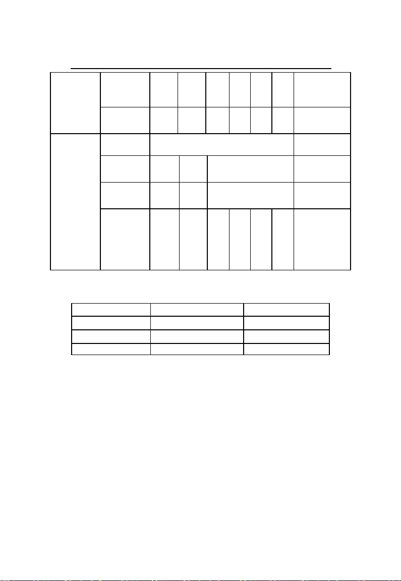
4. Product types and technical parameters
Table 4-1 48V series of product specifications and models
Model
Nominal
voltage
(DC V)
Nominal
capacity
(Ah)
Maximum
load
current(A)
Dimension (mm)
(width×depth×height)
Weight
(kg)
Remarks
48V100Ah
48
100
50
442×400×176(4U)
45
parallel system
48V100Ah
48
100
50
442×480×176(4U)
45
parallel system
48V150Ah
48
150
100
442×480×266 (6U)
65
parallel system
48V200Ah
48
200
100
442×480×354 (8U)
86
parallel system

6
Note: sizedeviation is ±2mm,Weight deviation is ±2Kg.
Remarks :The size of thetable above is only for the battery module,
excluding cabinet, rack, rain box, etc. In order to ensure the safety,
reliability and stability of high-capacity LFP battery parallel system,
the expected capacity must be consistent withthe actual capacity.
5. Environmental requirements
Ambient temperature:-20~+60℃(suggested temperature:
+15~+35℃);
Storage temperature:-40~+70℃(suggested temperature:
+15~+35℃);
Relative humidity:5%~85%RH;
Hight:not exceeding 4000m;
No conductive dust and corrosive gas place.
6. Systempanel functions
6.1 Systempanel Schematicdrawing

7
Pic. 6-1 Schematic drawing of the module panel
6.2 Battery output terminal
The number of “1” in Pic. 6-1 show the output terminal of the
battery module. It adopts one4 pin terminal.
Table 6-1 different output configurations of the battery modules
Battery model
Battery
capacity
Screw
specification
Wiring
request
Line nose
48V100Ah
100Ah
--
≥10mm²
OT10-6/SC16-8
More than 100Ah
--
--
≥10mm²
OT10-6/SC16-8
6.3 Resetkey
The number of “2” in Pic. 6-1 represents “RESET” key. When
the system runs into abnormal status, one can use the key to reset the
system to ensure the stability of the system. At the same time, in order
to facilitate the use in different application scenarios, booting,
shutdown and reset functions are integrated into this key. Specific
definitions are shownin theTabke 6-2 below.
Table 6-2 booting/shutdown, reset keys’ definitions

8
No.
Functions
Definitions
Remarks
1
booting/
activation
When battery is dormant, press this key and hold
for 3s, then the battery is activated and theLED
indicator lights up in turn. Thebattery is turned
into the normal working status.
2
shutdown/
dormancy
When battery is in standby or working status,
press this key and hold for 3s, the LED indicator
lights up in turn. Thebattery is turned into the
dormant status.
3
Reset
When the battery is in standby or working
condition, the battery is reset and the internal data
will be restored to the factory status after pressing
this key and holding for 6s.
6.4 Communication interface
6.4.1 Cascade communication interface
The number of “3” in Pic. 6-1 represents RS485 communication
ports which communicate with upper computer and the other modules
in the cascade connection among the modules. The ports adopt two
8P8C straight PCB welding telephone sockets (round pin). The
module panel is configured with two RS485 ports, which are serial
ports physically. When the battery modules are cascaded, the
communication address 000001 is defined as the master module, and
the others are defined as the slave module. The slave module can
communicate with the master module through the RS485. The master
module manages the data of each battery in the cascade system.
RS485 definition is shown in Table 6-3.
Table 6-3 The pins definition of the RS485 port
Pin
Definitions
1
RS485-B

9
2,7
RS485-A
3
NC
4
NC
5
NC
6
NC
8
GND
6.4.2 Upper connection communication interface
The number of “4” in Pic. 6-1 represents RS232 communication
port, its default baud rate is 9600bps. RS232 port adopts 6P4C straight
PCB welding telephone socket (round pin). Through the RS232 port,
the master battery module can communicate with the upper computer.
When the modules are cascaded, only the master module can
communicate with the upper computer and upload data, status and
information of all of the battery module in the cascade system, which
achieves central monitoring and management, and realizes several
remote functions. RS232 communication interface definition is shown
in Table 6-4.
Table 6-4 The pins definition of the RS232 port
Pin
Definitions
1,2,6
NC
3
TX
4
RX
5
GND
6.4.3 Communication wire

10
Pic. 6-2 shows the cascade communication wire connections of
RS485.
Pic. 6-2 The cascade communication wire connections of RS485
6.5 Dial switch
The number of “5” in Pic. 6-1 represents the six-bit of dial switch,
it can define the address of the module in cascade from 0 to 15. The
default address of dial code switch is 000000 (that is, the address is
"0"). If the number of battery modules in the cascade system is greater
than 15, the address code of the battery module should be set through
the softwareof the uppercomputer.
6.6 LED signal introduction
(1)Capacity signal light(SOC,green)
capacity signal light: 4 green lights, each light indicates 25%
capacity. When capacity is 100%, 4 lights are all on; when capacity is
75% ,the first light on the left extinguishs, and the other 3 lights are on;
when capacity is 50%, 2 lights on the left extinguish, and 2 lights on
the right are on; when capacity is 25%, 3 lights on the left extinguish,
and the first light on the right is on.
(2)Systemrunningindicatorlight(RUN,green)

11
RUN light, green, is always on duringcharging, and is on and off
for 0.5 second separately duringdischarging.
(3)Alarm indicator light(ALM, red)
ALM light, red, it’s on when the system breaks down. The
definition of specific indicator light is shownin Table 6-5:
Table 6-5 LED signal difinitions
System
status
Operation
status
RUN
ALM
LED
Remark
●
●
●
●
●
●
Shut down
Dormancy
off
off
off
off
off
off
All are off
Standby
Normal
flash
1
time
off
off
off
off
off
Standby
Alarm
flash
3
times
flash
3
times
off
off
off
off
Alarm and
Run flash 3
times
Charge
Normal
on
off
Indicating according to
actual capacity
According to
capacity, flash
2 times
Over
voltage
protect
on
off
on
on
on
on
RUN light:
Bri when the
power online,
be standby
when the
power is
offline
Over
current
protect
off
on
off
off
off
off
Stop charging
and
discharging
and force to
sleep after no
operation for
24 hours
Discharge
Normal
flash
3
times
off
Indicating according to
actual capacity
According to
capacity, it’s
on all the time
Alarm
flash
3
times
flash
3
times
Over
current,
short
off
on
off
off
off
off
Stop charging
and
discharging
12
circuit,
reverse
connection
protection
and force to
sleep after no
operation for
24 hours
Low
voltage
protection
off
off
off
off
off
off
Stop
discharging
Temperatur
e
normal
According to normal state to signal
---
Alarm
during
charging
on
flash
3
times
Indicating according to
actual capacity
According to
capacity to
flash 2 times
Alarm
during
discharging
Flash
3
times
flash
3
times
Indicating according to
actual capacity
According to
capacity, it’s
on all the time
Protection
off
on
off
off
off
off
Stop charging
and
discharging
and force to
sleep after no
operation for
24 hours
Table 6-6 LED flash mode definitions
Flash mode
on
off
flash 1 time
0.25s
3.75s
flash 2 times
0.5s
0.5s
flash 3 times
0.5s
1.5s
6.7 Dry contact
The number of “9” in Pic. 6-1 represents the dry contact, which is
an interface through which the battery module sends the alarm or
protection signals. When the BMS has a protection or warning signal,
the dry contact sends a switch signal through the corresponding
interface.

13
Table 6-7 Dry contact definitions
Note: Dry contact is off when BMS is in dormancy.
6.8 Grounding terminal
The number of “10” in Pic. 6-1 represents the grounding
terminal, which is used to connect to the ground. With the ground
terminal, the module can protect itself when an abnormal fault occurs
from itself and theother equipments.
DRY
Definition
Status
Normal
Alarm
DRY1
Soc 20%-when SOC is lower than
20%,dry contact alarm
NC
NO
DRY2
Security feature enabled-Anti-theft
function on Dry contact in alarm
NC
NO
DRY3
Under voltage alarm and protection
NC
NO
DRY4
Charge discharge current alarm and
protection、Short circuit
protection、Reverseconnection
protection
NC
NO
DRY5
High and low temperature alarm
and protectionof charge and
discharge
NC
NO
DRY6
Alarm occurs(No action in case of
charging current limit)
NC
NO
DRY7
Protection and failure(No action in
case of charging current limit)
NC
NO

14
6.9Air switch
The number of “11” in Pic. 6-1 represents the air switch, which
is used to disconnect the battery module and the other equipment
when the battery module is short-circuited or in over-current
condition.
6.10 Gyro anti-theftfunction(optional)
The BMS has a gyro anti-theft function, which can be
controlled by the host computer software to. By default, the gyro
anti-theft is activated by charging method.
The BMS PC software can set the gyro anti-theft function
activation mode. When use charging activation to activate the gyro
anti-theft function, the BMS detects that the charging current is
greater than 5A, and the time more than 30s, BMS automatically
activates the gyro anti-theft function.
After the gyroscope is fixed, the initial position state of the
gyroscope can be set by the PC software. When the gyroscope module
has an angular offset of more than 30°in any direction, After a period
of time delay (default 3s), BMS turn off the discharge MOSFET, and
lock the battery. The battery can be charged normally but cannot
discharge any more.
The locked battery can be unlocked by the host computer
software. If the gyroscope returns to the initial position after
unlocking, the battery can be charged and discharged normally. If the
gyroscope module is still offset from the initial position by 30°, the
BMSwill still delay for a period of time (default 3s). and then turn off
the discharge MOSFET, cut off the output and lock the battery. The
battery can be charged normally but cannot discharge.
15
6.11 GPS module installation window
The number of “12”in Pic. 6-1 represents theGPS reserved
window,When it is necessary toinstall the GPS module, remove the
screws at four corners and fix the GPS module witha cable tie。
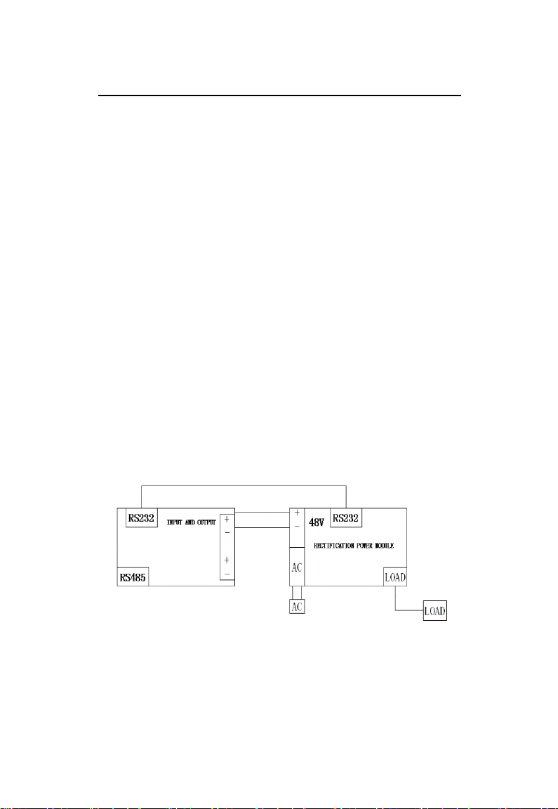
7.Systemworking principle and parameters
7.1 Systemworking principle
48V100Ah LFP back up battery module working principle is
shown in Pic. 7-1. The rectifier inputs AC220V power source, and
output DC -48V. Under normal grid conditions, the rectifier supplies
the working current for the load and at the same time charges the
battery module. When grid is off, the battery module supplies direct
current for the load, which achieves uninterrupted power supply.
When the battery module voltage is extremely low, the BMS will
automatically cut off powersupply to extendthe battery life.
Pic. 7-1Working principle diagram of LFPbattery module
7.2 Charge parameters
Table 7-1 Charge parameters
48V100Ah

16
Model
Charge voltage(DC V)
Charge current(A)
Mini
mum
Typical
value
Maxi
mum
48V100Ah(15S)
53.2
56.4
57.5
Charge current,
≤1C3
48V100Ah(16S)
56.4
57.6
60.4
7.3 Discharge parameters
Table 7-2 Charge parameters
Model
Discharge voltage(DCV)
Discharge current
(A)
Mini
mum
Typical
value
Maxi
mum
Typical
value
Maximum
48V100Ah(15S)
40
48.0
53.0
0.2C3
1C3
48V100Ah(16S)
41.6
51.0
55.0
0.2C3
1C3
7.4 Systemprotection function and parameters
Table 7-3 Protection functions and parameters
Number
Protection project
Default value
15 string
system
16 string
system
1
systemtotal
voltage high
protection
and recover
Alarm value
54.00V
57.00V
Alarm recovery value
52.50V
56.00V
Protection value
54.75V
57.75V
Protection Recovery
value
50.1V
53.5V
Discharge current,total
voltage<50.1V
2
Systemtotal
voltage low
protection
and recover
Alarm value
42V
42V
Alarm recovery value
43.2V
43.2V
Protection value
40V
40V
Protection Recovery
value
Charge current recovery,
total voltage>43.2V
3
Short-circuit
protection
Protection value
Protection and alarn
4
Cell voltage
Alarm value
2.5V

17
low
protection
and recover
Alarm recovery value
2.7V
Protection value
2.5V
Protection Recovery
value
Charge current recovery,
cell voltage>2.7V
5
Cell voltage
high
protection
and recover
Alarm value
3.7V
Alarm recovery value
3.34V
Protection value
3.65V
Protection Recovery
value
Discharge current
recovery,cell voltage<
3.34V
6
Charge over
current
protection
(no charge
limited
current)
Alarm value
1.05C3A
Alarm recovery value
1.0C3A
Protection value
1.1C3A
Protection Recovery
value
Discharge or manual reset
7
Discharge
over current
protection
Alarm value
1.05C3A
Alarm recovery value
1.0C3A
Protection value
1.1C3A
Protection Recovery
value
Charge or manual reset
8
Cell high
temperature
protection
and recover
Charge high
temperature protection
value
60℃
Charge high
temperature recovery
value
50℃
Discharge high
temperature protection
value
60℃
Discharge high
temperature recovery
value
50℃
9
Cell low
temperature
protection
and recover
Charge low temperature
protection value
0℃
Charge low temperature
recovery value
5℃
Discharge low
temperature protection
value
-20℃

18
Discharge low
temperature recovery
value
-10℃
10
The
environment
temperature
protection
and recovery
High temperature alarm
value
65℃
Low temperature alarm
value
-20℃
High temperature
protection value
70℃
High temperature
recovery value
65℃
Low temperature
protection value
-25℃
Low temperature
recovery value
-20℃
Note : The table above is the default parameters, specific setting
parameters may be changed, please refer to our actual product
parameters.
8. Systeminstallation,usesandmaintenance
8.1 Systeminstallation
8.1.1 19 "standard rack embedded installation
Pic. 8-1 48100 installation drawing
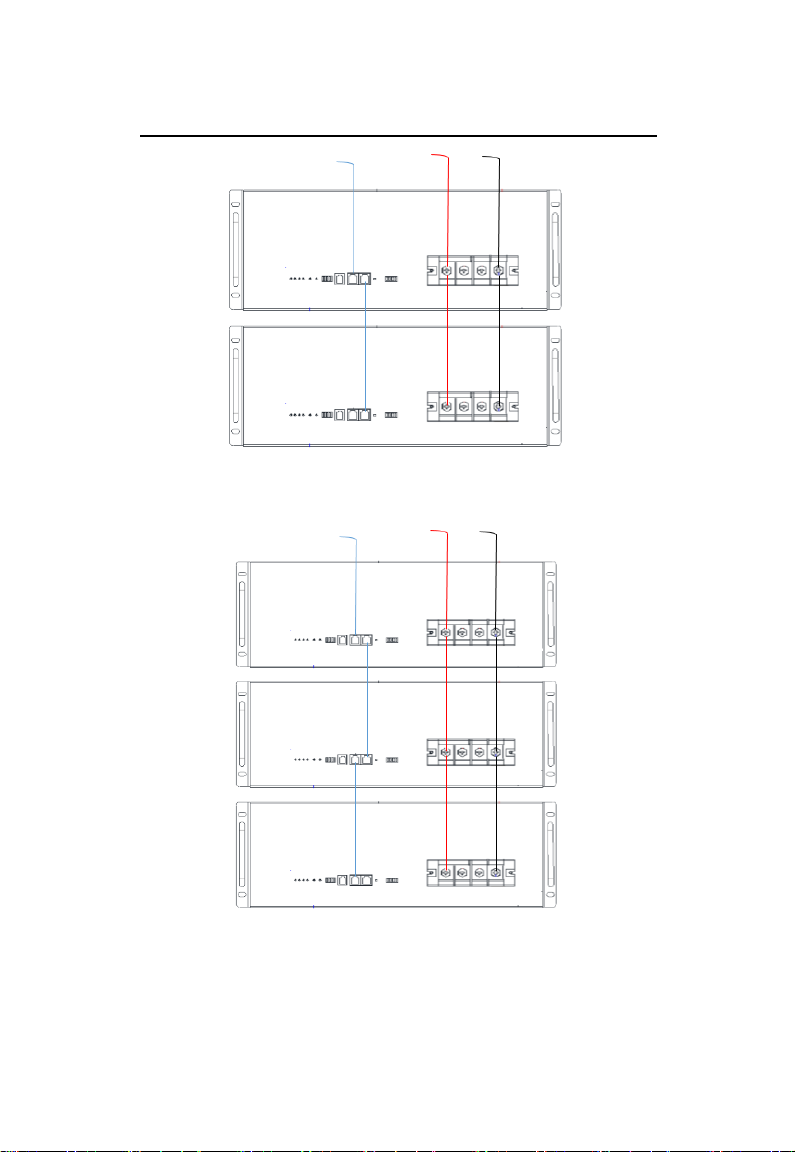
19
Pic. 8-2 48200 installation drawing
Pic. 8-3 48300 installation drawing
Other manuals for SDA-10
1
Table of contents
Popular Control Unit manuals by other brands

Linear
Linear LTC2803 quick start guide

NuWave
NuWave NWVS-4 Installation and user manual

Fastrax
Fastrax SD5LCDN instruction manual

Armstrong
Armstrong GP-1 Installation & maintenance instructions

Jordan Valve
Jordan Valve I & M Mark EW Series Installation & maintenance instructions

Integra
Integra 201-33 instruction sheet

flamco
flamco Flamcovent Smart manual

Vapac
Vapac VapaNet LFE Series Installation & operation manual

Telebyte
Telebyte GHN-AT-PROG-UPLC-3-SLOPE reference guide

Calmotion
Calmotion USBCNC Machine Mount instructions

Grundfos
Grundfos DDI Series Supplement to installation and operating instructions

elobau
elobau 471 M41 H31 Translation of the original operating instructions


