Show Pro Industries PRO CUTTER 1502 User manual

PRO CUTTER 1502
with “EYE-BALL” Training Package
Show Pro Industries would like to thank you for purchasing a Pro
Cutter. Every effort has been taken to provide you with a quality product
that is designed to provide years of trouble-free service.
SHOW PRO INDUSTRIES
P.O. Box 1235 (Hwy. 51 N.), Springtown, TX 76082 / (817)523-4055 / (817)220-5117 fax
*Shown here with optional mounting bracket

Packing List:
control box (steel box containing electronic equipment
antenna
remote control (worn on rider’s wrist)
inflatable bladder with hand pump
black and white ball cover
slide tubes
kevlar cable
cable tensioner
installation instructions

INSTALLATION INSTRUCTIONS
1. Mount control box: Securely attach control box on one side of
arena. It should be mounted so pulleys on bottom of box are
approximately 45 inches from ground.
2. Mount cable tensioner: Mount cable tensioner on opposite side of
arena approximately 45 inches from ground. An included bracket
allows mounting to either a flat panel or post.
3. Prepare Eye Ball for Installation: Insert inflatable bladder into
nylon cover. Use hand pump to inflate the bladder to approx 20” in
size. DO NOT over-inflate bladder. When properly inflated, the
“Eye Ball” should be firm with a slight “squish” to allow for
expansion/contraction caused by temperature changes.
4. Install “Eye Ball”& Kevlar cable:
To install kevlar cable, start in center of arena.
a. The “Eye-Ball” comes with two slide tubes; one which has kevlar
cable pre-installed and one without cable.
b. Take end of cable
b. Start in the center of the arena. Take one end of cable around
pulley on bottom of control box. Install the “free-sliding” slide
tube onto the cable and run it around cable tensioner pulley, then
back to center. Tie each end onto the front slide tube. Tighten.
Cut off excess cable.
c. Use the velcro straps to attach the “Eye Ball”to the slide tubes.
Ties to front line
Slides freely on back line
5. Install antenna:Remove shipping cap from antenna connecter on
top of control box. Insert whip antenna into connecter, push down,
and twist clockwise approximately ¼ turn. You should feel antenna
lock into position. (To remove antenna, squeeze base and twist
counter-clockwise)
*Do not discard the protective cap. Re-use cap to protect antenna connector
when antenna is not installed.
6. Apply power: Plug Pro Cutter into grounded 120VAC, 3-prong
outlet. Waiting a few minutes before operating allows the climate
control system to stabilize temperatures and remove condensation.
Always unplug unit when not in use. *EURO MODELS: 240VAC/50Hz
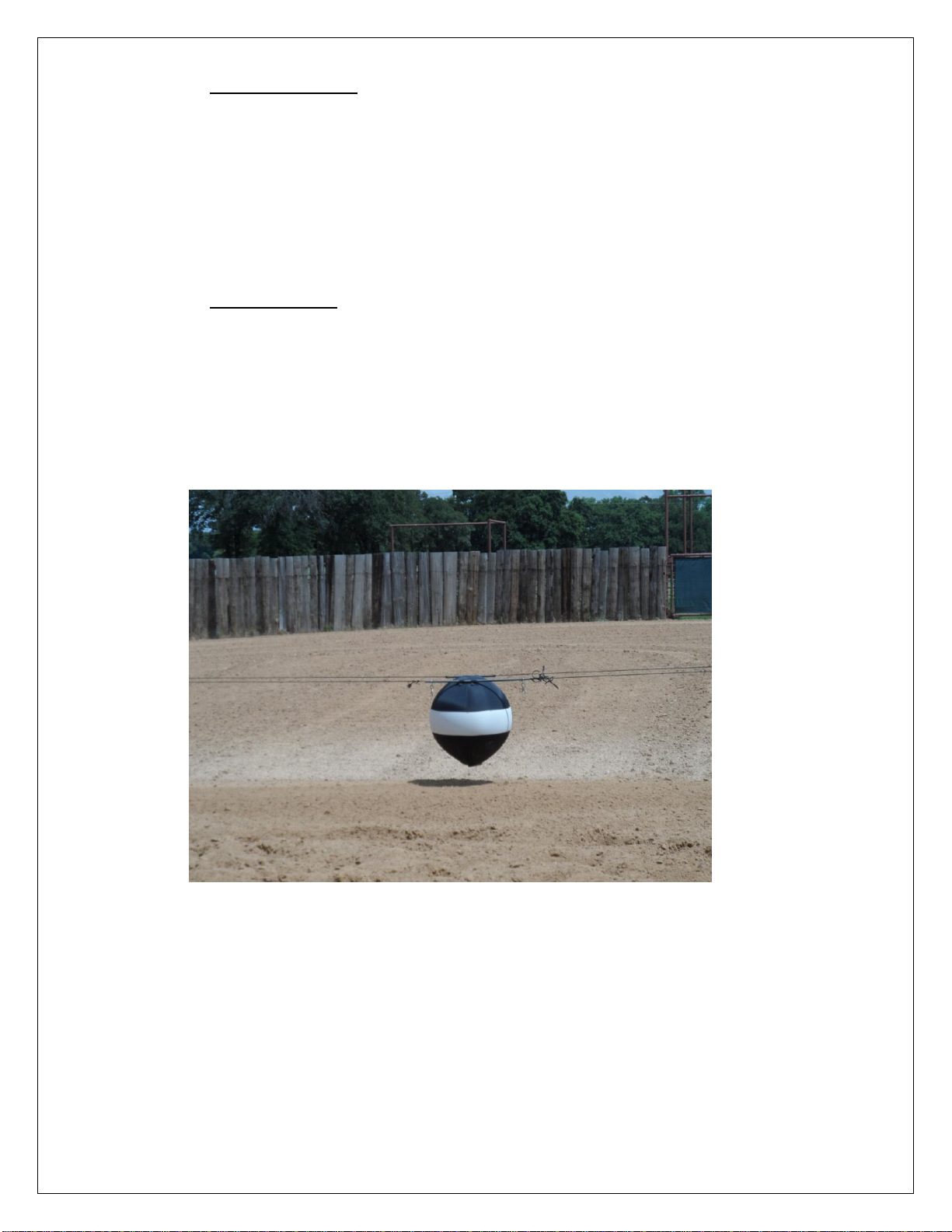
Completed Installation

Operating Instructions:
Following is a brief description of the various switches and dials:
1. POWER: Flip POWER switch ON to energize control box.
Red POWER light will illuminate. The unit requires 5 seconds to
initialize. Avoid pressing any control buttons while unit initializes.
2. MANUAL: Operate control box left, right, and change speeds.
3. LOGIC: Switch reverses the direction that the “Eye Ball”
travels.
Example: After the Pro Cutter is installed, attach remote control to
your wrist (wrist watch position) and button assembly on index
finger. Press left switch with your thumb. If the “Eye Ball” travels
left, you’re ready to go. However, if the “Eye Ball” travels right,
toggle LOGIC switch. This will cause the “Eye Ball” to travel left
as you press left switch –and right as you press right switch.
4. FUSE: Power surges, faulty cord, or defective component may
cause a fuse to blow. When this happens, remove fuse and replace
using only 4 amp/250v AGC fuse, or permanent damage may result.
NOTE: power indicator light will not illuminate when fuse is bad.
5. SPEED DIALS: Front face of control box
SPEED 1: The left speed dial is the starting speed. When the
control box is asked to run using either remote or manual control
switches, the “Eye Ball” will begin moving at Speed 1 regardless
of direction. To stop, simply release button or switch.
SPEED 2: The right speed dial is second speed. To access
Speed 2, begin by pressing a run button on remote or manual
control. The “Eye Ball” will begin moving at Speed 1. When
traveling at Speed 1, release button and re-press immediately.
Control box will shift to Speed 2. Repeat and control box will go
back to Speed 1.
EXAMPLE: Set Speed 1 (left dial) to "15", and Speed 2 to "45".
When a run button is pressed, the “Eye Ball” will move at
SPEED 1. To shift to SPEED 2, start the “Eye Ball” moving at

SPEED 1, then release and instantly re-press run button. The
“Eye Ball” will now travel at SPEED 2.
NOTE: When you stop, the unit automatically resets to
SPEED 1.
NOTE: If the unit fails to shift to, double-click
was not fast enough. User only has 100
milliseconds to cause speed change.
6. REMOTE CONTROL: The remote control can be worn in a variety
of ways depending on comfort and convenience. The most common
method is to strap the control pouch to your preferred wrist in a wrist
watch position. The two run buttons are installed on the side of your
index (pointer) finger. The riders thumb is then used to operate the run
buttons.
7. PRACTICE:Attach remote control to your wrist by inserting your
hand through Velcro loop on pouch. Attach switch plate to index finger
and rotate buttons so they can be pushed by your thumb. Walk to
center of arena and practice operating machine. Make any necessary
adjustments. Once comfortable with the controls, you are ready to
introduce your horse to the Pro Cutter. We recommend working at
slow speeds until both horse and rider are acclimated.
ADDITIONAL FEATURES:
* Soft-start acceleration: Progressive acceleration ramp
* Superior radio system: Better range, less interference.
* Large drive system: Heavy-duty industrial components
* Weather-tight NEMA enclosure
* Climate control system
* Dynamic braking
Thank you for choosing............
SHOW PRO INDUSTRIES
P.O. Box 1235, Springtown, TX 76082 / (817)523-4055 / (817)220-5117 fax

IMPORTANT SAFEGUARDS
1. Electrical enclosure (control box) should be protected with a non-metal roof or
shield. This not only protects the paint finish but also keeps rubber components
(gasket, boots, antenna, etc.) from drying out.
2. Warning: Electric shock or malfunction could occur if power cord or plug is
damaged in any way. Do not work Pro Cutter in rain –or allow cord or plug to
lie in water
3. Always use properly grounded 120VAC electrical outlet.
4. Do not operate Pro Cutter if control box, or any of its components are damaged
in any way, or after malfunction.
5. Use Pro Cutter only as intended and described in literature.
6. Always unplug Pro Cutter when through working each day.
7. Do not allow flag to run into ends, or damage may occur to electronics, rope, or
both.
TROUBLESHOOTING
Problem: Solution:
1. Pro Cutter will not operate Make sure there is power to
using remote control or manual machine. Check 4A fuse.
switch.
2. Pro Cutter will operate using Check battery in remote
manual switch but not remote control. Be sure antenna &
control. receptacle aren’t damaged.
3. There’s a “clicking” noise Fuse may be blown or a more serious
problem may exist. Contact
Show Pro Industries.
NOTE: The remote control, worn on the rider’s wrist, has a 9-volt battery in the plastic
case inside the pouch. The battery must be changed on a regular basis. The first sign that
a battery may be failing is when the cow or flag starts hesitating or “missing” going one
direction. The natural tendency is to press harder on the switch, twist the cable leading to
the switches, or tap the remote control, all of which may result in damage. Avoid these
conditions and replace battery at first sign of intermittent operation. Remote control
should always be stored indoors.
NOTE: The antenna or rubber cap must be securely fastened to receptacle on top of
control box at all times. If the antenna or antenna cap is removed or damaged, water can
enter the control box resulting in severe damage to electronics.

LIMITED WARRANTY
Show Pro Industries
PO Box 1235
Springtown, TX 76082
(817)523-4055 / (817)220-5117
The following warranty is in lieu of all
other warranties, expressed, implied or
statutory, including but not limited to any
implied warranty of merchantability or
fitness for a particular purpose.
All new products sold by Show Pro Industries are warranted
against defects in material and workmanship for two (2) years
from the date of original purchase. During the warranty period,
Show Pro Industries will repair, or at its option replace without
charge, any SPI product (excluding normal wear items), providing
it is returned to the factory, shipping prepaid, and is proven to be
defective during the subsequent factory inspection. The warranty
period for products repaired after expiration of new product
warranty, as stated above, is limited to the repair portion and is
valid for 90 days from date of reshipment to customer. All
warranties, expressed or implied, are void if product is damaged
by accident, misuse or modification in the absence of written
authority from Show Pro Industries.
Table of contents
Popular Farm Equipment manuals by other brands

Gregoire Besson
Gregoire Besson Tetra 3001 L operating instructions

MASCAR
MASCAR Diavel 630 Use and maintenance manual

Cima
Cima Link Maintenance Instruction

Giltrap
Giltrap Construction 17 Operations & parts manual

AGCO
AGCO Massey Ferguson 9702 Service manual

Kongskilde
Kongskilde R 655 DS Operator's manual


