matev MOW-H/M 160 CM User manual

Modifications and errors excepted!
Version: 2020-17-11
Reference number: BA-MOW-32068
matev GmbH
Nürnbergerstr. 50
90579 Langenzenn, Germany
Tel.: +49 (0) 9101 90870
Front Mower
MOW-HM 140/160/190 CM
Operating Manual

Modifications and errors excepted! Version: 2020-29-09
Table of contents
Table of contents ...................................................................................................................2
1Introduction .......................................................................................................................4
2About this operating manual..............................................................................................5
3Technical data...................................................................................................................6
Power diagram, hydraulic.........................................................................................7
4General safety notices.......................................................................................................8
Presentation of the general safety notices................................................................8
Intended use ............................................................................................................8
Instructions for the owner.........................................................................................9
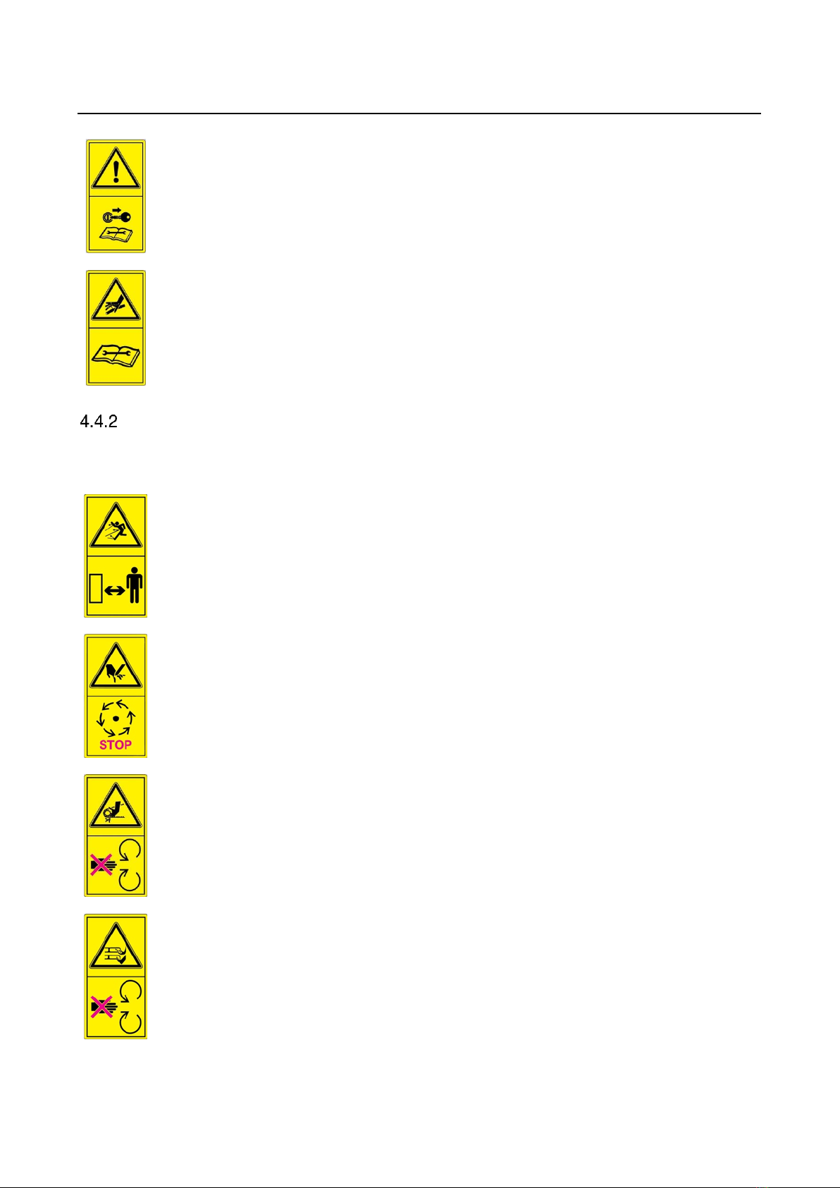
Warning signs ..........................................................................................................9
Safety devices........................................................................................................11
5Equipmentvariants...........................................................................................................20
Basic implements with rigid or hydraulic driving frame............................................20
Optionally required accessories..............................................................................20
Required accessories.............................................................................................22
Optional accessories..............................................................................................22
6Operation of the mower...................................................................................................24
Application area .....................................................................................................24
Function.................................................................................................................24
Instructions for mowing ..........................................................................................24
7Installation.......................................................................................................................26
Operation of the mower..........................................................................................29
Secure the mower for road travel to the work site...................................................30
Adjusting the mower incline....................................................................................31

Page 3
Adjusting the cutting height for the rigid driving frame ............................................33
Adjusting the cutting height on the hydraulic frame.................................................34
Moving the mower into maintenance position.........................................................35
Adjusting the air supply..........................................................................................37
Securing the lawn harrow for road travel to the work site........................................38
Move the lawn harrow into transport position..........................................................38
8Maintenance....................................................................................................................42
Safety when performing maintenance ....................................................................42
Maintenance...........................................................................................................42
Cleaning and care..................................................................................................44
Lubricating schedule ..............................................................................................45
9Fault................................................................................................................................48
10Repair .............................................................................................................................49
11Disposal ..........................................................................................................................50
12Warranty..........................................................................................................................50
13List of illustrations............................................................................................................51
14List of tables....................................................................................................................51
15EG –Declaration of Conformity.......................................................................................52

1
Page 4
1Introduction
We welcome you to the matev family
and thank you for purchasing a matev GmbH product, we appreciate your trust. You have acquired
a quality product, if contrary to expectations you should have problems with the implement, contact
your responsible sales partner.
Before using the product for the first time, please read this operating manual carefully and consci-
entiously all the way through. The manual describes the handling of the implement in detail and will
support you in working safely and effectively.
For damage that occurs due to improper use, we will not accept any warranty claims.
Variants may be described in the manual that do not match the scope of delivery of your imple-
ment.
Please enter the data of the rating plate on the implement in the manual. This information will be
helpful in communication if there is a service case.
The matev products are subject to change in the interest of technical progress. All information, il-
lustrations, and technical specifications represent the latest status at the time this manual was pub-
lished. The manufacturer reserves the right to make changes at any time in the interest of technical
progress.
Regards
matev GmbH
Company stamp –sales partner

2
Page 5
2About this operating manual
Prior to first use, read the manual carefully and conscientiously all the way through.
Keep this manual where it is easily accessible. This will enable you to refer to important information
and handling instructions as needed.
At transfer of the machine the owner of the machine receives instruction in the operation and
maintenance of the machine from the owner's sales partner.
The owner must ensure that operating and maintenance personnel have been instructed in full
scope in the operation and maintenance of the machine.
Listings with bullet points are marked as follows:
•Text
•Text
•Text . . .
Handling instructions are marked in the sequence, in which they should be executed, as follows:
1. Text
2. Text
3. Text . . .
If directions (left, right, rear, front) are specified in the operating manual, these directions are al-
ways based on the direction of travel of the carrier vehicle.
The direction of travel of the front PTO shaft is always specified from the front as viewed from
above. Right rotation CW (clockwise), left rotation CCW (counterclockwise).
Fig. 1: Definition of alignment and direction of rotation

3
Page 6
3Technical data
Technical data
MOW - 140 CM
MOW - 160 CM
MOW - 190 CM
Dimensions (L/W/H) in mm
1,343x1,425x535
1,452x1,625x535
1,564x2,146x535
Cutting width
1370 mm
1570 mm
1870 mm
Cutting height from - to
With hydraulic frame
X
28 mm - 97 mm
X
Cutting height from - to
With rigid frame
15 mm 135 mm
28 mm - 119 mm
15 mm 135 mm
Required minimum capacity of
the carrier vehicle
From 23 hp / 17 kW
From 23 hp / 17 kW
From 34 hp / 25 kW
Gear oil / lubricating grease
Gearbox fill quantity
0.4 l
0.8 l
0.8 l
Gear oil
Viscosity class 90, e.g. Shell Spira MB90
Gear oil change
After the first 50 h, then every 500 h
Lubricating grease
All purpose grease with a temperature resistance from -30 °C to +130
°C, for example, mineral-based, lithium universal lubricating grease or
similar products.
Possible drive configuration
Front PTO shaft
1,000 rpm CW/CCW
2,000 rpm CW/CCW
Hydraulic
X
38 - 42 l/min
43 - 47 l/min
X
43 - 47 l/min
48 - 52 l/min
Weight / tire pressure
Weight, at least
202 kg
246 kg
277 kg
Tire pressure
1.5 bar
Table 1: Technical data

3
Page 7
Power diagram, hydraulic
Please use the diagram below to assess whether your vehicle has enough hydraulic power availa-
ble.
1. Add the power specifications of all options present on your machine.
2. Be aware of the information concerning the hydraulics of your vehicle.
As a rule, the hydraulic power of your vehicle that is available for additional
implements, is considerably lower than the engine power.
3. Enter the information in the table below: Example: maximum hydraulic pressure
on the vehicle 150 bar. Oil volumetric flow of 40 l/min. equals a maximum hy-
draulic power of 8.8 kW.
Fig. 2: Hydraulic power diagram

4
Page 8
4General safety notices
Guidelines and instructions that you must comply with when dealing with machines are presented
in this section.
Presentation of the general safety notices
The safety notices used in the text employ pictograms and signal words, which in combination indi-
cate the severity of the risk to be expected.
Dangerous situations that can directly result in severe
or fatal injuries.
Dangerous situations that can possibly result in minor injuries or material
damage.
Recommendations or information for the operator.
Read this note. It facilitates your work.
Intended use
To avoid misuse, also read section 6, Operation of the mower, all the way
through.
•The implements are designed for municipal tractors, i.e. carrier vehicles.
•They must only be operated on carrier vehicles with the power range specified in the tech-
nical data.
•Intended use also includes compliance with the operating, service, and maintenance condi-
tions prescribed by the manufacturer.
•Moreover, intended use includes exclusive use of original spare parts and supplemental
equipment, or use of such parts and equipment that meet the technical requirements speci-
fied by the manufacturer.
•Unauthorized modifications to the implements result in exclusion of liability on the part of
the manufacturer.
All other uses are excluded!
Non-intended use causes:
•Danger of injury to the operator or third parties
•Carrier vehicle damage or implement damage
•Environmental damage

4
Page 9
Instructions for the owner
Qualifications of personnel
Installation and maintenance tasks involving safety-relevant parts must only be executed by per-
sonnel with the following qualifications:
•They must have a technical education, such as agricultural machine mechanic, auto me-
chanic, etc.
•Persons without qualified training must be supervised by a person with qualified training.
•They must have read and understood this operating manual.
•They must be aware of the relevant safety regulations (accident prevention).
Accident prevention
The safety regulations and accident prevention regulations are legally regulated in every country.
The workshop manager or the appointed specialist for occupational health and safety is responsi-
ble for compliance with the valid regulations.
Instruction
At transfer of the implement the owner receives instruction in the operation and maintenance of the
implement from the sales partner.
The owner must ensure that operating and maintenance personnel have been instructed in full
scope in the operation and maintenance of the implement.
Warning signs
Warning signs indicate hazards that cannot be countered through protective measures. To avoid
severe or fatal injuries the warning signs must always be obeyed.
Missing warning signs must be replaced without delay.
Do not operate the implement if the warning signs are missing.
You can order the warning signs by specifying the spare parts numbers listed
in section 4.5.2 (no. V000...).
General warning signs
In this section the non-specific, generally-valid warning signs are explained.
Read the operating manual and comply with the safety notices.

4
Page 10
Prior to performing maintenance and repair tasks, turn off the engine
and remove the key.
Injuries due to fluid escaping under high pressure.
Comply with the notice in the operating manual.
Machine-specific notice
Machine-specific warning signs and instructions concerning operation and maintenance of the ma-
chine are explained in this section.
Danger due to ejected parts when the engine is running
–maintain a safety distance!
Only touch machine parts after they have come to
a complete standstill!
Do not open or remove protective devices when the engine is running.
During operation, maintain a sufficient distance to the mowing blade!

4
Page 11
Implement is only suitable for a PTO shaft speed of 2000 rpm!
Predominantly mid-mount, front, or independent engine PTO shafts.
Implement is only suitable for a PTO shaft speed of 1000 rpm!
Usually an independent engine PTO shaft.
Implement is only suitable for clockwise PTO shaft rotation! (CW)
Implement is only suitable for counterclockwise PTO shaft rotation! (CCW)
The direction of rotation is always specified when viewing the end of the PTO shaft from the front
(see Fig. 1 page 5).
Do not operate the mower without discharge guard or suction port!
After each use re-tighten all screws
Lubricating point
Safety devices
There are various safety devices on machines to protect people when working with a machine, or
who are in the direct vicinity of the machine, to prevent premature wear, and also to prevent envi-
ronmental damage. These safety devices are a fixed component of the machine and must not be
manipulated or removed. Missing or damaged safety devices must be replaced without delay.
Concerning the safety devices, a distinction is made between protective devices that prevent con-
tact with a danger point, and safety notices that alert to a hazard on the machine.
Likewise, hazards can occur through insufficient maintenance; consequently the maintenance in-
structions must also be classified as safety notices

4
Page 12
Each time before starting to drive, ensure that all described safety notices
and protective devices are completely present and functional. Do not operate
the implement if safety notices or safety devices are missing or damaged.
Protective device on the machine
Protective cover
Universal joint shaft
Protective cover
Gearing stub (drive)
Protective cover
Universal joint shaft
Fig. 3: Protective cover for gearbox

4
Page 13
Belt guard
(Drive)
Fig. 4: Belt guard (drive)
Adapter fixation on
the front lift
Attention!
The attachment variant is
different depending on the
carrier vehicle
Fig. 5: Adapter fixation on the front lift

4
Page 14
Standard equipment:
Side discharge cover.
Fig. 6: Side discharge cover
Optionally available:
Port with suction hose
Fig. 7: Port with suction hose

4
Page 15
Optionally available:
Mulch insert for mower
Fig. 8: Mulch insert for mower
Optionally available:
Rear discharge without
suction unit
Fig. 9: Rear discharge without suction unit

4
Page 16
Rear discharge with
suction unit
Fig. 10: Rear discharge with suction unit

4
Page 17
Safety notices on the machine
Attention
After each use re-
tighten all screws!
Order no. V0 002 965
Read the safety in-
structions
Order no. V0 002 922
Switch off engine
Order no. V0 002 922
Fig. 11: Warning sign on the right attachment bracket
Lever position for
maintenance position
Order no. V0 002 966
Fig. 12: Warning sign on the left attachment bracket

4
Page 18
Attention! Discharge guard
Order no. V0 002 955
Stop Turbine
Order no. V0 002 920
Thrown-out parts
Order no. V0 002 966
Matev
Order no. V0 002 966
Fig. 13: Warning sign on the basic deck (right side discharge)
Direct of rotation left
Order no. V0 002 930
Drive shaft
Order no. V0 002 930
Max. rpm 2000
Order no. V0 002 930
Fig. 14: Warning sign on the basic deck (right side discharge rear)

4
Page 19
Mower blades
Order no. V0 002 928
Fig. 15: Warning sign –mower blades
Do not remove protective
device
Order no. V0 002 928
Fig. 16: Warning signs

5
Page 20
5Equipmentvariants
Basic implements with rigid or hydraulic driving frame
Basic implement –rigid driving frame
Available as MOW 140, MOW 160, MOW 190
Basic implement with hydraulic driving frame
Available as MOW 160
Optionally required accessories
Attachments
Attachment –Cat. 0
Cat. 0 available for MOW 140, MOW 160, MOW 190
Cat. 1N available for MOW 160, MOW 190
Cat. 1 available for MOW 160, MOW 190
Cat.1 available for MOW 160, MOW 190
Cat. 1 with quick catch hook available for MOW 160, MOW 190
Mower inserts
Side discharge mower insert
Available for MOW 140, MOW 160
This manual suits for next models
3
Table of contents
Other matev Farm Equipment manuals
Popular Farm Equipment manuals by other brands

Husky
Husky 230-00-00-000 operating instructions

Duncan
Duncan Uni-Seeder owner's manual

360 Yield
360 Yield 360 Y-DROP HAGIE DELTA BOOM instruction manual

Kamikaze
Kamikaze KV 4 manual

OUTDOOR DISTINCTIONS
OUTDOOR DISTINCTIONS Bloomz Box installation instructions

Stocks AG
Stocks AG Turbo Jet 8 VS-2 Original Operating Manual and parts list