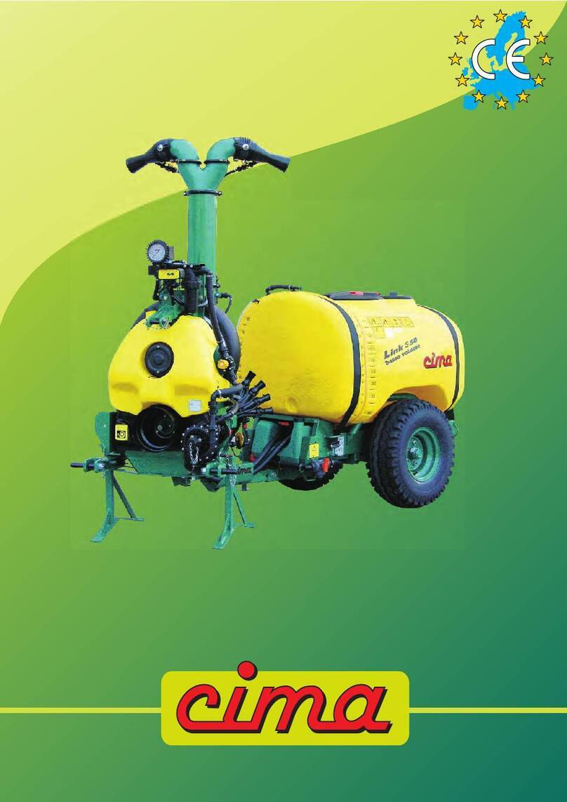
Cima Link Operating and maintenance instructions

Link
Operation and maintenance instructions

Dear Customer, thank you very much!
We want to congratulate with you, for hav-
ing chosen a sprayer.
Your choice shows the wisdom of the
well-informed Purchaser, aware of the
fact, that the required features of quality,
technique and reliability must be satisfied
at the right price!
Our continuous engagement in R&D and
in testing our machines allows us to re-
alize products able to offer the best per-
formances, a high reliability and a great
easiness of use at the same time !
Our first goal, is to get our Customers
happy for having met us!
The “Spare parts catalogue” of this sprayer/
sprayhead is available in the “restricted area” on
website www.cima.it.
In order to accede, use:
User name: sprayer
Password: 844719KE

OPERATION AND
MAINTENANCE INSTRUCTIONS
Model: ...................................................
Serial Number: .....................................
(Pubblication N° LUM-LINK-07-EN)
© CIMA S.P.A. 1996 - 2017 Private property.
Any reproduction, even if partial, is forbidden if not preventively authorized in writing by the Cima S.p.A. company.
Articulated sprayer
Link


Rev.07 - Jan. 2017 III
Link 50-55
LISTING OF VALID PAGES
This publication consists of 100 pages, subdivided as follows:
N° OF PAGE REVISION BASE
from I to VI 07 January 2017
from 1 to 4 07 January 2017
ADDITIONAL RECORDS AND VARIANTS
REVISION DESCRIPTION
00 First Edition, March 2001
01 Second Edition, January 2002
02 Third edition, March 2002
03 Fourth edition, July 2003
04 Fifth edition, January 2009
05 Sixth edition, March 2001
06 Revision, April 2012
07 Revision, January 2017
09
10

Rev.07 - Jan. 2017
IV
Link 50-55
INDICE GENERALE
1 FOREWORD .......................................................................................................................... 1
1.1 CHECKS TO BE CARRIED OUT AT MATERIAL RECEPTION ..................................................1
1.2 PUBLICATION IDENTIFICATION ........................................................................................ 1
1.3 ATTACHED PUBLICATIONS ................................................................................................ 1
1.4 PURPOSE OF PUBLICATION ............................................................................................. 1
1.5 REFERENCE TO REGULATIONS ....................................................................................... 2
1.6 USING THE MANUAL ........................................................................................................... 2
1.7 UPDATES...............................................................................................................................2
2 GLOSSARY ........................................................................................................................... 3
2.1 TERMINOLOGY .................................................................................................................... 3
2.2 ABBREVIATIONS .................................................................................................................. 3
2.3 DECALS ................................................................................................................................. 3
3 GENERAL INFORMATION ................................................................................................... 8
3.1 MACHINE IDENTIFICATION ................................................................................................ 8
3.2 TECHNICAL ASSISTANCE .................................................................................................. 8
3.3 SAFETY NOTICES ................................................................................................................ 8
3.3.1 General ................................................................................................................................... 8
3.3.2 Precautions against the fi res ................................................................................................... 9
3.4 SAFETY SYSTEMS ............................................................................................................ 10
3.5 HANDLING OF AGRO-CHEMICALS ................................................................................. 10
3.5.1 Storage ................................................................................................................................. 11
3.5.2 Specifi c equipment ................................................................................................................ 11
3.5.3 Disposal of empty containers and agro-chemicals residues ................................................. 11
3.5.4 Personal Protective Equipment (PPE) ................................................................................. 12
4 MACHINE’S STRUCTURAL ANALYSIS ............................................................................ 13
4.1 FRAME ................................................................................................................................. 14
4.2 FAN SERVO AMPLIFIER .................................................................................................... 18
4.3 HYDRAULIC CIRCUIT ........................................................................................................ 19
4.3.1 Operating principle ................................................................................................................ 19
4.3.2 Hydraulic circuit components ................................................................................................ 23
4.4 TECHNICAL DATA .............................................................................................................. 37
4.4.1 Sprayer dimensions and weights ..........................................................................................37
4.4.2 Weight of accessories ........................................................................................................... 38
4.4.3 Centrifugal pump CD32 ........................................................................................................ 40
4.4.4 Filters .................................................................................................................................... 41
4.4.5 Tanks ..................................................................................................................................... 41
4.4.6 Fans ...................................................................................................................................... 41

Rev.07 - Jan. 2017 V
Link 50-55
5 COUPLING MODALITIES .................................................................................................. 42
5.1 HITCHING TO THE TRACTOR .......................................................................................... 42
5.2 MOUNTING OF THE TRANSMISSION SHAFT ................................................................43
5.3 INSTALLATION OF REMOTE CONTROLS ...................................................................... 43
5.3.1 Electrical control panel - E10 ................................................................................................43
5.3.2 Manual 2-tap distributor - P9 (for the versions where foreseen) ........................................... 45
5.3.3 E.P.A. Control Unit ................................................................................................................ 45
6 DISTRIBUTION DEVICES ................................................................................................ 46
7 ACCESSORIES ................................................................................................................... 47
7.1 FILLING PIPE ...................................................................................................................... 47
7.2 HYDRAULIC SWIVELLING DEVICE ................................................................................. 47
7.3 ROTARY BLADES’ HYDRAULIC MIXER (PATENT N° 1295858) .................................... 48
7.5 REAR LIGHTS KIT .............................................................................................................. 48
7.6 EPRESSURE ELETTROREGULATOR .......................................................................... 48
7.7 E.P.A. KIT - DELIVERY PROPORTIONAL ADVANCEMENT ........................................... 49
8 FILLING ...............................................................................................................................50
8.1 FOREWORD - USE OF THE FAN DISENGAGEMENT ................................................... 50
8.1.a Disengagement of the fan ..................................................................................................... 50
8.1.b Fan engagement to perform the treatment ........................................................................... 51
8.2 FILLING THROUGH POURING FROM THE TOP ............................................................ 51
8.3 FILLING WITH THE SPECIFIC PIPE ................................................................................ 52
9 AGITATION ......................................................................................................................... 55
10 OPERATING PROCEDURES ............................................................................................ 55
10.1 PRELIMINARY OPERATIONS TO TREATMENT ............................................................. 55
10.2 PREPARATORY OPERATIONS TO TREATMENT ........................................................... 56
10.3 THE TREATMENT ............................................................................................................... 57
10.4 PROCEDURE TO WASH THE HYDRAULIC CIRCUIT .................................................... 58
10.5 END OF TREATMENT - STORAGE ................................................................................... 60
10.5.1 Daily ...................................................................................................................................... 60
10.5.2 End of seasonal cycle ........................................................................................................... 61
11 TANK AND HYDRAULIC CIRCUIT DRAINING ................................................................. 63
12 LIFTING AND TRANSPORT............................................................................................... 64
12.1 LIFTING AND TRANSPORT OF THE SPRAYER ............................................................. 64
12.1.1 Trailed cart disengagement ................................................................................................... 64
12.1.2 Lifting of the fan servo amplifi er assembly ............................................................................66

Rev.07 - Jan. 2017
VI
Link 50-55
12.1.3 - Lifting of the trailed cart ....................................................................................................... 66
13 MAINTENANCE OPERATIONS ......................................................................................... 67
13.1 LUBRICATION ..................................................................................................................... 67
13.2 FAN SHAFT SUPPORT OIL LEVEL CHECK .................................................................... 68
13.3 FAN SHAFT SUPPORT OIL REPLACEMENT .................................................................. 68
13.4 CLEANING OF FILTER’S CARTRIDGE ............................................................................ 69
13.5 FAN BELT TENSIONER ..................................................................................................... 69
13.6 PUMP BELT TENSIONER ................................................................................................. 70
13.7 MAIN TANK FASTENING BELT ......................................................................................... 70
13.8 TABLE OF MAINTENANCE OPERATIONS ...................................................................... 71
14 FAULTS FINDING .............................................................................................................. 72
15 REPAIRS ALLOWED .......................................................................................................... 75
15.1 REPLACEMENT OF PUMP CONTROL BELT .................................................................. 75
15.2 REPLACEMENT OF ELECTRICAL PANEL’S FUSES ..................................................... 76
15.3 PRESSURE GAUGE REPLACEMENT ............................................................................. 76
15.4 INSPECTION AND CLEANING PUMP FILTER ................................................................ 77
15.5 TANK LEVEL GAUGE CLEANING ..................................................................................... 78
15.6. CHECK HYDRAULIC DELIVERY ...................................................................................... 79
15.6.1 Check with fl owmeter ............................................................................................................ 79
15.6.2 Check without fl owmeter ....................................................................................................... 80
15.7 TANK REMOVAL OR REPLACEMENT ............................................................................. 81
15.8 REPLACEMENT LAMPS REARLIGHTS ........................................................................... 82
16 INTEGRATIVE DIAGRAMS ................................................................................................ 83
16.1 HYDRO-PNEUMATIC DIAGRAM ....................................................................................... 83
16.2 WIRING DIAGRAM ............................................................................................................. 87
17 NOISE LEVEL ...................................................................................................................... 92
18
ATTACHMENT: DECLARATON OF CONFORMITY
................................................................... 93
19 WARRANTY ......................................................................................................................... 94
19.1 GENERAL INFORMATION ................................................................................................. 94
19.2 REPORTING DEFECTS IN GOODS ................................................................................. 94
19.3 TO PASS SAFETY INFORMATION ................................................................................... 94
19.4 VALIDITY AND ACCEPTANCE .......................................................................................... 94

Rev.07 - Jan. 2017 1
Link 50-55
1 FOREWORD 1
1.1 CHECKS TO BE CARRIED OUT AT MATERIAL RECEPTION
At reception of the machine, make sure that this one is complete and in good condition in every part.
If any damaged parts are found out, timely inform about that the machine Distributor, or directly contact
C.I.M.A. SpA.
Upon receipt of the machine, expressly verify the following conditions:
- that the machine is delivered assembled in all its parts, and that the equipment fully complies with
the requested confi guration (that procedure is necessary, because for overall dimensions’
requirements the machine is often partially disassembled during the transport);
- that the connections are correctly mounted;
- that the cable clamps are correctly tightened, as well as all the fi ttings and connections;
- that all the protections are both present and fi rmly fastened;
- that the oil level inside the fan support is correct;
- that the fan, the fan protection casing or other parts of the machine ARE NOT damaged because
of any bumps suff ered during the transport.
1.2 PUBLICATION IDENTIFICATION
The “OPERATION AND MAINTENANCE INSTRUCTIONS” manual is an integrative part of the sprayers.
It is identifi ed by a Publication No. located on the frontispiece, and through which the document can
be identifi ed, traced and/or subsequently referred to.
The information elements contained herein are updated as at the date of publication. C.I.M.A. S.p.A.
reserves the right to modify its machines without notice, with the purpose of applying technical
enhancements, and it declines all responsibility for possible omissions from the publication.
All rights are reserved. No parts of this book may be reproduced or utilized in any form or by any means,
electronic or mechanical, including photocopying, recording, or by any information storage and retrieval
system, without permission in writing by C.I.M.A. S.p.A..
1.3 ATTACHED PUBLICATIONS
- Spare parts catalogue, available in the “restricted area” on website www.cima.it
(see on the inside cover);
- Distribution devices, “Operation and maintenance instructions”;
- Distribution devices, “Spare parts catalogue”;
- “Low Volume - Instructions for sprayer adjustment”.
1.4 PURPOSE OF PUBLICATION
All indications contained in this manual are aimed at the user of the sprayer.
The duration of the machine and its operation, the operator’s safety and the respect for the environment
are dependent upon scrupulous observance of the stated norms.
Before making use of the sprayer, the user must read, understand and abide by all regulations listed
in this manual.

Rev.07 - Jan. 2017
2
Link 50-55
1.5 REFERENCE TO REGULATIONS
This manual was set out conforming to the regulations contained in following documents:
— Directive 2006/42/CE: Attachment 1 point 1.7.4;
— UNI 10653: Technical Documentation;
— UNI 10893: Technical Documentation.
1.6 USING THE MANUAL
Read every part of this manual, paying attention to the WARNING and DANGER indications both on
the text and on the machine or on components.
All operations suggested by the manual will have to be followed with the utmost care and only after
having understood the negative consequences of improper usage.
The following “symbols” are used within the text in order to highlight and visually identify the importance
of the various types of information:
Indicates important additional information.
Non observance can result in permanent damage to the sprayer.
Highlights possibly dangerous situations to people.
The manual, with relevant attachments and possible integrating issues, must be kept with the utmost
care and must always be complete, integer and legible in every part. Should it be mislaid it is imperative
to immediately request a duplicate from C.I.M.A. S.p.A.
Should the decals originally applied on the machine be mislaid, damaged or become incomprehensible,
they should be promptly replaced.
For every type of distribution device (Head) delivered with the sprayer, a specifi c user and maintenance
manual is attached. All the head manuals must always accompany the one of the machine.
- The manual must always be kept for the sprayer’s whole operational life.
- Any modifi cation received must be permanently inserted in this publication.
- The manual must be ceded with the sprayer should this be sold.
1.7 UPDATES
Any amendments or additions that C.I.M.A. S.p.A. may send the sprayer’s owner will be accompanied
by the necessary instructions to be included with this publication, becoming an integral part of it.

Rev.07 - Jan. 2017 3
Link 50-55
2 GLOSSARY 2
2.1 TERMINOLOGY
The terms FRONT, REAR, RIGHT and LEFT utilised in this publication refer to the sprayer as seen
by an operator from behind the operative unit along the drive line and facing it: the rear part of the
machine is that closest to the operator and the front part is the one that gets attached to the tractor.
2.2 ABBREVIATIONS
cm .................................................................................................................................... centimetres
g ................................................................................................................................................grams
h ................................................................................................................................................. hour
ha ............................................................................................................................................hectare
ha/h .......................................................................................................................... hectare per hour
kg .......................................................................................................................................... kilogram
kg/cm2 .......................................................................kilograms per square centimeter (atmosphere)
km ........................................................................................................................................ kilometre
km/h .....................................................................................................................kilometres per hour
l .................................................................................................................................................... litres
l/h ..................................................................................................................................litres per hour
l/min .......................................................................................................................... litres per minute
Lm .............................................................................................................................. width in metres
m ............................................................................................................................................... metre
Mesh ..................................................................................................... N° of meshes per linear inch
Micron ................................................................................................................ 1/1000 of millimetre
mm .................................................................................................................................... millimetres
PPE ................................................................................................... Personal Protective Equipment
PTO .............................................................................................................................power take-off
RPM ............................................................................................................................revs per minute
s ............................................................................................................................................. seconds
2.3 DECALS
The safety and use/maintenance decals are applied to the machine are described in the following
paragraph.
Every decal is marked with its part number, in case it needs to be replaced.
The arrangement of the adhesives on the machine is shown in the following pictures.

Rev.07 - Jan. 2017
4
Link 50-55
Safety decals
95001
95098
95099
95008
95015 95010
95009
- STOP THE ENGINE AND REMOVE THE KEY FROM THE
TRACTOR’S CONTROL PANEL BEFORE CARRYING OUT ALL
MAINTENANCE OR REPAIR OPERATIONS
- CONSULT THE USER AND MAINTENANCE MANUAL BEFORE
USING OR INTERVENING ON THE MACHINE
- DANGER OF SPRAYS: KEEP AT A SAFE DISTANCE
- DANGER, PARTS IN MOTION. BEFORE REMOVING PROTECTION
GUARDS, STOP THE TRACTOR, REMOVE THE KEY FROM THE
TRACTOR’S CONTROL PANEL AND ENSURE THAT ALL MOVING
PARTS HAVE STOPPED.
- NO HAND-
WASHING
TANK
- OPERATING SPEED OF
THE DRIVE OUTLET
(PTO):
540 RPM
- DANGER: GLOVES
MUST BE USED TO
EMPTY THE TANK
- BEFORE UTILISING THE RELEASE
DEVICE, STOP THE TRACTOR,
REMOVE THE KEY FROM THE
TRACTOR’S CONTROL PANEL
AND ENSURE THAT THE FAN HAS
STOPPED.
- CONSULT THE USER AND MAINTENANCE MANUAL
BEFORE USING THE MACHINE
- DANGER OF CONTAMINATION BY CONTACT OR
POISONOUS PRODUCTS INHALATION
- IT IS FORBIDDEN TO GET INTO THE TANK!
95021
- LIFTING:
USE ONLY SUITABLE BELTS
AND TO HOOK AT THE POINT
INDICATED

Rev.07 - Jan. 2017 5
Link 50-55
Use and maintenance decals
95065
2,7 atm
95081
95081
95080
- INDICATIONS ON
THE OPERATION
OF THE PLANT-
WASHING TAP (P15)
95086
95059
- WARNING: NEVER OPERATE
THE SPRAYER WITHOUT
LIQUID IN THE TANK
- INDICATION ON THE
OPERATION OF THE
3-WAY TAP (P2)
- HOOKING POINT
FOR THE LIFTING
OF THE MACHINE
95060
- TIRES PRESSURE
95079
95115
- CHECK THE OIL LEVEL EVERY 8 HOURS:
FAN SHAFT BEARINGS.
- HAND
WASHING
TANK TAP
Imprint next to
the tap.
- GREASE EVERY 200 HOURS:
WHEEL HUBS AND ARTICULATED
JOINTS
95100
- INDICATION ON THE
OPERATION OF MIXER
TAP (P12)
- LUBRICATE EVERY
200 HOURS:
SUPPORT FOOT with
crank regulation
95024
95058
- INDICATION OF
THE CHEMICAL
EMPLOYED
FOR THE
TREATMENT
- GREASE YEARLY:
FAN TIGHTENER SUPPORT AND
FREEWHEEL
95054
2
95019
95019
- FILL ONLY WITH
CLEAN WATER
Hand washing tank fi ller,
Rinsing tank fi ller.

Rev.07 - Jan. 2017
6
Link 50-55
Positioning of the safety, use and maintenance decals
NOTE: The numbers with the asterisk (*) indicate the adhesives relevant either to optional
components or to accessories to be applied ONLY on the models and versions on which
it is foreseen.
95005
SUPPORT FOOT
95059
95065
95015 (*)
FAN TIGHTENER
SUPPORT
95115
9501095001
95080
95009
95059
FREE WHEEL
01680_1
01681
95102
95021
2
95019
95019
95019
95100
95008
2
95019
95054
95115

Rev.07 - Jan. 2017 7
Link 50-55
95059
95079
ARTICULATED
JOINTS AND
TRAIL EYE
95054
01683
MOZZI RUOTE
95081
95095
95054
2,7 atm
95081
95021
95098
95059
95086
95021

Rev.07 - Jan. 2017
8
Link 50-55
3 GENERAL INFORMATION 3
3.1 MACHINE IDENTIFICATION
00620
00070
Identification nameplate
®
MONTU BECCARIA (PV) ITALY
(39) 0385/246636 FAX 246637
S.p.A.
Fabbr.
nel.
Matr.
Tipo
Peso a V. Kg Peso T.Kg
Press.
max bar
3.2 TECHNICAL ASSISTANCE
C.I.M.A. S.p.A. is at the complete disposal of customers for any type of intervention. The names and
addresses of its service network, both in Italy and in foreign countries, can be requested from:
C.I.M.A. S.p.A. - 27040 Montù Beccaria - Loc. Molino Quaroni (PV) - ITALIA
tel. +39-0385-246636 - fax +39-0385-246637
e.mail [email protected]
GPS: 45°03’19.3” N - 9°18’22.1” E
3.3 SAFETY NOTICES
3.3.1 General
The personnel appointed to the use of the machine must have acquired an exhaustive
knowledge of the same one and of the dispositions contained inside this publication, be
able to properly interpret the symbols of the adhesives applied on the machine, and, in
addition, perfectly know the safety and the work hygienic rules in force in the country
where the machine itself is to be used.
All the preparation, use, maintenance, moving and transporting operations must be carried out of the
regulations contained in this publication.
IT IS FORBIDDEN TO UTILISE THE SPRAYER FOR PURPOSES OTHER THAN FOR ITS
INTENDED USE, SINCE IT WAS MANUFACTURED ONLY FOR SPRAYING AGRICULTURAL
CROPS WITH ANTI-PARASITIC PRODUCTS.
ANY USE OTHER THAN THOSE DESCRIBED IN THE USE PERMITTED IS CONSIDERED
AS NOT CONFORMING AND THEREFORE IS NOT PERMITTED.
It is necessary to scrupulously abide by the following general norms:
— check that the weight and power of the tractor are compatible with the sprayer to be used;
— verify that the tow capacity of the tractor is compatible with the total weight of the sprayer to be
used;

Rev.07 - Jan. 2017 9
Link 50-55
On the identifi cation plate, the full-load weight (PESO T.) of the machine is indicated,
measured WITHOUT the distribution device, and WITHOUT the accessories possibly
installed.
In order to calculate the weight on the hoister in operative conditions (at full load), add to
the WEIGHT OF THE FAN SERVO AMPLIFIER (see Paragraph 4.4.1 - Sprayer dimensions
an weights), the WEIGHT OF THE DISTRIBUTION DEVICE which is used (see “Distribution
devices – Use instructions” manual), THE WEIGHT OF THE INSTALLED ACCESSORIES
(Par. 4.4.2) and THE 50% OF THE WEIGHT OF THE USED CARDAN SHAFT (see the
relevant specifi c manual).
In order to calculate the towed weight in operative conditions (at full load), add to
the weight indicated on the identifi cation plate (PESO T.), the weight of the installed
accessories (Par. 4.5.2 - Weight of the accessoires).
— before utilisation, check the correct tightening and securing of the machine’s various components,
paying particular attention to the safety protections and to the moving parts;
— only utilise protected cardan shafts provided with CE conformity certifi cation.
Carry out the assembly only if the drive outlets of both tractor and sprayer are equipped with the
protection counter-guard;
— check that the cardan shaft is blocked by the appropriate anti-rotation chains;
— keep people and animals away from the machine before starting it up;
— don’t wear articles of clothing that might get caught in moving parts;
— keep to a low speed while negotiating bumps or crossing ditches.
— during the use of the machine, the operator must have a suffi ciently good visibility on the working
areas, consequently it is recommended to keep both clean and effi cient the cab windows and the
rear-view mirrors;
— actuate the parking brake when the tractor is stopped on a slope and place the wedges behind
the wheels of the railed cart;
— always stop the tractor’s engine and actuate the parking brake before carrying out any operation
on the sprayer;
— never leave the machine unguarded, when the key is inserted inside the tractor control panel;
- All maintenance and repair operations must be carried out only after having rinsed the
tank and fl ushed the system.
- Before operating within the tank it is necessary to wash it thoroughly with clean water.
- The application of paints and/or solvents, the washing of closed environments and
machinery as well as the utilisation of the air fl ow for purposes other than those
expressly concerning the spraying of agro-chemicals is not permitted.
- It is forbidden to enter the tank.
3.3.2 Precautions against the fi res
Don’t approach either fl ames or heat sources to the machines. The materials used for manufacturing
the machine itself are made by widely using oil derivatives: tanks, pipes, wheels, plastic components;
besides, the presence of lubricants and of chemical product residuals make them potentially fl ammable.
- It is forbidden to use the machine within a potentially explosive environment.
- It is forbidden to perform welding operations if ammonium salts were previously used.

Rev.07 - Jan. 2017
10
Link 50-55
3.4 SAFETY SYSTEMS
All machine moving parts are suitably protected by guards and highlighted through the use of warning
decals.
- It is forbidden to use the machine with these guards removed.
- Before removing the protection, stop the tractor’s engine and remove the key from the
control panel.
The pictures illustrate the machine’s guarded parts:
01681
FAN DISENGAGEMENT
REMOVABLE PROTECTION COVER
(for the version where foreseen)
PTO
PROTECTION CASING
PROTECTION COVER FOR
FAN SERVO AMPLIFIER
FAN PROTECTION GRILL
THE OWNER AND/OR THE OPERATOR OF THE SPRAYER ARE NOT PERMITTED TO
MODIFY THE STRUCTURE OR THE SPECIFIC OPERATION OF THE SPRAYER ITSELF. ANY
REPAIRING INTERVENTION HAS TO BE CARRIED OUT EITHER AT THE DEALERS’ OR AT
THE C.I.M.A. S.p.A. AUTHORIZED WORKSHOPS, OTHERWISE ANY KIND OF WARRANTY
IMMEDIATELY CEASES AND C.I.M.A. S.p.A. IS CLEARED OF ANY CONSEQUENT AND/
OR IMPLIED RESPONSIBILITY.
3.5 HANDLING OF AGRO-CHEMICALS
The operator could become contaminated due to accidental spray, contact or inhalation of products
or crop-spraying mixtures.
The environment could become polluted by mixture over-spills, puncturing of containers, uncontrolled
storage of used and unwashed containers or spillage into waterworks.
In order to avoid these risks the preparation and fi lling operations must be carried out in suitably ap-
pointed and adequately equipped sites.
01685
01686

Rev.07 - Jan. 2017 11
Link 50-55
To use pesticides (purchase, transport, loading, treatment planning, mixture
preparation, fi eld transfert, treatment performance, ending treatment liquid waste
management, equipement rinsing and waste disposal) you must follow the country
rules.
Absolutely respect the rules on the label of the product used referring to the dose for
hectar and to the compatibility of other products.
3.5.1 Storage
Fixed / stationary: the site used must be well ventilated and secured by lockable doors in order to
prevent even accidental access by children or unauthorised persons.
Mobile: the carrier equipment must be properly locked and kept under conditions whereby access
by children or unauthorised persons can be prevented during the absence of the operator. All full or
partially utilised containers must be secured against tipping, falling or breakage during transportation.
Both types of storage must:
— have a suitable container for the storing of empty packaging materials should a specifi c storage
area not be available;
— have a clean water supply readily available for washing, by means of a specifi c container or through
connection to the waterworks system;
— have the use of fi re extinguishers, should fl ammable products and substances be stored.
- All packages, whether whole or partially utilised, must be stored in their original
packing and with the warning instructions clearly displayed and legible.
- The storage indications must always be scrupulously adhered to, as well as their
utilisation and possible disposal as suggested on the product’s original packaging.
3.5.2 Specifi c equipment
The site at which the preparation and fi lling out will take place must provide for:
— all the equipment necessary to the precise measuring of both the water quantity and the dose of
product to be mixed in the tank at every fi lling;
— all the equipment and means useful to the preparation of the mixture and for the cleaning of the
operator in case of contamination;
— all tools necessary to facilitate the direct introduction of the agro-chemicals in the tank;
— the allocation of clothing and specifi c equipment in order to avoid contamination by contact or
inhalation during the whole operative phase of the intervention;
— the availability of proper equipment able to stop the uncontrolled spilling and fl owing of the mixture;
— a retaining valve on the feed pipe when the fi lling of the tank takes place directly from the waterworks
system.
3.5.3 Disposal of empty containers and agro-chemicals residues
Agro-chemicals are classifi ed as “special” waste and their disposal must take place separately from
“urban” wastes.
Empty packaging and contaminated containers to be done away with cannot be
dispersed, burned or buried. The washing water for the cisterns and the tools utilised
for the preparation of mixtures cannot be emptied on the ground, spilled into the
sewage system or in waterways and rivers.

Rev.07 - Jan. 2017
12
Link 50-55
The disposal of special wastes is regulated by specifi c norms. In order to perform this operation it is
necessary to obtain the relevant information from the Local Offi ces specifi cally appointed to rule on
this subject. The non compliance with these regulations can cause considerable damage to persons
and animals as well as polluting the environment.
3.5.4 Personal Protective Equipment (PPE)
The use of phytosanitary products might imply a more or less high chemical risk for the workers on
the basis of the toxicity and the dangerous properties of the phytosanitary product, of the level and
duration of the exposure, of the absorption level through the respiratory tract, the skin, the mucosa
and the ingestive tract, as well as the way and frequency of the use.
The “personal protective equipment” (PPE) are equipment that all the users of the machine need to
wear and hold in order to be protected by one or more risks that are capable to treath the security or
healthy during the job.
Regarding the basic requirements, PPE have to:
- be suitable to the risks that have to be prevented, without causing major risks themselves;
- be suitable to the existing conditions on the workplace;
- consider the ergonomic (easily adaptable, easy to wear and safe) or health needs for any users;
- be adaptable to the user according to his/her needs.
The PPE for the protection against dangerous chemical agents used for the operations that concern
the exposition to phytosanitary products , pertains to the third class (3rd class – 0000).
Use solely PPE equipped with the
needed CE mark, in the scrupulous
rispect of the regulations in force in
the country where the machine is in
use and adequate to the phytosanitary
product used.
It’s needed to use the PPE in each of the following
working stage:
- tank fi lling and addition of the phytosanitary
product;
- spraying,
- calibration of the sprayer,
- draining and cleaning of the tank,
- phytosanitary product replacement,
- servicing.
The following must be worn:
- for the protection of the body (gloves, suits, boots),
- for the protection of the respiratory tract, of the head and of the eyes (helmet, masks, fi lters, glasses,
hoods and headdresses).
Filters must be replaced following the producers’ instructions, and in any case:
- in case a bad smell is noticed;
- in case a resistance to the respiratory function is noticed;
- at least once a year in case of occasional use.
For ALL PPE in use, follow the use instruction declared by the PPE producerse.
00073
Other manuals for Link
2
Table of contents
Other Cima Farm Equipment manuals