Showa Denki FUMERESA FRM-H15 User manual
1. Safety precautions ・・・・・・・・・・・・・・・・・・・・・・・・・・・・・・・・・・・・・・・・・・・・・・・・・・・・・・・・・・・・・・・・・
1
2. Item to check at product delivery ・・・・・・・・・・・・・・・・・・・・・・・・・・・・・・・・・・・・・・・・・・・・・・・・・・・・・
1
3. Name of each parts ・・・・・・・・・・・・・・・・・・・・・・・・・・・・・・・・・・・・・・・・・・・・・・・・・・・・・・・・・・・・・・・・・
2
4. Specificaton ・・・・・・・・・・・・・・・・・・・・・・・・・・・・・・・・・・・・・・・・・・・・・・・・・・・・・・・・・・・・・・・・・・・
2
5. Precautions ・・・・・・・・・・・・・・・・・・・・・・・・・・・・・・・・・・・・・・・・・・・・・・・・・・・・・・・・・・・・・
3
6. Operation ・・・・・・・・・・・・・・・・・・・・・・・・・・・・・・・・・・・・・・・・・・・・・・・・・・・・・・・・・・
3
7. Maintenance and inspections ・・・・・・・・・・・・・・・・・・・・・・・・・・・・・・・・・・・・・・・・・・・・・・・・・・・・・・・・・・・
4-5
8. About disposal ・・・・・・・・・・・・・・・・・・・・・・・・・・・・・・・・・・・・・・・・・・・・・・・・・・・・・・・・
5
9. Troubleshooting ・・・・・・・・・・・・・・・・・・・・・・・・・・・・・・・・・・・・・・・・・・・・・・・・・・・・・・・・・・・
6
10. Warranty・・・・・・・・・・・・・・・・・・・・・・・・・・・・・・・・・・・・・・・・・・・・・・・・・・・・・・・・・・・・・・・
6
11. Contact information・・・・・・・・・・・・・・・・・・・・・・・・・・・・・・・・・・・・・・・・・・・・・・・・・・・・・・
6
0522(E)-B
Thank you for purchasing Fumeresa from Showa Denki. This manual explains the specifications for
the [Fumeresa FRM-H15].
Please read the oprating instruction and cautionary information carefully to ensure that the Fumeresa
is used in a safe and efficient manner. Special attention should be given to cautionary information
which bears [ ] the mark.
Fume Collector for Welding
Operation Manual & Cautions
Keep this manual in a secure location where it can be easily
accessed
【Contents】

●Verify that the delivered product (model, etc.) is the same with the ordered item.
●Verify that the product has not been damaged or deformed, etc., during shipment.
●Verify is there a missing item to the components of the machine.
Please store the machine as the following environment condition.
・Indoor, please avoid direct sunlight
・Temperature between 0℃~40℃
・Humidity between 10%~90%(No condensation)
When storing or unused for a long time (more than 3 months), it is recommended covering the machine with vinyl or
similar in the dry place with little temperature change.
Caution
This unit is dry type. Do not use for inhale fume that contain a large amount of
water or oil. It may cause premature clogging of the filter.
Do not drop, strike or crush filters used in this machine.
It may cause dust leakage.
2. Item to check at product delivery
Although all our products are thoroughly tested and inspected prior to shipment, nonetheless the customer should check
the following items after delivery.
Wear protective equipment such as gloves and dust masks when cleaning this
machine or replacing the filter.
1. Safety precautions
Warning
indicates that there is a possibility of [an accident leading to death
or serious injury] or [fire occurrence] if mishandled.
Caution
indicates things that lead to [accident leading to injury] and
[product damage] if mishandled.
Warning
Careless use of this machine could result in serious injury or accidents.
This machine is intended to collect welding fumes. Do not use to inhale
flammable solvents, oil, cigarettes with fire, etc., as they may cause a fire.
Also, do not suction powder material such as plastic, aluminum, magnesium,
etc. that may explode.
This unit is not explosion proof. It can not be used in explosive atmospheres.
No. No.
① ⑥
② ⑦
③ ⑧
④ ⑨
⑤ ⑩
200V or 380V It is not shared.
50Hz or 60Hz It is not shared.
1 piece
Hood opening (initial)
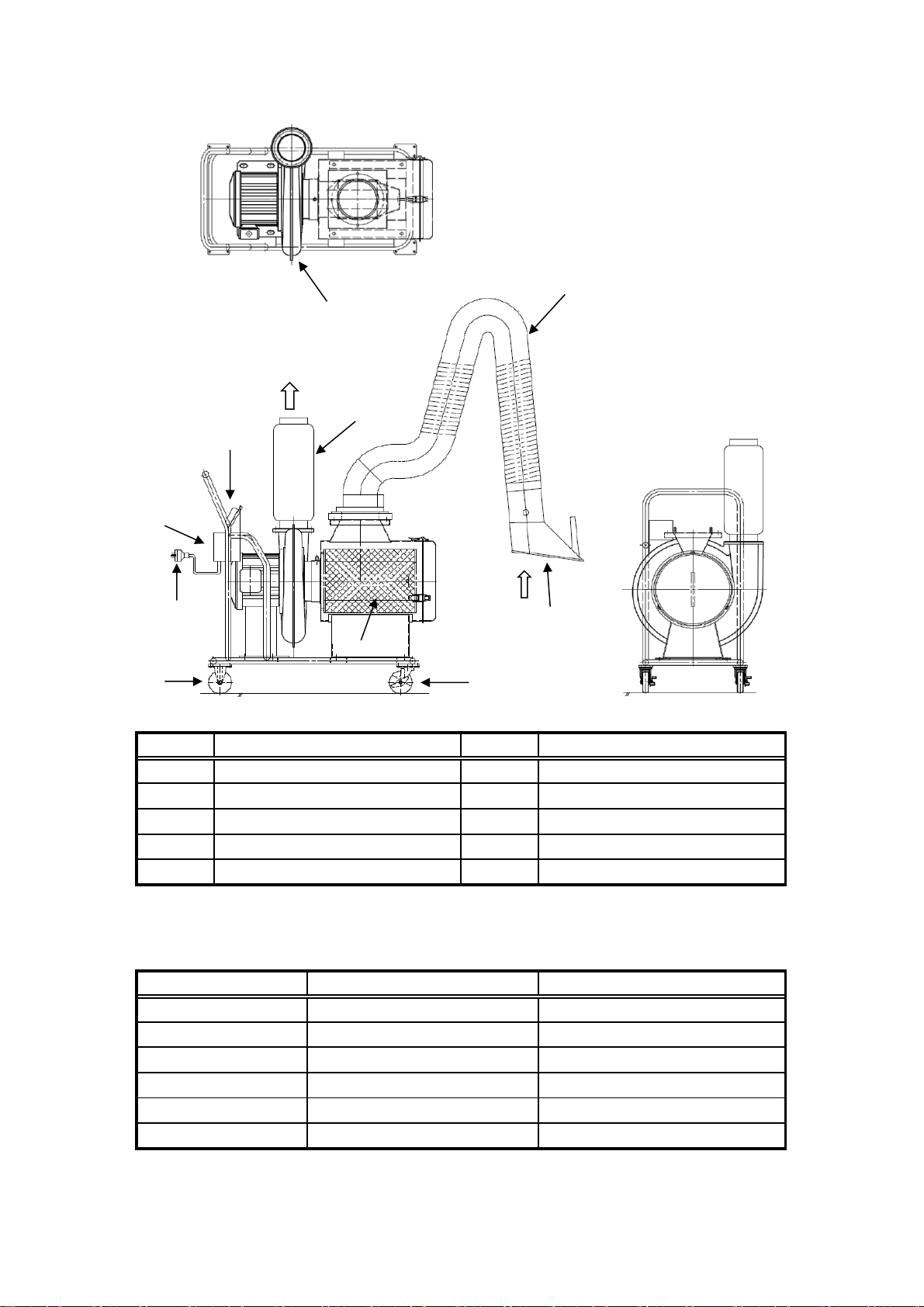
3. Name of each parts
Name
Blower
Name
Plug
Flexible arm
Silencer
Caster rear wheel
Caster front wheel (with stopper)
Manometer
Switch box (with thermal protector)
Tank
Hood
4.Specifications
FRM-H15
Notes
11m/s
1.5kW 2P
200V or 380V
Model
Suction velocity
Motor
Voltage
50Hz or 60Hz
Cotton cartridge filter
Approx. 100 kg
Frequency
Filter
Weight
⑨
①
②
③
④
⑥
⑦⑧
⑩
⑤
IN
OUT

(1) Please install indoor horizontal location. Do not get water or oil.
(2) Do not move while the flexible arm extended
(3) Please check the manometer value and clean the filter regularly. ※For the cleaning method, please refer to
page 4 section [7. Maintenance and inspection (2) Filter cleaning and replacement method]
(4) The heat resistance temperature of the flexible arm about 70 ° C. If the inhale air exceeding the heat
resistance temperature for a long time, the duct will be deformed.
※When the duct is deformed, it may form a gap or suction may be decreased.
(5) If unused for a long time, please unplug from the outlet for safety reason.
Also, fix the caster (front wheel) with a stopper.
※Be sure to fix the left and right (2 places) casters with stoppers.
(6) If you feel that the machine is abnormal (such as burnt, heated, or high sound), stop operation immediately
and unplug.
(7) This model is divided into 2 types: 50 Hz-only machine and 60 Hz-only machine. Please use the product that
match with your frequency.
(8) Do not modify this machine by yourself. It may cause damage.
(9) This unit is not explosion proof. It can not be used in explosive atmospheres.
(10) When moving the machine with an overhead crane etc., remove the silencer and sling it on.
※Please check the following items before use.
(1) Connect the plug into the outlet
※If the outlet capacity is less than 20A, the breaker or fuse may break
(2) Make sure that the manometer guideline (black) points to “0”.
(3) Turn on / off the switch and check that the blower is rotating clockwise (as viewed from the motor side).
※ In the case of reverse rotation, suction will not be performed, and the needle of the manometer will be close
to “0”.
※Please see page 5[7. Maintenance Inspection (5) Phase change method of switch box]
(4) Turn on the "switch" and check that there are no leaks or abnormal noise in any part.
(1) Please install this machine in any place. ※ Please fix the caster with stopper.
(2) Turn on the switch and let it suck welding fumes.
(3) If you want to move the weld, please set the hood according to the location.
※ The suction capacity increases as it gets closer to the welding point, but if it is too close, will be inhaling
the shielding gas, etc., which may affect the welding strength.
※When moving the flexible arm, please operate with the handle on the hood. Pulling any part other than the
handle may cause damage.
(4) Continuous operation is possible, if you follow the procedure above.
(1) Please turn off the switch.
(2) Please store the flexible arm and cable, will not interfere with the passage.
5.Precautions
6. Operation
[Preparation]
[Operation]
【Stop】

7. Maintenance and inspections
(1)
1) Make sure that the suction port of the hood is not blocking by dust or foreign matter.
It may cause the suction capacity decrease.
2) Do not use the duct part that has damage or deterioration.
3) If the hood or the duct do not stay at an optional position, tighten the bolt and nut of the link
assembly (joint part) in the duct of the flexible arm.
※If it is too tight, it may not work.
(2) Filter cleaning and replacement method
1) When the manometer needle (black) reaches the red pointer, it is time to clean the filter.
①Open the tank cover.
※There is a latch next to the patch lock. Release the lock while pressing the latch.
②Turn the wing nut of the filter section and remove the filter.
③Insert the jet gun (air gun) from the front (packing side) of the filter.
※Use the gun nozzle with the nozzle facing downward. If it is horizontal or upward, dust will
be scattered.
④Clean in accordance with the filter cleaning direction shown in Fig.1.
⑤After cleaning the lower surface, rotate the filter and repeat steps ③to ④
⑥Cleaning is complete when the filter rotates once.
⑦Insert the filter after cleaning and tighten the wing nut to fix
it.
※If the tightening is weak, fumes will leak from the outlet.
⑧Attach the tank cover.
1)
①
②
③
④
2)
(3)
environment.)
※If the filter is covered with the moisture of oil smoke or mist, replace it immediately regardless of its
lifespan.
※If the filter lifespan has reached, but the air volume has not decreased, the replacement time can
optionally delay.
※If the filter is damaged, replace it immediately regardless of its lifespan.
The filter lifespan is approximately 1 year or 2,000 hours. (Varies depending on usage conditions and
Filter lifespan
Turn the wing nut of the filter section and remove the filter.
※There is a latch next to the patch lock. Release the lock while pressing the latch.
Insert a new filter and tighten the wing nut to secure.
Attach the tank cover.
※If the tightening is weak, fumes will leak from the outlet.
Flexible arm
When you discard filter, please follow the regulations of your region.
【Replacement method】
The filter is cartridge type. The exchange procedure is as follows.
【Cleaning method】
※In some cases, even if the filter is clogged, the manometer needle may not reach the red pointer.
※Please read the instruction manual attached separately and use it properly.
Open the tank cover.
【Fig. 1】Filter cleaning direction

(4)
1) Make sure that the needle (black) points to "0" when the switch is off.
If did not point to "0", adjust with the "zero set knob" in Fig. 2.
2)
The ponter (red) is set to approximately 1.5 kPa. (initial stage)
When changing, please adjust with "Pointer adjustment knob".
(5) Switch box phase change method
1) Turn the switch box knob and remove the cover.
※The wiring on the primary side and secondary side is in the order of red(R), white(W) and black (B).
(initial stage)
2) Swap red and black on the primary side wiring, to this order: black, white, red.(Fig. 3)
※There is a yellow crossover wire at the left side of the terminal, just tighten it with the black wire.
3) Set the cover on the switch box and turn the knob to fix it.
(6)
1) If the machine will unused for a long time (more than half-year), please clean the filter.
※Weld fumes may stick to the filter and hardened, and will hard to remove even after cleaning.
2) High water or oil content in welding fumes will reduce filter lifespan significantly.
3) This machine filter is dry type. It cannot wash in water.
4)
Set the air pressure for filter cleaning to 0.4 to 0.5 kPa.
8.About disposal
Please follow laws and regulations when disposing of the product.
How to adjust the manometer
Another important points
【Fig. 2】Manometer
Hose mounting port
Pointer(Red)
Zero set knob
Needle (black)
Pointer adjustment knob
Primary side
Secondary side
RWB
RWB
BWR
RWB
【Fig. 3】Switch box internal structure
※When the filter is new, fumes may leak from the discharge port, but this is normal
(1) Scope of warranty
When a malfunction occurs even if operating the unit according to the inctruction manual and the caution on
the attachment labels, etc. within the warranty period, we will repair the failure for free.
However, if this unit is assembled into the customer's other equipment, expenses for removal from the
equipment and attachment to the equipment, accompanying work expenses, transportation costs, and other
indirect damages cost such as opportunity or operational loss of customers are beyond the scope of warranty.
(2) Warrranty period
The warranty perod shall be one year from delivery.
(3) Even within the scope of warranty, the following cases shall require charge for repair in principle.
①Malfunctions and damages due to wrong use contrary to the cautions in the instruction manual,
attached labels, etc. or improper repair and modification.
②Malfunction and damages due to transportation, dropping, etc. after purchase.
③Malfunctions and damages due to fires, earthquake, wind and flood damages, other disasters,
abnormal voltages, use of unspecified power supply (voltage and frequency), etc.
④Malfunctions and damages due to repair and modification (including drilling into the unit) by third
parties.
⑤Malfunction and damages due to use of parts other than those specified by us.
⑥Malfunctions and damages due to mixing in offoreign materials.
⑦Discoloration and flaws from age detoration or from long-term use and malfunctions due to natural
consumption of consumable parts.
(4) Damages caused by malfunctions occuring during use of this unit shall not be indemnified.
(5)
The above points are specified based on use in Japan. When using this unit in countries other than Japan, consult
with our branches or sales offices in advance.
11.Contact information
(1) Contact the following department regarding specifications and technical questions.
Showa Denki CO., LTD, Daito Factory, Business Promotion Dept.
TEL: +81-72-870-5708
FAX: +81-72-870-7243
E-mail: [email protected]
(2) If the unit malfuctions or requires repair, contact our nearest branch or sales office on the back cover. At that time,
inform us of the type and manufacturing (No.) on the plate.
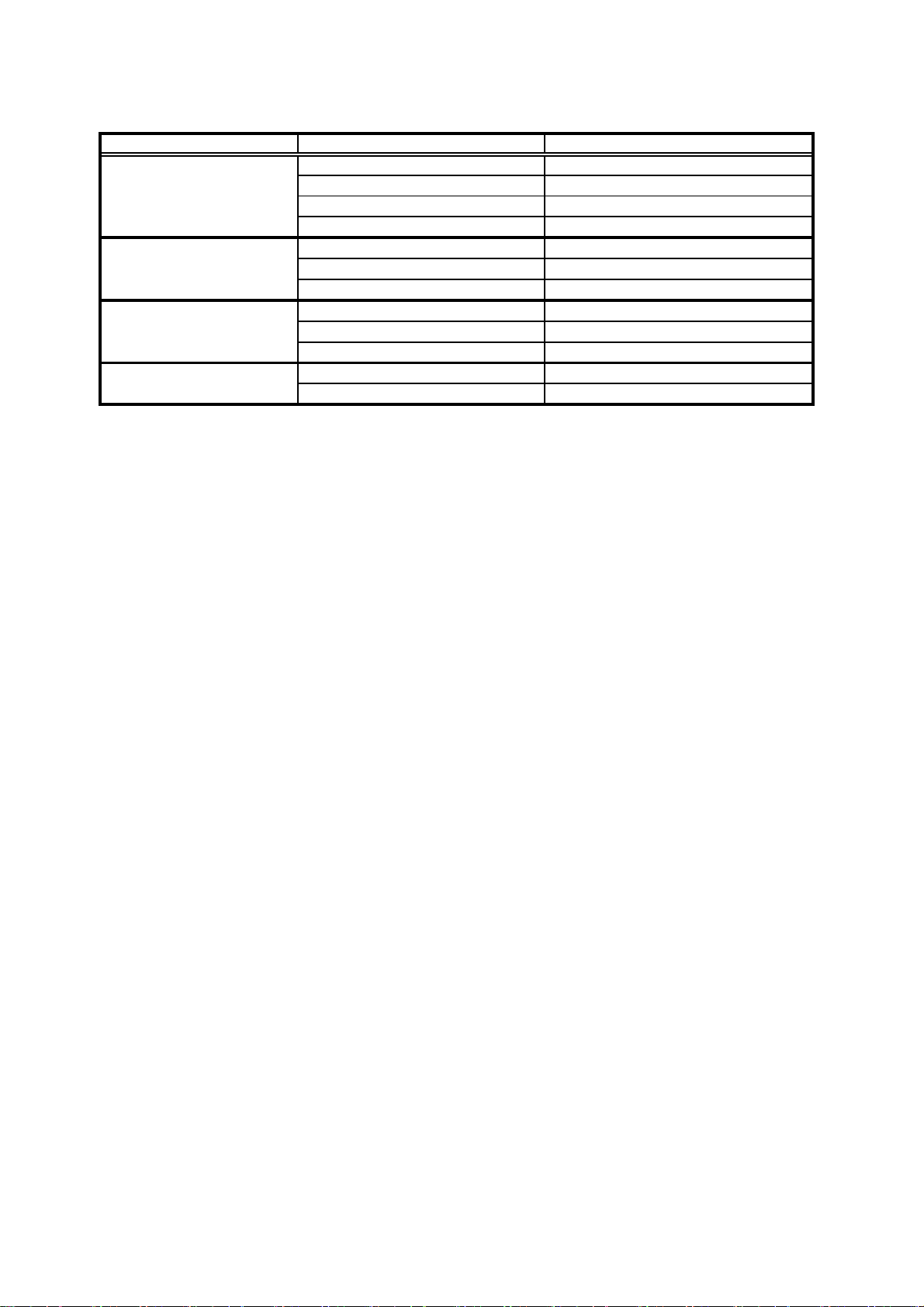
9.Troubleshooting
Malfunction status, situation
Probable cause and confirmation items
Insufficient suction power
Product body damaged
Filter cleaning / replacement time
Clogged hood
Reverse phase operation
Safety measures and treatment
Please clean and replace the filter
Please (request) repair
Please match the phases (see Page 5)
Please remove dust and foreign matter
Manometer does not move
can not turn on
Power cable disconnection
Plug connection failure
Hose connection failure
Reverse phase operation
Please replace the manometer
Manometer damage
Please set the hose again
Please replace the power cable
Please plug into the outlet properly
Please match the phases
Please replace the filter with a new one
10.Warranty
Filter installation defect
Fume leaks
Loose screw in switch box
Filter damage
Please tighten the screw
Please install properly

Oversea Sales Department
1-25 Shinden Kitamachi, Daito City, Osaka 574-0052
☎+81-72-871-1511 FAX +81-72-870-7243
SHOWA DENKI (THAILAND) CO., LTD
No1/46 Soi2 Grand De Ville, Soi Supapong 1 (Soi Srinakarin 42), SriNakarin Road Nongbon, Pravet Bangkok, Thailand 10250
☎+66-2-330-8798 FAX +66-2-330-8799
SHOWA DENKI (KOREA) CO., LTD.
31094 A-710 Cheonan Mirae Ace High Tech City,10, Baekseokgongdan 1-ro, Seobuk-gu, Cheonan-si, Chungcheongnam-do,Korea
☎+82-41-906-5710 FAX +82-41-906-5720
SHOWA DENKI (TAIWAN) CO,. LTD
No.82, Liaoyang 4th Street, Beitun Dist.,Taichung City 406, Taiwan
☎+886-4-2241-3005 FAX +886-4-2241-3006
http://www.showadenki.co.jp
CAD data is available on this website
1-25 Shinden Kitamachi, Daito City, Osaka 574-0052
Table of contents
Other Showa Denki Dust Collector manuals


