Showa Denki Chiko CKU-060AT3-ACC User manual

チコーエアーテック株式会社
CHIKO AIRTEC CO., LTD.
•取扱説明書(以下、本書といいます)の『製品使用上のご注意』の内容をよく理解し、本書をよく読んでか
ら操作してください。
Please understand well the contents of "Cautions on Product Use" of Instruction Manual
(hereinafter referred to as “this manual”), and operate it after often reading this manual.
•本書はいつでも使用できるよう、大切に保管してください。
Please keep this manual carefully to be able to use it at any time.
日
本
語
English
ヒュームコレクタ
Fume Collector
型式/MODELS
CKU-060AT3-ACC (100V)
CKU-060AT3-ACC(-T)(200V)
CKU-060AT3-ACC(-CE)(220-230V)
取扱説明書
Instruction Manual
051(E)-A
■転載・複写について/Copyrights
•本書の著作権は、チコーエアーテック株式会社が所有しています。
CHIKO AIRTEC CO., LTD. owns the copyright of this manual.
•本書の内容の一部あるいは全部の無断転載や複写は固くお断りします。
Unauthorized reproduction or copying of part or all of the content of this manual is strictly prohibited.
•本書の内容は、将来予告なく変更することがあります。
The contents of this manual are to change without notice.
© 2020 CHIKO AIRTEC CO.,LTD.
■はじめに/Introduction
このたびは、お買い上げ頂き、誠にありがとうございます。
チコーエアーテック株式会社は「風の技術」を有効に利用し、コンパクトに空気をクリ-ンにすることをテ-マと
して努力しております。
この製品は、この風の技術をコンパクトにまとめた省エネ形のクリ-ン BOX です。
長期間故障なく安全にご使用いただくために、この取扱説明書をよくお読みいただき、本機の性能を十分に発
揮できますよう正しいお取扱いをお願いします。
We greatly appreciate that you have purchased our dust collector.
CHIKO AIRTEC CO., LTD. is working to achieve clean air with compact equipment while utilizing “air
technology” effectively.
This machine is an energy-saving-type clean box that realizes “air technology” in a compact body.
Please read this instruction manual thoroughly and handle this machine correctly so that you can use it
safely for a long time and enjoy its full performance.
■本文中の表記について/About Notation
本書では、以下の表記に従って説明しています。
This manual explains according to the following notations.
表記/Notation
意味/Description
重要
IMPORTANT
本機の機能を十分に発揮するための情報や、本機の損傷を防ぐための情報を記載し
ています。
The information for fully exhibiting the function of this machine and the information
for preventing damage to this machine are indicated.
メモ
NOTE
参考となる情報を記載しています。
The information which is consulted is indicated.
1. 2. 3. ・・・
操作手順を記載しています。
The operating procedure is indicated.
参照先を記載しています。
The reference destination is indicated.

CMN011-006 原本 (Original instructions) 1
English
Table of contents
Chapter 1 Product Usage Precautions.............................................................................3
1.1 Safety Notations .............................................................................................................................. 3
1.2 Precautions for Transport, Storage, and Relocation
................................................................................ 3
1.3 Precautions for Installation.............................................................................................................. 3
1.4 Precautions for Operation ............................................................................................................... 4
1.5 Other Precautions ........................................................................................................................... 4
1.6 Safety Label Locations .................................................................................................................... 5
Chapter 2 Components Identification ..............................................................................6
2.1 Accessories ..................................................................................................................................... 6
2.2 Device Body .................................................................................................................................... 7
2.2.1 CKU-060AT3-ACC................................................................................................................... 7
2.3 AT3 Panel ........................................................................................................................................ 8
2.4 Display Indications .......................................................................................................................... 9
2.4.1 About Modes............................................................................................................................ 9
2.4.2 Indications During Stoppage ................................................................................................... 9
2.4.3 Indications During Operation................................................................................................. 10
Chapter 3 Operation ........................................................................................................11
3.1 Start-up Preparation.......................................................................................................................11
3.1.1 Installation ..............................................................................................................................11
3.1.2 Wiring and Piping .................................................................................................................. 12
3.2 Operation....................................................................................................................................... 12
3.3 Registering Initial Pressures ......................................................................................................... 13
Chapter 4 Configuring Settings (MODE SELECT Mode).......................................14
4.1 Screen Transitions in MODE SELECT Mode................................................................................ 14
4.2 Communication Format Setting Mode (When Equipped with Communication Function) ....... 14
4.3 Air Volume-Down Alert Timing Setting Mode ................................................................................ 15
4.4 Other Setting Mode ....................................................................................................................... 15
4.4.1 Clock Calibration Mode ......................................................................................................... 15
4.4.2 Accumulated Run Time Reset Mode..................................................................................... 16
4.4.3 Setpoint Reset Mode............................................................................................................. 16
4.5 Error History Mode ........................................................................................................................ 16
Chapter 5 Maintenance and Checkup ............................................................................17
5.1 Replacing Filters............................................................................................................................ 17
5.1.1 Replacing the Primary filter.................................................................................................. 17
5.1.2 Replacing the secondary filter............................................................................................... 18
5.1.3 Replacing the tertiary filter..................................................................................................... 18
5.2 Replacing Fuse.............................................................................................................................. 19
5.3 Replacing the Button Battery ........................................................................................................ 20
5.4 Daily Checkup ............................................................................................................................... 20
5.5 Errors/Warnings............................................................................................................................. 21
5.5.1 Action on Errors/Warnings..................................................................................................... 21
5.5.2 Error/Warning Table............................................................................................................... 22
5.6 Troubleshooting............................................................................................................................. 23
Chapter 6 Useful Utilization (Optional) ..........................................................................24
6.1 Remote Cable................................................................................................................................ 24
6.1.1 Electrical Diagram ................................................................................................................. 24
6.1.2 Pin Assignments.................................................................................................................... 26
6.1.3 Remote Operation ................................................................................................................. 27
6.2 Communication Function............................................................................................................... 27
6.2.1 RS485 Communication ......................................................................................................... 27
6.2.2 Ethernet ................................................................................................................................. 27

2
6.3 Removable Flange
............................................................................................................................ 27
Chapter 7 Appendix .........................................................................................................28
7.1 Specifications ................................................................................................................................ 28
7.2 Consumables List.......................................................................................................................... 28
7.3 Electrical Diagram ......................................................................................................................... 29
7.3.1 CKU-060AT3-ACC................................................................................................................. 29

Chapter 1 Product Usage Precautions
CMN011-006 原本 (Original instructions) 3
English
Chapter 1 Product Usage Precautions
1.1 Safety Notations
This instruction manual describes usage precautions with the below listed symbols.
Be sure to read the instructions.
Symbol
Meaning
WARNING
Indicates a hazardous situation which, if not avoided, could result in personal death or
serious injury.
CAUTION
Indicates a hazardous situation which, if not avoided, could result personal injury or
damage to the device.
Indicates a prohibited action (which MUST NOT be done).
Indicates a mandatory action (which MUST be done).
1.2
Precautions for Transport, Storage, and Relocation
WARNING
•Transportation must be done using at least two people.
Injury may result due to fall hazard.
CAUTION
•Relocation and storage must be done in a safe location within the
temperature range of -10°C to 60°C at relative humidity of 80% or less.
1.3 Precautions for Installation
WARNING
•Do not install the device in or around an area with flammable, explosive, or
corrosive mist, smoke, or gases.
CAUTION
•This device is designed for installation in a cleanroom or a clean factory.
Avoid installation in other areas, such as outdoors.
•Ensure a wide suction port.
If the device is used continuously with a narrow suction port (i.e., at high
pressure), the motor may become hot as it cannot be cooled.
•Install the device in a horizontal, vibration-free location as it contains rotating
equipment.
•Install the device at normal temperature (ambient temperature 0°C to 40°C, at
humidity 80% or less) without dew condensation.
High temperature or dew condensation may cause failure of electrical
components or electric shock.
•Beware that suction ambient temperature (temperature around the dust to
be collected) is low enough, because otherwise the motor may lead to
performance reduction or failure.
•The installation site should be at an altitude of 1,000 m or less.
Chapter 1 Product Usage Precautions
4
1.4 Precautions for Operation
WARNING
•Do not suck the following substances:
Flammable substances
...Gasoline, thinner, benzine, kerosene, paints, etc.
Explosive dusts ...........Aluminum, magnesium, titanium, zinc, epoxy, etc.
Sparky dust .................Dust containing sparks from high-speed cutting
machine, grinder, welding machine, etc.
Fire source ..................Cigarette, and liquid such as oil and chemical
Others..........................Liquid such as water, oil, chemical
•Do not use the device in or around an area with flammable, explosive, or
corrosive mist, smoke, or gases.
•Ensure secure connections, without bending or pulling cables with excessive
force.
Fire or electric shock may result.
•Ensure that the power supply conforms to the specifications of the device.
•Use the device to suck dry dust without potential dust explosion.
•Be sure to connect the ground wire.
CAUTION
•Do not move the device while in operation.
•Use the device in locations of pollution degree 2.
•Use a power supply of overvoltage category II.
•Turn off the main power switch in case of power outage.
Injury or device damage can occur when power returns.
•Ensure that filters are installed correctly.
If filters are missing, clogged, or broken, foreign matter may enter the motor,
causing failure.
1.5 Other Precautions
WARNING
•Do not disassemble or alter the device.
Failure to observe can cause electric shock or injury.
For internal checkup or repair, contact your dealer.
•Follow the information in the instruction manual when performing installation,
connection, starting, operation, checkup, and fault diagnosis.
Working in a wrong manner may lead to fire, electric shock, or injury.
CAUTION
•When discarding the device, dispose of it appropriately as an industrial
waste.

Chapter 1 Product Usage Precautions
CMN011-006 原本 (Original instructions) 5
English
1.6 Safety Label Locations
High voltage warning
label
“
Do not disassemble
” label
Nameplate
“Do not disassemble”label
High voltage
warning label
Nameplate
Chapter 2 Components Identification
6
Chapter 2 Components Identification
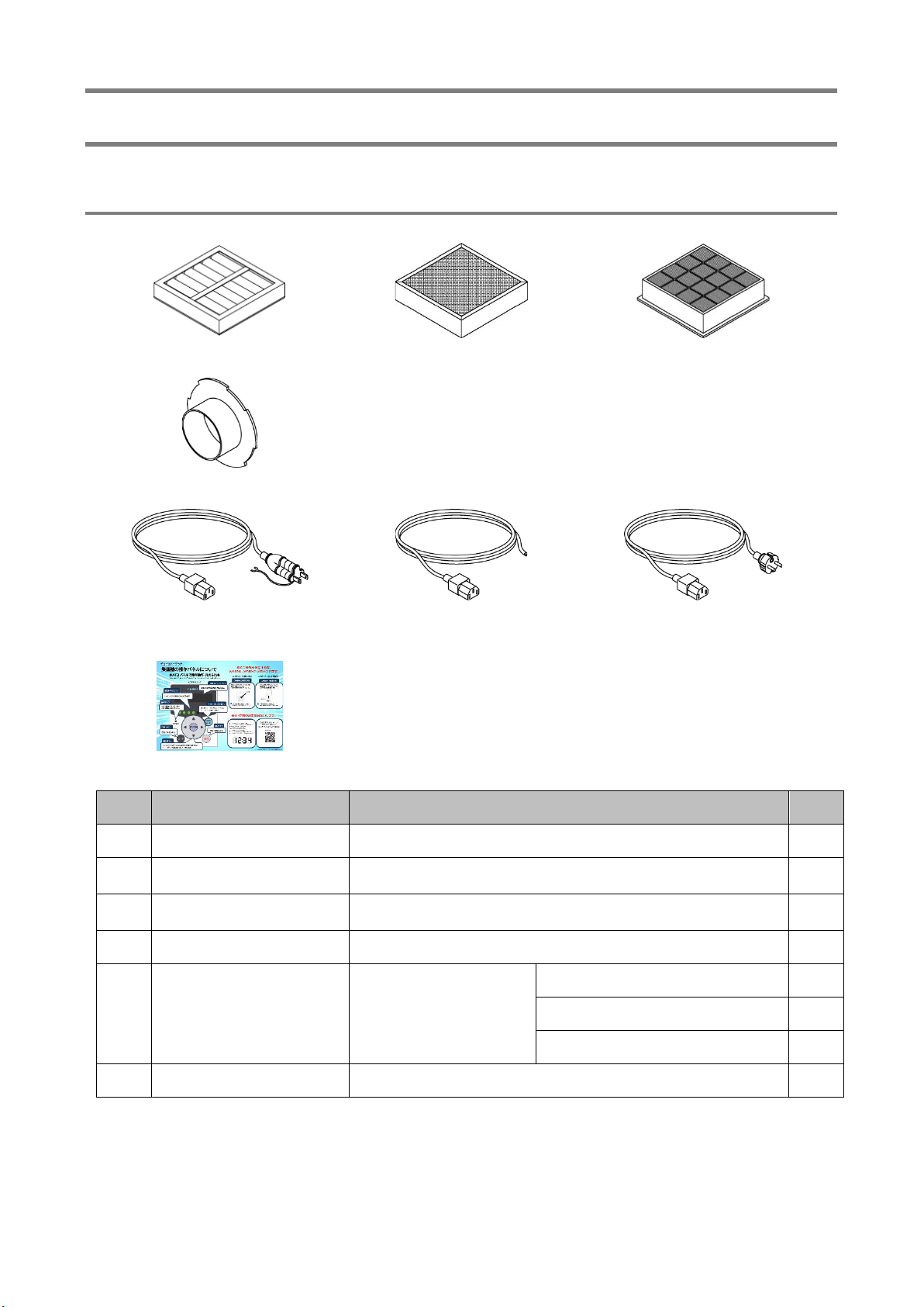
2.1 Accessories
①②③
④
100V version 200V version(-T version)220-230V version(-CE version)
⑤
⑥
No.
Name
Function
Qty.
①
Primary filter
Collects/adsorbs dust.
1
②
Secondary filter
Removes odors by trapping fine particles through collision with
the activated carbon granules.
1
③
Tertiary filter
Prevents activated carbon particles from entering into the
blower.
1
④
Removable flange
Connects a suction duct.
1
⑤
Power cable (3 m)
Connects to the power
outlet.
Shaped differently
depending on power
supply specifications.
100V version*1
1
200 V version (-T version)
1
220/230 V version (-CE version)
1
⑥
Instruction manual
Provides instructions for using the device.
1
*1 Can be used in the area of 100-115V.
Chapter 2 Components Identification
CMN011-006 原本 (Original instructions) 7
English
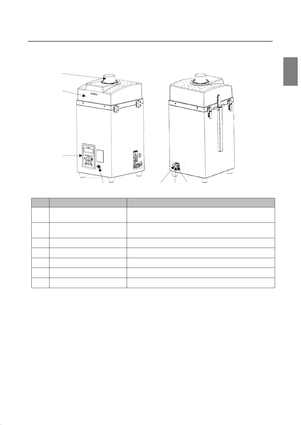
2.2 Device Body
2.2.1 CKU-060AT3-ACC
No.
Name
Function
①
Suction port
(Removable flange)
Connects a suction duct.
②
Suction-side filter case
Contains the primary filter, the secondary filter and
the tertiary filters.
③
AT3 panel (operation panel)
Operates the device.
④
Remote connector
Connects a remote cable (optional).
⑤
Power connector
Connects the power cable.
⑥
Fuse box
Contains a fuse.
⑦
Main power switch
Turns on/off power to the device.
①
②
③
④
⑤
⑥
⑦

Chapter 2 Components Identification
8
2.3 AT3 Panel
No.
Name
Function
①
Organic EL
(OLED) display
Displays the operating status and various settings.
Displays an error or warning number in case of an error or warning.
②
Suction power
level lamps
Green lamps indicate a suction power level (1 to 7).
③
Up/Down arrow
buttons
During stoppage or operation, switches among the content of the display.
“2.4
Display Indications” (page 9)
In MODE SELECT mode, cycles through parameters and changes numeric
data.
“Chapter 4 Configuring Settings (MODE
SELECT Mode)(page14)
④
ERROR lamp
The red lamp lights upon detection of an error that stops device operation.
The red lamp flickers upon detection of an error or warning that continues
device operation.
⑤
Left/Right arrow
buttons
During operation, each pressing of the Left (or Right) arrow button changes
the suction power to the next lower (or higher) level.
During MODE SELECT mode, each pressing of the Left (or Right) arrow
button moves the cursor left (or right) to the next position.
⑥
OFF button
Stops the operation.
During stoppage, holding this button down for three seconds clears the
registered initial pressure.
“3.3
Registering Initial Pressures
“
(page 13)
⑦
ON button
Starts operation.
⑧
ENTER button
During operation, holding this button down for three seconds causes
transition to initial pressure registration.
“3.3
Registering Initial Pressures” (page 13)
During SELECT MODE mode, determines the selected parameter and its
numeric data.
“Chapter 4 Configuring Settings (MODE
SELECT Mode)(page14)
⑨
MODE SELECT
button
During stoppage, transits to the MODE SELECT mode.
“Chapter 4 Configuring Settings (MODE
SELECT Mode)(page14)
During MODE SELECT mode, returns to the previous mode.
During an error/warning, transits to the error history mode or error clear mode.
l
①
②
④
⑥
③
③
⑤
⑦
⑤
⑨
⑧

Chapter 2 Components Identification
CMN011-006 原本 (Original instructions) 9
English
2.4 Display Indications
2.4.1 About Modes
2.4.2 Indications During Stoppage
The Up/Down arrow buttons cycle through indications.
Normal mode
ON button
OFF button
page 14
MODE SELECT button
Page 13
ENTER button
Held down for 3 sec
Main power
switch ON
Page 13
OFF button
Held down for 3 sec
During
stoppage
During
operation
Ver*.** ID.**
Battery ***%
Date: ****/**/**
Time: **:**:**
Program version, RS485 communication ID
Remaining battery level
Date
Time
Clock calibration mode ( Page 15)

Chapter 2 Components Identification
10
2.4.3 Indications During Operation
The Up/Down arrow buttons cycle through indications.
OP **.**kPa
SP **.**kPa
DP **.**kPa
EP **.**kPa
External pressure
Suction pressure
Differential pressure
Exhaust pressure
Blower ***.*°C
Temperature around blower
Motor *****rpm
Motor rotational frequency
Indicates the rotational frequency of the currently running motor.
Runtime ******h
Accumulated run time (resettable)
Indicates run time accumulated since the last resetting.
Accumulated run time reset mode ( Page
16)
Total ******h
Actual run time (not resettable)
Indicates the total run time.

Chapter 3 Operation
CMN011-006 原本 (Original instructions) 11
English
Chapter 3 Operation
3.1 Start-up Preparation
3.1.1 Installation
■Installation location
To ensure operating safety and deliver the full performance of the device, install the device in a location
that meets the following conditions:
Item
Description
Ambient temperature
0° to +40°C
Ambient humidity
80 RH% or lower (without dew condensation)
Ambient conditions
Indoors (not exposed to direct sunlight), free of corrosive/flammable gases,
oil mist, and dust.
■Removing the button battery insulating sheet
While removing the insulation sheet from the button battery, turn on the electricity.
1. Take out the primary filter, secondary filter
and the tertiary filters.
5.1
Replacing Filters
Page17
2. Pull out the insulating sheet off the battery
cover unit.
Note
•The button battery drains when the main power switch is OFF.
1 μA when main power is ON; 40 to 50 μA when main power is OFF
•The battery life (2 years, typical) depends on the usage. Take it as a guide value.
CAUTION
•It will cause a huge consumption of the battery, if the insulation sheet is
removed while the device is turned off.
Battery cover
Insulating
sheet
Chapter 3 Operation
12
3.1.2 Wiring and Piping
■Wiring
WARNING
•Perform wiring firmly, without bending or pulling cables with excessive force.
Fire or electric shock may result.
•Ensure that the power supply conforms to the specifications of the device.
•Be sure to connect the ground wire.
CAUTION
•Avoid multiple connections as they can cause voltage reduction.
At reduced voltage, the device may fail to operate normally, resulting in
failure.
The device is powered by a single-phase supply.
The tolerance of the supply voltage is 10%.
1. Connect the device attachment plug of the power cord to the power connector on the device.
2. Connect the power supply end of the power cord to the power outlet.
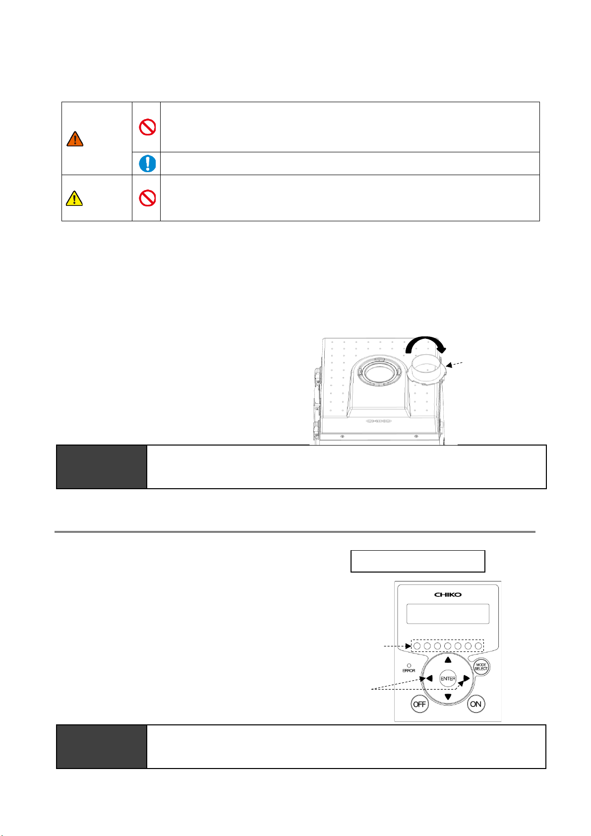
■Piping
1. Turn the removable flange clockwise until it is
secured on the suction port.
2. Connect the suction tube (to be prepared
separately) to the removable flange.
IMPORTANT
•Ensure appropriate piping during operation.
The piping should be as short as practicable, with the piping port diameter not too
small.
3.2 Operation
1. Turn on the main power switch.
The display indicates the program version
and the ID for RS485 communication.
2. Press the ON button on the AT3 panel.
The device starts operation.
3. Check that abnormal noise is not generated
and the suction is appropriate.
4. Set a desired suction power level by
pressing the Left/Right arrow buttons.
The suction power is indicated by the
suction power level lamps (1 to 7).
IMPORTANT
•Leave an interval of three minutes or more between on/off switching.Repeated
on/off switching at intervals of less than three minutes, in particular less than 30
seconds, may cause failure.
Ver*.** ID.**
Left/Right
arrow buttons
Suction power
level lamps
Removable
flange

Chapter 3 Operation
CMN011-006 原本 (Original instructions) 13
English
3.3 Registering Initial Pressures
Air volume reduction due to filter clogging is judged based on a registered initial differential pressure and
indicated as low air volume (WARN4). Register initial pressures through these steps:
1. Perform the wiring and piping of the device.
2. Start the device at a desired suction power level.
3. Press and hold down the ENTER button for three seconds.
The display shows “Initial DP Get Y”, prompting confirmation to register/update initial pressures.
4. To proceed with registration/update, press the ENTER button.
The device starts to acquire initial pressure.
If you do not want update, press the MODE SELECT button to return to normal operation.
5. The device runs through a sequence of suction power levels 1 to 7, to automatically acquire the
differential pressure for each level.
While the device is acquiring initial pressures, the display alternates between the “Initial DP Check”
message and the “suction power level and differential pressure” values.
6. When the registration completes, the display shows the “Initial DP Entry” message and the device
returns to normal operation.
IMPORTANT
•Ensure that the filters are new.
•Update registered initial pressures once again if piping is changed or all filters are
replaced (except for the exhaust filter) after registration of initial pressures.
•If initial pressures are not registered, an “initial pressure unregistered” warning
(WARN6) appears.
•The registered initial pressures can be cleared by holding down the OFF button for
three seconds when the device is in stop state.
●Clearing registered initial pressures
1. Hold down the OFF button for three seconds when the device is in stop state.
The display shows “Initial DP Clr Y”, prompting confirmation to clear registered initial pressures.
2. To clear them, press the ENTER button.
If you do not want to clear them, press the MODE SELECT button to return to normal operation.
3. When the clearing completes, the display shows the “Initial DP Clr” message and the device
returns to the stop state.

Chapter 4 Configuring Settings (MODE SELECT Mode)
14
Chapter 4 Configuring Settings
(MODE SELECT Mode)
4.1 Screen Transitions in MODE SELECT Mode
To move to the MODE SELECT mode, press the MODE SELECT button during stoppage.
The Up/Down arrow buttons cycle through parameters.
4.2 Communication Format Setting Mode
(When Equipped with Communication Function)
This mode sets the below listed items of serial communication format.
The settings are enabled after the main power switch is turned off and back on.
Item
Setting
Default
Communication station number
1 to 25
1
Baud rate
9600 bps, 19200 bps,
38400 bps, 57600 bps,
115200 bps
9600 bps
Bit length and parity
Bit length = 8 bits, with no parity
Bit length = 8 bits, odd parity
Bit length = 8 bits, even parity
Bit length = 9 bits, with no parity
Bit length = 8 bits, with no parity
Stop bit
Stop bit = 1 bit
Stop bit = 2 bits
Stop bit = 1 bit
1. Move to the MODE SELECT mode.
2. Press the Up/Down arrow buttons to move to the communication format setting mode
(“Com Setting”).
3. Press the ENTER button.
The communication station number check screen appears, showing the current settings.
4. Press the Up/ Down arrow buttons to move to the item you want to set.
5. Press the ENTER button.
The setting screen appears.
6. Press the Up/Down arrow buttons to select the desired setting.
[Com Setting]
[Volume Down ST]
[Other Setting]
[Error Data]
Communication format setting mode
(
Page 14)
Air volume-down alert timing setting mode
(
Page 15)
Other setting mode
(
Page 15)
Error history mode
(
Page 16)
Chapter 4 Configuring Settings (MODE SELECT Mode)
CMN011-006 原本 (Original instructions) 15
English
7. Press the ENTER button to determine the setting.
8. To exit this mode, press the MODE SELECT button to return to normal mode.
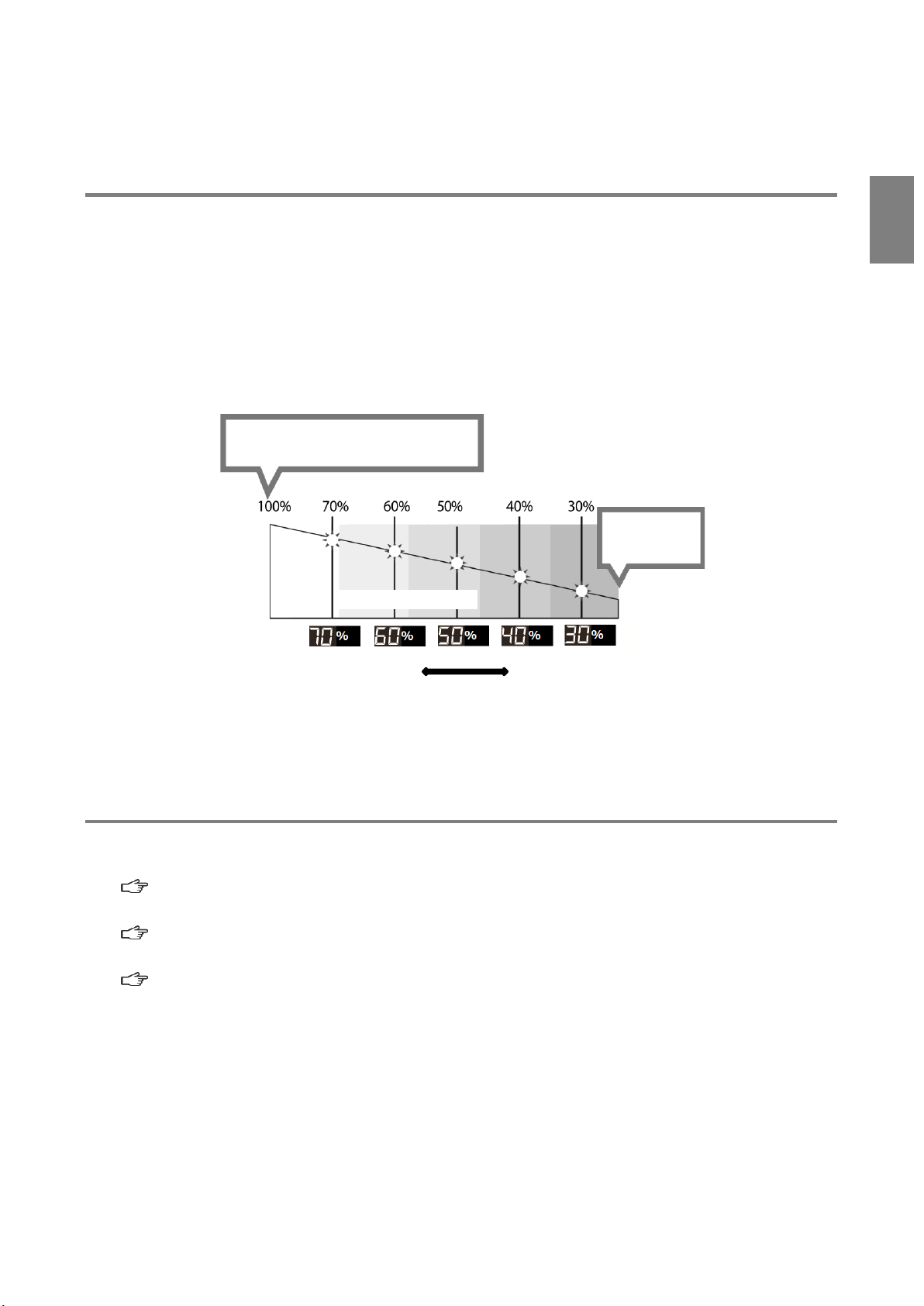
4.3 Air Volume-Down Alert Timing Setting Mode
This mode allows for changing the timing for displaying an air volume-down warning (WARN4) as desired.
1. Move to the MODE SELECT mode.
2. Press the Up/Down arrow buttons to move to the air volume-down alert timing setting mode
(“Volume Down ST”).
3. Press the ENTER button.
The current setting appears.
The default is 50%, displayed as “3: Down to 50%”.
4. Press the Up/Down arrow buttons to select a timing between 30 to 70%.
A lower setting causes the air volume-down alert to occur later, and vice versa.
5. Press the ENTER button to determine the setting.
6. To exit this mode, press the MODE SELECT button to return to normal mode.
4.4 Other Setting Mode
The parameters listed below can be set.
•Date/time setting
“4.4.1
Clock Calibration Mode” (page 15)
•Accumulated run time resetting
“4.4.2
Accumulated Run Time Reset Mode” (page 16)
•Setpoint resetting
4.4.3
Setpoint Reset Mode” (page 16)
4.4.1 Clock Calibration Mode
This mode sets date and time.
1. Move to the MODE SELECT mode.
2. Press the Up/Down arrow buttons to move to the other setting mode (“Other Setting”).
3. Press the ENTER button.
The screen displays “TimeAdjust”.
4. Press the ENTER button.
100% of filter performance is available.
The initially registered value is taken as
100%.
Note: The initial pressure applies when the
suction hose and hood are set in
place.
Differential
pressure lower
Differential
pressure higher
(Default)
Less than 30% of
filter performance
is available.
Filter performance
Setpoint
Lighting occurs earlier.
Lighting occurs later.
Lighting timing can be set to five levels.
To advance the lamp-lighting timing To delay the lamp-lighting timing

Chapter 4 Configuring Settings (MODE SELECT Mode)
16
The date setting screen appears.
5. Press the Up/Down arrow buttons to change the value.
6. Press the ENTER button to determine the value.
Set the value in this order: year, month, and day.
7. After the date is set, the time setting screen appears.
8. Press the Up/Down arrow buttons to change the value.
9. Press the ENTER button to determine the value.
Set the value in this order: hours, minutes, and seconds.
10. To exit this mode, press the MODE SELECT button to return to normal mode.
4.4.2 Accumulated Run Time Reset Mode
This mode resets the accumulated run time (“Runtime”).
1. Move to the MODE SELECT mode.
2. Press the Up/Down arrow buttons to move to the other setting mode (“Other Setting”).
3. Press the ENTER button.
The screen displays “TimeAdjust”.
4. Press the Up/Down arrow buttons to change the display to “[Runtime Reset]”.
5. Press the ENTER button.
The display shows “Reset Runtime Y”, prompting confirmation to reset the accumulated run time.
To reset, press the ENTER button.
6. To exit this mode, press the MODE SELECT button to return to normal mode.
4.4.3 Setpoint Reset Mode
This mode allows for restoring the defaults for communication format, air volume-down alert timing, and
resetting the accumulated run time.
1. Move to the MODE SELECT mode.
2. Press the Up/Down arrow buttons to move to the other setting mode (“Other Setting”).
3. Press the ENTER button.
The screen displays “TimeAdjust”.
4. Press the Up/Down arrow buttons to change the display to “[Setting Reset]”.
5. Press the ENTER button.
The display shows “1:YES”, prompting confirmation to reset setpoints.
To reset, press the ENTER button.
6. The display shows “1:START” for reconfirmation.
7. Press the ENTER button to reset the setpoints and move the device to normal mode.
4.5 Error History Mode
The error history allows for checking four occurrences of errors.
The error history is cleared by turning off the main power switch.
1. Move to the MODE SELECT mode.
2. Press the Up/Down arrow buttons to move to the error history mode (“Error Data”).
3. Press the ENTER button.
The display indicates the number of the most recent error that has occurred and the accumulated
run time at that occurrence.
4. Press the Down arrow button to display the history of four errors in order from the latest.
5. To exit this mode, press the MODE SELECT button to return to normal mode.

Chapter 5 Maintenance and Checkup
CMN011-006 原本 (Original instructions) 17
English
Chapter 5 Maintenance and Checkup
CAUTION
•Before starting maintenance and checkup, be sure to break the electrical
circuit by turning off the power supply and disconnecting the plug from the
power outlet.
5.1 Replacing Filters
If clogging occurs, a “WARN2” warning appears. Replace the primary filter.
If “WARN2” remains displayed after replacing the primary filter, replace the tertiary filter.
5.1.1 Replacing the Primary filter
IMPORTANT
•The filter`s should be replaced in an area large enough to open the suction-side filter
case.
1. Remove the locks (2 places) on the intake
side filter case and open the filter case.
2. Remove the collision plate and replace
the primary filter.
CAUTION
When installing the filter, attach the
packing downward.
Snap locks
Suction-side filter case
Collision plate
Primary filter
Chapter 5 Maintenance and Checkup
18
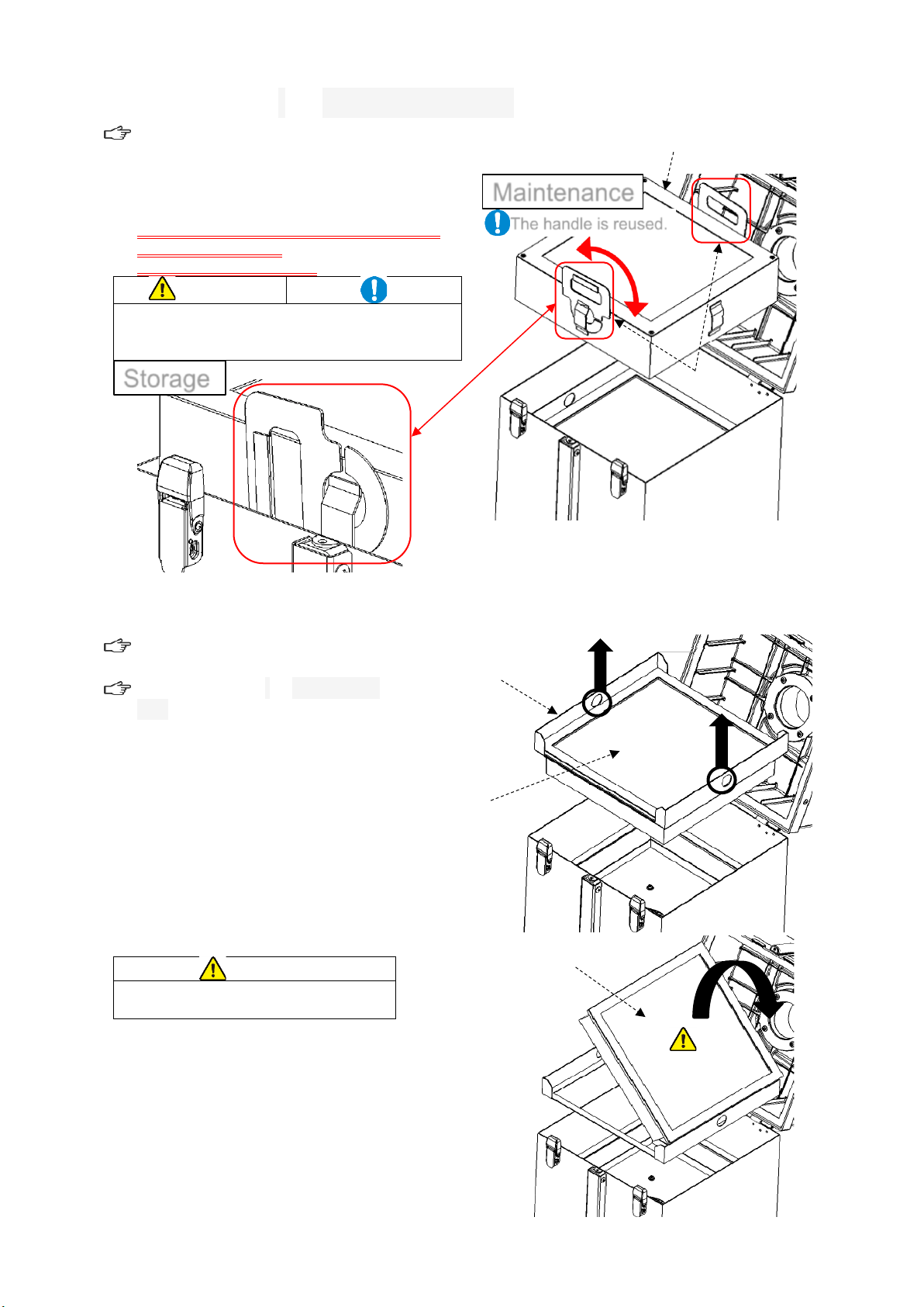
5.1.2 Replacing the secondary filter
5.1.1
「
Replacing the
Primary filter
」
(Page
17)
3. Grasp the handle and replace the activated
carbon box.
* The new activated carbon box does not
come with a handle.
Please reuse the handle.
CAUTION
Please use the handle correctly referring to
the photo.
Incorrect use may damage the dust collector.
5.1.3 Replacing the tertiary filter
5.1.1
「
Replacing the
Primary
filter
」
(Page
17)
5.1.1
「
Replacing the secondary
filter
」
(Page
18)
4. Remove the third filter frame.
* Hook it and take
5. Replace the third filter.
CAUTION
When installing the filter, attach the
packing upward.
Storage
The handle is reused.
Secondary filter
Maintenance
Handle
Third filter
Third filter frame
Third filter
This manual suits for next models
2
Table of contents
Other Showa Denki Dust Collector manuals


