Showline SL BEAM 100 User manual

SL BEAM 100
LED LUMINAIRE

©2014 Philips Group. All rights reserved.
Note: Information contained in this document may not be duplicated in full or in part by any person without prior
written approval of Showline. Its sole purpose is to provide the user with conceptual information on the equipment
mentioned. The use of this document for all other purposes is specifically prohibited.
Document Number: SL BEAM 100 LED Luminaires Users
Version as of: 11th Sep, 2014
SL BEAM 100 LED Luminaire Installation & User’s Manual

1
SL BEAM 100 LED Luminaires Installation & User’s Manual
Sh wline
IMPORTANT INFORMATION
Warnings and Notices
Additional Resources for DMX512
For more information on installing DMX512 control systems, the following publication is available for purchase
from the United States Institute for Theatre Technology (USITT), "Recommended Practice for DMX512: A Guide
for Users and Installers, 2nd edition" (ISBN: 9780955703522). USITT Contact Information:
USITT
315 South Crouse Avenue, Suite 200
Syracuse, NY 13210-1844
Phone: 1.800.938.7488 or 1.315.463.6463
www.usitt.org
Showline Limited Two-Year Warranty
Showline offers a two-year limited warranty of its luminaires against defects in materials or workmanship from the
date of delivery. A copy of Showline two-year limited warranty containing specific terms and conditions can be
obtained by contacting your local Showline office.
When using electrical equipment, basic safety precautions should always be followed including the following:
a.READ AND FOLLOW ALL SAFETY INSTRUCTIONS.
b.Do not use outdoors.
c.Do not mount near gas or electric heaters.
d.Equipment should be mounted in locations and at heights where it will not readily be subjected to
tampering by unauthorized personnel.
e.The use of accessory equipment not recommend ed by the manufacturer may cause an unsafe
condition.
f.Do not use this equipment for other than intended use.
g.Refer service to qualified personnel.
SAVE THESE INSTRUCTIONS.
WARNING : You must have access to a main circuit breaker or other power disconnect device
before installing any wiring. Be sure that power is disconnected by removing fuses or turning the
main circuit breaker off before installation. Installing the device with power on may expose you to
dangerous voltages and damage the device. A qualified electrician must perform this installation.
WARNING : Refer to National Electrical Codes and local codes for cable specifications. Failure to
use proper cable can result in damage to equipment or danger to personnel.
WARNING : This equipment is intended for installation in accordance with the National Electric
Code®and local regulations. It is also intended for installation in indoor applications only. Before
any electrical work is performed, disconnect power at the circuit breaker or remove the fuse to avoid
shock or damage to the control. It is recommended that a qualified electrician perform this
installation.

Installation & User’s Manual SL BEAM 100 LED Luminaires
2TABLE OF CONTENTS Sh wline
TABLE OF CONTENTS
IMPORTANT INFORMATION
TABLE OF CONTENTS
PREFACE
SL BEAM 100 LED LUMINAIRE OVERVIEW
INSTALLATION AND SET UP
OPERATION AND PROGRAMMING
DMX CONTROL
CLEANING AND CARE
TECHNICAL SPECIFICATIONS
SL BEAM 100 LED Luminaire Dimensions 37
......................................................................................................
Showline Offices ................................................................................................................................... 0
Warnings and Notices ............................................................................................................................. 1
Additional Resources for DMX512 ........................................................................................................... 1
Showline Limited Two-Year Warranty....................................................................................................... 1
About this Manual ........................................................................................................................................ 3
Included Items ..............................................................................................................................................3
Accessories ................................................................................................................................................. 3
SL BEAM 100 LED Luminaire Power Input Cables
.................................................................................... 3
SL BEAM 100 LED Luminaire Accessories ............................................................................................... 3
SL BEAM 100 LED Luminaire Components .................................................................................................... 4
Major Luminaire Components .................................................................................................................. 4
LCD Display / Menu System................................................................................................................... 5
Power Requirements...................................................................................................................................... 6
AC Power Operation............................................................................................................................... 6
Connecting Power ......................................................................................................................................... 6
Connecting SL BEAM 100 LED Luminaires to AC Power ............................................................................ 6
Connecting to the DMX512 Network................................................................................................................ 7
Mounting Luminaire...................................................................................................................................... 8
LCD Display and Menu System ..................................................................................................................... 9
LCD Display and Menu System Operation ....................................................................................................... 9
Menu Tree .................................................................................................................................................. 10
Quick Selection Buttons ................................................................................................................................ 11
Edit a Preset Button ............................................................................................................................... 11
Edit a Chase Button
............................................................................................................................... 11
DMX Address Button ............................................................................................................................. 11
Dimming Curve Selection.............................................................................................................................. 12
Master / Slave Operational Mode ................................................................................................................... 13
Simple 8-bit Mode ........................................................................................................................................ 14
Simple 8-bit Group Mode ............................................................................................................................... 15
RGBW 8-bit Mode ........................................................................................................................................15
RGBW 8-bit Group Mode ...............................................................................................................................19
RGBW 16-bit Mode ...................................................................................................................................... 19
HSIC Mode ..................................................................................................................................................24
RGBW 16-bit GroupMode .............................................................................................................................. 23
HSIC GroupMode ......................................................................................................................................... 25
SL BEAM 100 LED Luminaire DMX Timing Channel Details.............................................................................. 26
SL BEAM 100 LED Luminaire RDM Parameter IDs .......................................................................................... 32
Special Cleaning and Care Instructions ............................................................................................................. 36
Front Lens Cleaning ..................................................................................................................................... 36
Service and Maintenance
............................................................................................................................... 36
SL BEAM 100 LED Luminaire Operational Specifications .................................................................................. 37

About this Manual 3
Sh wline
PREFACE
1.About this Manual
The document provides installation and operation instructions for the following products:
S L BEAM 100 LED Luminaire
Please read all instructions before installing or using this product. Retain this manual for future reference. Additional
product information and descriptions may be found on the product specification sheet.
Note: The SL BEAM 100 LED Luminaire is universal voltage 100 to 240 VAC (auto-ranging).
2.Included Items
Each SL BEAM 100 LED Luminaire includes the following items:
S L BEAM 100 LED Luminaire
SL BEAM 100 Quick Start Guide
3.Accessories
SL BEAM 100 LED Luminaire Power Input Cables
SL BEAM 100 LED Luminaire Accessories
Part Number
17-003-0054-00 SL BEAM 100 LED Luminaire AC Power Input Cable ( 1.5 meter)
Part Number Description
Description
60-600-0134-00 Omega Lock for SL BEAM 100 LED Luminaire
SL BEAM 100 LED Luminaires Installation & User’s Manual

4SL BEAM 100 LED LUMINAIRE OVERVIEW
SL BEAM 100 LED LUMINAIRE OVERVIEW
1. SL BEAM 100 LED L u minaire Components
Major Luminaire Components
Figure 1: SL BEAM 100 LED Luminaire Components
Note: *Mounts can be removed and reversed. See "Mounting Luminaire" on page 8 for more information.
Top of Unit
High-Intensity RGBW LED Array
Luminaire Head
DMX512/
AC Input
LCD Display / Menu System
RDM Input
DMX512/
AC Output
RDM Output
Arm
Installation & User’s Manual SL BEAM 100 LED Luminaires
Sh wline

5
LCD Display / Menu System
LCD Display / Menu System
Figure 2: LCD Display & Menu System
Note: For Menu operation and programming details, refer to "LCD Display and Menu System" on page 9.
SL BEAM 100
Home (menu settings)
Edit a Preset Edit a Chase
DMX512 Addressing
Return to Main Screen
LEFT Arrow Button UP Arrow Button
CHECK MARK (Accept) Button
DOWN Arrow Button
RIGHT Arrow Button
LCD Display
NOTE: Menu rotates with orientation of luminaire and
menu buttons are always in the same position (with
rotation of menu)
To rotate menu 180 degrees from current orientation,
press and hold the two center buttons for 2 seconds.
SL BEAM 100 LED Luminaires Installation & User’s Manual
Sh wline

6INSTALLATION AND SET UP
INSTALLATION AND SET UP
1.Power Requirements
The SL BEAM 100 LED Luminaire operates on AC input voltages from 100 to 240 VAC.
WARNING! This unit does not contain an ON/OFF switch. Always disconnect power input cable to completely
remove power from unit when not in use.
AC Power Operation
When connected to an AC source, the unit operates on 100 to 240 volts AC (+/- 10%, auto-ranging). The luminaire
contains an auto-ranging power supply. Each luminaire can draw up to 150 Watts.
WARNING! Maximum amount of units that may be daisy-chained is (A) 11 units 100 ~ 120VAC (15 Amps) or (B)20
units 230 ~ 240VAC (15 Amps).
Note: For wiring of AC input connector, refer to "Connecting SL BEAM 100 LED Luminaires to AC Power"
on page 6.
2.Connecting Power
Units can be powered in one of two ways:
Direct connection to a AC power sour c e using an AC input cable.
Connection from the AC output of another SL BEAM 100 L ED Luminaire. When using this method, it is
very important not to connect any other type of equipment device.
WARNING! Only connect other SL BEAM 100 LED Luminaires to the AC Output (Thru) connector of a SL
BEAM 100 L ED Luminaire.
Connecting SL BEAM 100 LED Luminaires to AC Power
Figure 3 on page 7 describes how to connect power to your SL B EAM 100 LED Luminaire. Field wiring of the
SL BEAM 100 LED Luminaire is straight forward. A total of 3 wires/conductors is supplied from the unit. The
following wiring scheme is used:
Table 1: SL BEAM 100 LED Luminaire Voltage (VAC) vs. Current*
Voltage (AC)Total Current (A)Voltage (AC)Total Current (A)
Installation & User’s Manual SL BEAM 100 LED Luminaires
Sh wline

Connecting to the DMX512 Network 7
Figure 3: SL BEAM 100 LED Luminaire AC Input & Output Connections
CAUTION: In the event the AC input cable of this luminaire is damaged, it must be replaced, by the user, with an
approved cable through an Authorized Showline Dealer or Service Center.
3.Connecting to the DMX512 Network
Basic DMX512 installation consists of connecting multiple SL BEAM 100 LED Luminaires together (up to 32
luminaires) in "daisy-chain" fashion. A cable runs from the control console (or DMX512 control source) to the DMX
connector on the first SL BEAM 100 LED Luminaire. Another cable runs from the other DMX connector on
the first unit to a DMX connector on the next SL BEAM 100 LED Luminaire (or DMX512 device to
be controlled).
Figure 4: SL BEAM 100 LED Luminaire DMX512 Input / Output Connections
AC Input
AC Output
Neutral Main /
Ground / Earth
Line
AC Connector
(on side of unit)
AC Input Connector (on Unit)
Neutral
Main /
Ground / Earth
Line
AC Connector
(on side of unit)
AC Output Connector (on Unit)
DMX512 / RDM Input
DMX512 / RDM Output
SL BEAM 100 LED Luminaires Installation & User’s Manual
Sh wline

Mounting Luminaire
Note: For more information on DMX512 networking and systems, refer to "Additional Resources for DMX512" on
page 1. For SL BEAM 100 LED Luminaire DMX Mapping, refer to "DMX CONTROL" on page 14.
Figure 5: SL BEAM 100 LED Luminaire - DMX512 Connections
4. Mounting Luminaire
The SL BEAM 100 LED Luminaire is provided with two mounts and safety cable anchor points.
The two mounts are easily removed and reversed as required. These mounts are designed to accept a variety of
mounting hooks, clamps, etc. for hanging applications. Refer to Figure 6 for additional information. Note, the bottom
Simply attach hook, clamp, etc. to the SL BEAM 100 LED Luminaire mount assembly in the M13 hole.
Note: Mounting hooks, clamps, etc. are sold separately or by others. For available mounting accessories refer to
"Accessories" on page 3.
Figure 6: Mounting Luminaire - Hanging Applications
DMX512
DMX512 (out from first
to second luminaire)
DMX512 (out to the next
luminaire or DMX512
controlled device)
SL BEAM 100 SL BEAM 100
DMX512 Connections
Note: Remaining pins on each connector are not used.
DMX512 Signal XLR Pin
Common (Drain)1
DMX512 - 2
DMX512 + 3
(from console or
control device)
LED Luminaires LED Luminaires
of the luminaire must be free and clear of any objects (i.e.,scenery) to allow for proper airflow
SAFETY CABLE: Is sold
separately and recommended
for all hanging installation and
may be required by national
Hook / Clamp
and local codes. Use enclosure
handles for safety cable anchor
points for this fixture.
Installation & User’s Manual SL BEAM 100 LED Luminaires
Sh wline

LCD Display and Menu System 9
OPERATION AND PROGRAMMING
1. LCD Display and Menu System
The SL BEAM 100 LED Luminaire’s LCD Display and Menu System provides local control for accessing the
following fixture’s settings:
Presets (Standard and User Defined)
Color Filters
Effects (Chases - preloaded and user defined)
Strobe / Timing
Settings
Lock Fixture (to prevent changes)
Password
Status
Setting the DMX512 Address
Note: If there are multiple luminaires in a system, changes would need to be made at each LCD Menu as desired.
Upon power up, the LCD will display the main screen showing the product type/name. If DMX is enabled,
the programmed address will appear after power up.
Figure 7: LCD Display and Menu System
2. LCD Display and Menu System Operation
The LCD Display Menu system consists of several categories. Use the Menu Buttons to access and make changes to
the menu items. When the desired menu item is reached, press the desired Menu Button to display the menu options
and to navigate and configure the menu options as required.
To navigate and access menu settings/selections:
Step 1.Make sure unit is powered and turned on.
Step 2.Press the desired button (as shown in F i g ure 7) to access menu categories.
Step 3.Use UP | DOWN | LEFT | RIGHT arrow buttons to n a vigate through the various options and settings.
Step 4.Make changes as desired.
Step 5.Press CHECK MARK (OK) button to accept changes.
SL BEAM 100
Home (menu settings)
Edit a Preset Edit a Chase
DMX512 Addressing
Return to Main Screen
LEFT Arrow Button UP Arrow Button
OK (Check Mark) Button
DOWN Arrow Button
RIGHT Arrow Button
LCD Display
NOTE: Menu rotates with orientation
of Luminaire and menu buttons are
always in the same position (with
rotation of menu)
To rotate menu 180 degrees from
current orientation, press and hold the
two center buttons for 2 seconds.
SL BEAM 100 LED Luminaires Installation & User’s Manual
Sh wline

10
SL BEAM 100 LED Luminaire Menu Tree
SL BEAM 100 LED Luminaire Menu Tree
Figure 8: SL BEAM 100 LED Luminaire Menu Tree
Installation & User’s Manual SL BEAM 100 LED Luminaires
Sh wline

11
3. Quick Selection Buttons
Quick Selection Buttons
When in Manual Mode, the SL BEAM 100 LED Luminaire’s features can be accessed via the on-board LCD
menu system or via three quick select buttons:
Edit a Preset Button
Edit a Chase Button
DMX Address Button
Edit a Preset Button
To edit and save a preset:
Step 1.Press Edit a Preset button. Current preset will be shown.
Step 2.Use LEFT and RIGHT arrow buttons to scroll through all presets.
Step 3.Once at desired preset, use U P and DOWN arrows to access
(highlight) preset parameters. Once in desired parameter, use LEFT
and RIGHT arrow buttons to adjust parameter value as desired.
Step 4.Once all values are adjusted as des i r e d, press OK (Check Mark) button.
Step 5.Save preset menu option will appear. Use LEFT a n d RIGHT arrow button to select preset number.
Step 6.If saving preset, press OK ( C heck Mark) button. Confirm choice.
Step 7.Preset is now saved.
Edit a Chase Button
To edit and save a chase:
Step 1.Press Edit a Chase butto n. C u rrent chase will be shown.
Step 2.Use LEFT and RIGHT arrow buttons to scroll through all chases
(Built In and User Chases).
Note: For Built In Chases, only the Speed, the Master Intensity and Fade parameters
may be changed and saved. For User Chases, Chase Number, Total Steps, Speed,
and Fade Parameters may be changed and saved.
Step 3.Once at desired chase, use UP and DOWN arrows to access (highlight) chase parameters. Once in desired
parameter, use LEFT and RIGHT arrow buttons to adjust parameter value as desired.
Step 4.Once all values are adjusted as des i r e d, press OK (Check Mark) button.
Step 5.Save chase menu option will appear. Use LEFT and RIGHT arrow buttons to select chase number.
Step 6.If saving chase, press OK (Ch e c k Mark) button. Confirm choice.
Step 7.Chase is now saved.
DMX Address Button
To edit and save a DMX address:
Step 1.Press DMX Address button. Cur r e nt DMX Address will be shown.
Step 2.Press OK (Check Mark) button to highlight a digit in the DMX
address.
Step 3.Use LEFT and RIGHT arrow buttons to scroll through all digits.
Step 4.Once at desired digit, use UP and DOWN arrows to change
highlighted digit. Once digit is set, use LEFT and RIGHT arrow buttons to set other digits in DMX address.
Step 5.Once all digits are set in DMX add r e ss, press OK (Check Mark) button.
Step 6.DMX will display and is saved.
Edit a Preset
R
M
G
Preset: 2 All Pixel
B
W
12
0
43
75
75
Edit a Preset
Edit a chase
User Chase: 6
100
3
1 s
%
100
Edit User Chase
Edit a Chase
Address
267
DMX Address
%%
%
%
%
%
Effect Engine
Fade
Total Steps
Master Intensity
Speed
%
SL BEAM 100 LED Luminaires Installation & User’s Manual
Sh wline
12 Dimming Curve Selection
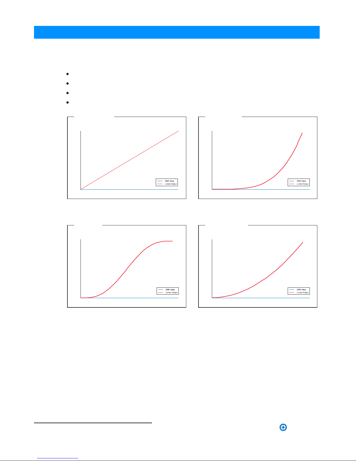
4.Dimming Curve Selection
Through the menu, you are able to select one of four dimming curves:
Linear Curve
S_Curve
Square Curve
Figure 9: SL BEAM 100 LED Luminaire Dimmer Curves
*PL Curve follows the dimming curve of Philips Selecon PL
series LED luminaries.
DMX Value
Lumen Output
0
Linear Curve
DMX Value
Lumen Output
0
S_Curve
DMX Value
Lumen Output
0
Square Curve
DMX Value
Lumen Output
0
PL_Curve *
PL_Curve
Installation & User’s Manual SL BEAM 100 LED Luminaires
Sh wline

13
5.Master / Slave Operational Mode
Master / Slave Operational Mode
The Master / Slave Operational Mode allows one SL BEAM 100 LED Luminaire to act as the "Master" unit
and all other connected units are controlled by this unit. When a unit is set to "Slave" mode, it will only listen to and
follow any commands sent from a "Master" unit. Only one "Master" unit is allowed in this type of operation.
To setup a master / slave network:
Step 1.Set the first device in the DMX512 chain to M a ster Mode through the unit’s menu system.
Step 2.Set all other connected units to S l a ve Mode
.
Step 3.The master unit can be controlled via DMX512, R D M or through standalone operation (self-contained
network utilizing on-board effects). The slave units will mimic the master unit’s operation in all cases.
Note: For more information on DMX512 networking and systems, refer to "Additional Resources for DMX512" on
page 1"DMX CONTROL" on page 14. For SL BEAM 100 LED Luminaire DMX Mapping, refer to .
Figure 10: SL BEAM 100 LED Luminaire - Master / Slave Configuration
DMX512
DMX512 (out from first
to second luminaire)
DMX512 (out to the next
luminaire or DMX512
controlled device)
SL BEAM 100 SL BEAM 100
(from console or
control device)
LED Luminaires LED Luminaires
SL BEAM 100 LED Luminaires Installation & User’s Manual
Sh wline

14
DMX CONTROL
DMX CONTROL
This section contains information for operating the luminaire using DMX control in Simple 8-bit, RGBW 8-bit,
RGBW 16-bit, and HSIC modes. For Menu options and detailed information, see "LCD Display and Menu System"
.
Note: These tables assume a DMX start address of 1. When a different starting address is used, this address becomes
channel 1 function and other functions follow in sequence.
1.Simple 8-bit Mode
Table 2 provides DMX channel mapping of all DMX512 control values when the SL BEAM 100 LED
Luminaire is in Simple 8-bit mode (as set by the luminaire’s menu system).
Table 2: SL BEAM 100 LED Luminaire DMX Channel Mapping (Simple 8-bit Mode)
1 Pan - High Byte
2 Tilt - High Byte
3 Master Intensity 8 bit control for Intensity of LED settings.
4 Strobe 0
0
Controls strobe operations as follows . . .
Open = DMX 0 - 2
Closed = DMX 3 - 5
Slow Rand = DMX 6 - 7
Med Rand = DMX 8 - 10
Fast Rand = DMX 11 - 12
Strobe Range = DMX 13 - 127 (fastest)
Pulse + Slow Rand = DMX 128 - 129
Pulse + Med Rand = DMX 130 - 131
Pulse + Fast Rand = DMX 132 - 133
Pulse + Range = DMX 134 - 191
Pulse - Slow Rand = DMX 192 - 193
Pulse - Med Rand = DMX 194 - 195
Pulse - Fast Rand = DMX 196 - 197
Pulse - Range = DMX 198 - 255
5 Zoom 0Variable control of zoom from 12 - 45
6 Control 0
7 Red1-3 08 bit control of Red LEDs from 0 to full.
8 Green1-3 08 bit control of Green LEDs from 0 to full.
9 Blue1-3 08 bit control of Blue LEDs from 0 to full.
10 White1-3 08 bit control of White LEDs from 0 to full.
Page1of1
Functions of the SL Series products. Set control channel value
to desired action,Hold value for at least 5 seconds ,then turn to 0.
Set control channel value to 0 without any scaling.
Default Setting on Console = DMX 0-4
DIM Response _Normal = DMX 5 - 9
DIM Response_Incandescent = DMX 10 - 14
Dimming Curve_linear = DMX 30 - 34
Dimming Curve_Square = DMX 35- 39
Dimming Curve_S-Curve = DMX 40 - 44
Dimming Curve_PL-Curve = DMX 45 - 49
Calibration_OFF = DMX 70 - 74
Calibration_ON = DMX 75 - 79
Fan_Auto = DMX 80 - 84
Fan_Off = DMX 85 - 89
Reserves( Future use) = DMX 90 - 250
8-bit control of Pan
8-bit control of Tilt
128
128
0 - 100%
0 - 100%
0 - 100%
0 - 100%
0 - 100%
0 - 100%
0 - 100%
0 - 100%
0 - 100%
0 - 100%
0 - 255
0 - 255
0 - 255
0 - 255
0 - 255
0 - 255
0 - 255
0 - 255
0 - 255
0 - 255
on page 9
Installation & User’s Manual SL BEAM 100 LED Luminaires
Sh wline
DMX Parameter Range DMX Range % Defaults Description

15
3.RGBW 8-bit Mode
Table 4 provides DMX channel mapping of all DMX512 control values when the SL BEAM 100 LED
Luminaire is in RGBW 8-bit mode (as set by the luminaire’s menu system).
Table 4: SL BEAM 100 LED Luminaire DMX Channel Mapping (RGBW 8-bit Mode)
2.Simple 8-bit Group Mode
Simple 8-bit Group Mode
Table 3 provides DMX channel mapping of all DMX512 control values when the SL BEAM 100 LED
Luminaire is in Simpe 8-bit Group mode (as set by the luminaire’s menu system).
Table 3: SL BEAM 100 LED Luminaire DMX Channel Mapping (Simple 8-bit Group Mode)
RGBW 16 BIT MODE
DMX Parameter Range DMX Range % Defaults Description
SL BEAM 100 LED Luminaires Installation & User’s Manual
Sh wline

16 RGBW 8-bit Mode
Table 4: SL BEAM 100 LED Luminaire DMX Channel Mapping (RGBW 8-bit Mode)
Installation & User’s Manual SL BEAM 100 LED Luminaires
Sh wline

RGBW 8-bit Mode 17
Table 4: SL BEAM 100 LED Luminaire DMX Channel Mapping (RGBW 8-bit Mode)
SL BEAM 100 LED Luminaires Installation & User’s Manual
Sh wline

18 RGBW 8-bit Mode
Table 4: SL BEAM 100 LED Luminaire DMX Channel Mapping (RGBW 8-bit Mode)
Installation & User’s Manual SL BEAM 100 LED Luminaires
Sh wline
Table of contents
Popular Light Fixture manuals by other brands

Schmitz-Wila
Schmitz-Wila EM4107001 installation instructions

Inspire
Inspire Skarla WE29211H90 instruction manual

Lindam
Lindam MK0089 manual

Gainsborough
Gainsborough L105 quick start guide

Triarch
Triarch Indoor Lighting 29585-GOLD Assembly instructions

RSA Lighting
RSA Lighting Combolight LV Series LV840MHSQ Specifications

Lightolier
Lightolier Lytecaster 1001FR Series Installation

Venue Lighting Effects
Venue Lighting Effects Dual Scanner user manual

Triarch
Triarch 25931 Installation and wiring instructions

Wildfire
Wildfire Long-Throw WF-402FF Operation manual

Nemo
Nemo Studio LUX S Mounting instructions

Lightolier
Lightolier Coffaire II CFA2GPF217 manual


