SHYFT STROBESRUS SRUS-VL22 Manual
INSTALL MANUAL
SRUS-VL22 LED VISOR LIGHT
A SHYFT Group Brand
Please be sure to check that your cigarette plug outlet is properly fused. Testing the light before this fuse is properly
installed will void the warranty on the light.
Our visor light is designed to be mounted on the inside of your vehicle. It is not intended for exterior applications.
It is the sole responsibility of the owner to ensure the warning light is secure. Check your light every time you enter
the vehicle to ensure that it is mounted securely.
MOUNTING
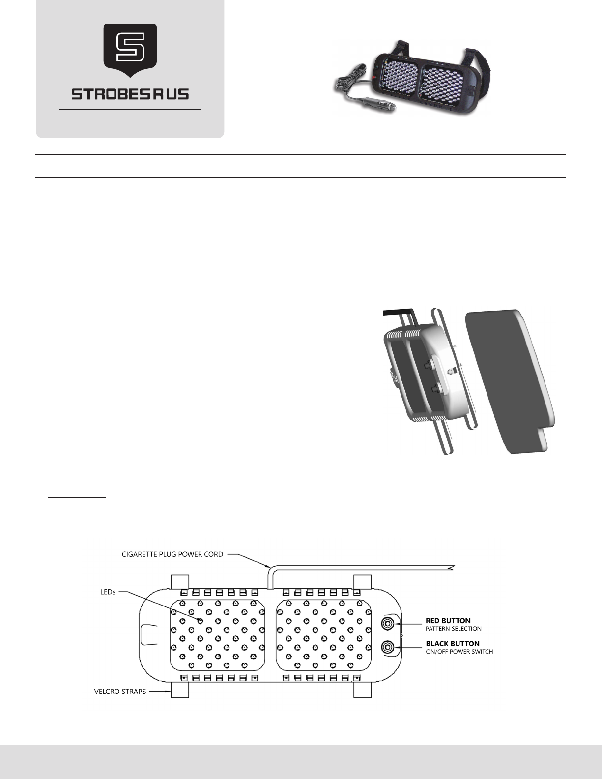
The lighter plug and the velcro straps allow quick and easy installation.
1. Place the vehicle’s sun visor in the “down” position and use the two
Velcro straps to attach the light to the visor, with the cigarette plug
cord exiting the top of the light.
2. The VL22 must be mounted with the power cord exiting the top of
the light or the tilt-switch will not function properly.
3. With the at side of the light mounted against the visor and the
LEDs pointing towards the windshield, adjust the straps so that the
light may be slid over the end of the visor. Once in place, tighten the
straps to the desired tension.
4. Route the wire across the top of the visor and down to your cigarette
plug outlet.
SRUS-VL22 Install manual Page 1
IMPORTANT:
Once the light is secured, route your cord such that it does not interfere with the vision of the driver or the operation
of the steering wheel, gear shifter, and/or any airbags.

OPERATION
ON/OFF BUTTON:
There are two push-button switches located to the right on the face of this visor light . The bottom button is BLACK and
switches the unit ON and OFF. When the unit is switched ON, the red LED in-between the two buttons, will illuminate
signifying that the light is in Standby Mode. While in Standby Mode, the light will remain o when the visor is in the up
position. The light will activate when the visor is ipped down. When the RED LED is not lit, the light is OFF and will not
ash in any position.
PATTERN SELECT BUTTON:
The RED push-button switch is the Pattern Select button. Each time this button is pressed, the light will cycle to the next
pattern. This light is designed with 24 patterns. The light will cycle back to the rst pattern after pattern #24.
Note: The pattern select button must be depressed for more than one second to advance to the next ash pattern.
TILT OVERRIDE:
Normally the visor light will remain o when the visor is in the up position and it will activate when the visor is ipped
down. If you would like to de-activate this feature so that the light is controlled only by the On/O button, regardless of
the visor position, hold the RED Pattern Select button until the light ashes 7 times (approximately 21 seconds). Repeat
this to turn the Tilt feature back on.
TECHNICAL DATA
• Voltage: 9 - 16 VDC
• Nominal Voltage: 12 VDC
• Current Draw: 1A avg, 2.8A Peak @12.8 VDC
• Dimensions: 11 1/8” W x 4” H x 7/8” D
• Connection: 11.5 ft long cig plug cord
• Mounting: Velcro straps
• Material: Polycarbonate
• Approvals: SAE J595 Class 1 (A/W, A/G Class 3)
• 24 Tilt-activated ash patterns
• Reverse polarity protection
• Vibration resistant LED technology
• Available colors: R/B, R/R, B/B, R/W, A/W, A/G
• Weight: less than 1.00 lb
SRUS-VL22 Install manual Page 2
Please read all the following instructions before installing your LED visor light.
Failure to install or use this product according to manufacturer’s recommendations may result in property damage or serious injury.
• Proper installation of this product requires the installer to have a good understanding of automotive electronics.
• This product contains high-intensity LEDs. Do not stare directly into these lights. Could result in blindness and/or eye damage.
• Do not install this product or route any wires in the deployment area of the vehicle’s airbag zone. Equipment mounted or
located in the airbag deployment zone will damage or reduce the eectiveness of the airbag or become a projectile that could
cause serious personal injuries. Refer to the vehicle owner manual for the airbag deployment zone.
• If mounting this product requires drilling holes, the installer must be sure that no vehicle components or other vital parts could
be damaged by the drilling process. For example: The vehicle’s OEM wiring harness.
• Inspect and operate this product regularly to conrm its proper operation and mounting condition.
• This light has a 5 year warranty. If the product is not installed per the installation guidelines, the 5 year warranty will be void.
FAILURE TO FOLLOW THESE SAFETY PRECAUTIONS COULD RESULT IN DAMAGE TO THE PRODUCT OR VEHICLE
AND/OR SERIOUS INJURY TO YOU AND YOUR PASSENGERS!
SRUS-VL22 Install manual Page 3
PATTERN PROGRAMMING
The RED push-button switch is the Pattern Select button. Each time this button is pressed, the light will cycle to the next
pattern. This light is designed with 24 patterns. The light will cycle back to the rst pattern after pattern #24.
STEADY BURN PROGRAMMING
While the light is running, hold the Pattern Select button until the light blinks 6 times (18 seconds), then release it.
• For Lights set to an alternating ash pattern (1-12), one half will become steady, while the other side ashes.
- To change the pattern on the ashing side: Press and release the Pattern Select button
- To ip-op the steady side and the ashing sides: Hold the Pattern Select button until the light ashes 5 times
(15 seconds) and then release it.
• For Lights set to a simultaneous ash pattern (13-24), the entire light should illuminate steady burn.
EXIT STEADY BURN PATTERN
• Light set to an alternating ash pattern (1-12): Hold the Pattern Select button until the light ashes 6 times
(18 seconds) and then release it.
• Light set to a simultaneous ash pattern (13.-24): Press and release the Pattern Select button.
Flash pattern Pattern Description Shortcuts
Hold the Pattern Select
button for indicated time
Alternating
(Phase 1)
Simultaneous
(Phase 2)
1 13 Flicker * Jump to:
Pattern 1
hold 3 seconds or 1 ash
Pattern 13
hold 9 seconds or 3 ashes
2 14 Fast Doubleash *
3 15 Tripleash *
4 16 PSU Flicker (default)
517 PSU Random
6 18 Quadash * Jump to:
Pattern 6
hold 6 seconds or 2 ash
Pattern 18
hold 12 seconds or 4 ashes
719 Quadash w/Post-Pop *
8 20 Singleash *
9 21 Doubleash *
10 22 Variable AKA Delta-Omega
11 23 Post Pop *
12 24 Random
#Steady hold 18 seconds or 6 ashes
* - SAE J595 approved patterns


