SI Solo 2 User manual

Solo / Pro 2
Installation Instructions
24v (Low Voltage) Motors
Screen Innovations
9715-B Burnet Rd, Suite 400 Austin, TX 78758
512.832.6939
www.screeninnovations.com
v. 1.2 19 Sept 2019

Thank you for purchasing an SI product. If you have
any questions or need any assistance with your
Solo Pro, we would love to help you.
Technical Support: 512.832.6939
Hours of Support: 7:30am - 5pm CST
screeninnovations.com
CONTENTS
Initial Consideration ................................................... Pg 1
Parts in the Box - 24v RTS ........................................ Pg 2
Parts in the Box - 24v RS485 .....................................Pg 3
Spacer Blocks and Leveling Shims ......................... Pg 4
Pre-wire 24v RTS ......................................................... Pg 5
Pre-wire 24v RS485 .................................................... Pg 6
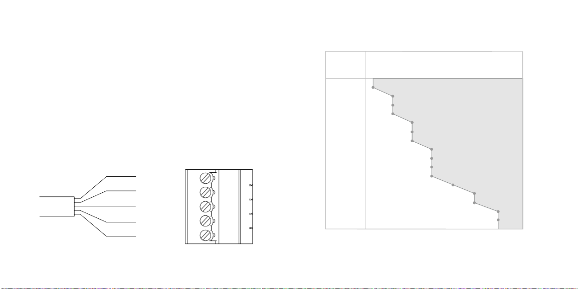
Power Wire distance chart ........................................ Pg 7
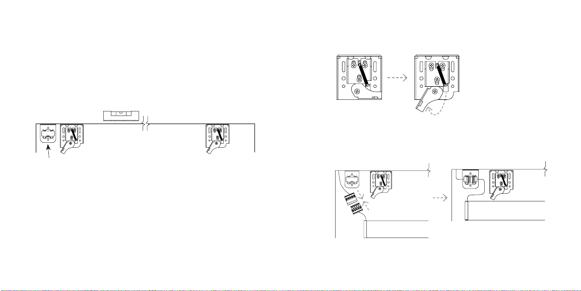
Installation .................................................................... Pg 8 - 16
24v RTS
Running ........................................................................ Pg 17
Programming ...............................................................Pg 18 - 19
Pairing another RF Remote .......................................Pg 20
24v RS485
Programming with SIFI .............................................Pg 21 - 24
Programming with Limit Setting Tool.....................Pg 25 - 28
Programming with USB Programming cable........Pg 29 - 30
Control with 3rd Party - via Serial.............................Pg 31
Control with 3rd Party - via SIFI................................Pg 32 - 33
Control with 3rd Party - via DCT................................Pg 34 - 35
Solo Pro 2Solo 2
Please use these QR Codes to access the updated
installation instructions and video tutorials.

1
CONTENTS (cont.)
Mounting Accessories ............................................ Pg 36
Motor Accessories 24v RTS ................................... Pg 37
Motor Accessories 24v RS485............................... Pg 38
Storage and Transport ........................................... Pg 39 - 40
Care and Maintenance ........................................... Pg 41 - 43
Troubleshooting ........................................................ Pg 44 - 46
Warranty ..................................................................... Pg 47 - 48
INITIAL CONSIDERATIONS
Thank you for your purchase of Solo/Pro 2. The
screen is mountable outdoors, but is not waterproof.
It has not been designed to be run or left in the rain or
condensing humidity. Also avoid water spray, splash
and extreme heat or cold. Protect your Solo/Pro 2. and
you can expect years of quality use.
For a quick install it is recommended you run
appropriate wire to the installation location before
installing the screen. See the Pre-Wire sections for your
particular control method for details.
Initial Considerations

32
24v RTS
PWR Solo/Pro 2 screen
RF Remote
Low Voltage Power
Supply
Parts in the box
24v RTS - Parts in the Box
(2) Ceiling/Wall
Locking brackets
Terminal block
receptacle and bracket
(6) Wood
fasteners
(6) Leveling Shims
(6) Wood
fasteners
Low Voltage
Power Supply
24v RS485
Additional accessories required for RS485 control (pg 38)
Parts in the box
Solo/Pro 2 screen
RS485PWR
24v RS485 - Parts in the Box
(2) Ceiling/Wall
Locking brackets USB Programming Kit
Terminal block
receptacle and bracket
(6) Leveling
Shims

54
Spacer Blocks & Leveling Shims
SPACER BLOCKS & LEVELING
SHIMS
Spacer Blocks are used
to clear an obstruction on
the wall. Connect spacer
block to each wall bracket
before installation.
Leveling Shims are used
if the ceiling or other
mounting surface is out
of level or plumb. Connect
to ceiling brackets before
installation.
PRE-WIRE - 24v RTS
1. Run 2 conductor wires to the left side of screen
cassette installation location (refer to pg. 11). Follow
the power wire distance chart (refer to pg. 7) to
ensure use of the correct wire gauge.
2. Terminate the wires with the provided terminal block
as shown below.
+ 24 VDC
- 24 VDC
V+
V-
+
-
G
Not
used
Pre-Wire - 24v RTS

76
+ 24 VDC
- 24 VDC
Data +
Data -
Data ground
V+
V-
+
-
G
PRE-WIRE - 24v RS485
1. Run minimum 5 conductor wire to the left side of
screen cassette installation location (refer to pg. 11).
To be sure you have the correct wire, order directly
from SI (Part # - Non-Plenum - 800269/ 9020126
and Plenum rated - 9020127). If you are using third
party wire, follow the power wire distance chart
(refer to pg. 7) to ensure use of the correct wire
gauge for the 24 VDC wires.
2. Terminate the wires with the provided terminal
Pre-Wire - 24v RS485
Do not use any combination above the line.
over 100
100
90
80
70
60
50
45
40
35
30
25
20
15
10
5
Distance
(ft.) 12 14 16 18 20 22 24
Standard Cu Wire Guage (min.)
POWER WIRE DISTANCE CHART
Power Wire Distance Chart

98
Proper mounting preparation will ensure a great
installation. Mounting brackets must be level to each
other, as well as plumb. They must be screwed into
structural members of some kind, such as ceiling joists
or wall studs. You may use the wood screws provided,
or other anchors (not provided) capable of carrying the
load, that are suitable to the substrate.
DO NOT MOUNT TO HOLLOW SHEET ROCK.
1. The drop is adjustable in the field between 0'' and
the MAX DROP (12'', 24'', or 36'', 2'' for short throw)
ordered for your screen. Use the drawing (refer to
pg. 9) to pick a bracket height that will allow you to
extend your screen to achieve the desired vertical
position of your viewing area.
INSTALLATION
Solo/Pro 2 - Installation Solo/Pro 2 - Installation
13
4"
View Height
Drop
3.43”
(87mm)
2.02”
(51mm)
4.88”
(124mm)
3.43”
(87mm)
2.01”
(51mm)
3.78”
(96mm)
2.87”
(73mm)
2.85”
(72mm)
1.61”
(41mm)
Bracket
size
Small Medium Large

1110
2. Determine the desired horizontal viewing position
centerline of the projected viewing area.
3. The Solo/Pro 2 screen must be installed with the
brackets no more than 4 inches from each end of
the cassette. Measure the overall length of the
cassette to determine the min and max horizontal
spacing of the mounts. Mark the location of the
brackets over a stud or ceiling joist and within an
appropriate distance from the ends. If the location
of the stud or ceiling joist does not allow the center
of the screen to match the projector lens' center,
another board or plate will have to be installed on
the wall or ceiling to take the mount fasteners.
Solo/Pro 2 - Installation Solo/Pro 2 - Installation
wire
exits back
corner
of the
cassette
Cassette Length
View Width
Brackets secured to Wall or
Ceiling Structural Supports
Screen Centerline Structural Supports
1" Min to 4" Max
pull wire
through the
hole in gray
zone

1312
4. Secure the brackets to the wall or ceiling structural
supports using appropriate fasteners. Make sure the
brackets are along the same level line. Install the
terminal block bracket next to the left bracket. This
bracket is used to hold the power and/or controls
terminal block easily out of sight.
Solo/Pro 2 - Installation
terminal block bracket
5. Ensure the wall bracket lever is down.
6. Connect the screen terminal block to the pre-wire
terminal block. Then press the connected terminal
block into the mount.
Solo/Pro 2 - Installation
Proper position
for installing
screen

1514
7. Hang the screen on the mounting brackets ensuring
that all hooks are engaged in the channel in the back
of the cassette.
Solo/Pro 2 - Installation Solo/Pro 2 - Installation
8. Slide the cassette left to right to verify it is positioned
at your desired viewing location, then lock the screen
in place, rotating the wall bracket lever to the upward
position.
Remove the weight bar screw before deploying
screen (see red label on the weight bar)
9. Use your preferred control method to deploy the
screen material and remove the weight bar
shipping locks.
Hanging the screen, will require 2 people.

1716
10. If slight wrinkles are present, you may need to
distribute the screen material at the weight bar.
(refer to pg. 39 - 40 for detailed instructions)
Solo/Pro 2 - Installation
1. Connect the power supply - Solo/Pro 2 with an RTS
motor is shipped with the remote already paired to
the screen. Plug the power supply into the wall and
plug the connectors together.
2. The screen is ready for operation.
Solo/Pro 2 is very easy to operate. The RF remote,
supplied with the screen, controls the deployment and
retraction from up to 30 feet away. Enjoy!
RF controlled projection screens operate at
433.42MHz. Minimize or eliminate any sources of RF
interference and shielding. Any metal, wire, or foliage
can reduce or block the signal - reducing the operating
range of the controls. Other nearby transmitters may
cause interference also.
Running - 24v RTS
RUNNING
24v RTS

1918
Programming - 24v RTS
PROGRAMMING - 24v RTS
1. Press the down button on the RF remote to send the
screen to its lower limit and wait until it stops there.
Screen must be at its current lower limit before you
can alter it.
2. Hold the UP and DOWN buttons simultaneously until
the screen jogs once.
3. Use the DOWN and UP buttons to position the
viewing area vertically, up to Max Drop from the
bottom of the cassette.
Setting the Drop - Solo/Pro 2 is factory preset to have
1” of drop, the distance between the top of the viewing
area and the cassette. The drop can be changed to
be up to the MAX DROP (see model number or order
information for your screen's max drop) to customize
the viewing surface's vertical position. To adjust the
drop, do the following:
Programming - 24v RTS
DO NOT set the lower limit (top of viewing) more
than MAX DROP from the cassette. Doing so risks
damaging the screen material.
4. Once the viewing area is positioned, hold the middle
square STOP button until the screen jogs once. This
saves the new lower limit. If this Step is not
completed, the screen will jog once after about 3
minutes, indicating that its no longer in program
mode, and the motor will only recall the previous
lower limit. No changes will be saved.
1” Factory default drop
Drop - Can be set up to
MAX DROP

2120
PAIRING ANOTHER RF REMOTE
USING ORIGINAL REMOTE
If another remote was purchased, it will not come
paired to your screen motor. To pair it, first take the
working remote supplied with the Solo/Pro 2 and press
the Program button on the back of the remote until
the screen jogs once. Holding the new remote, briefly
press* the Program button on the back. The screen
will jog once. The new remote is now paired with the
screen.
*A brief press is about ½ second long. Too short or too long of
a button press may not perform the desired operation.
Brief PressLong Press
New RemoteOriginal Remote
DesignedinAustinTX
DesignedinAustinTX
Pairing another RF remote Programming 24v RS485 - with SIFI
For Screen Data, use Pins 1,2 & 8
Utilizing RJ-45 TIA-568B termination standard
Pin#
1
2
3
4
5
6
7
8
Color
Orange White
Orange
Green White
Blue
Blue White
Green
Brown White
Brown
Function
SDN RS485 (+)
SDN RS485 (-)
Reserved
Power 24v DC
Power 24v DC
Reserved
SDN RS485 Ground
SDN RS485 Ground
RJ45
Pin 1
Pin 8
RS485 screens are most commonly used with the SIFI
controller. The screens are fully commissioned via
the SIFI web interface. Only after fully commissioning
your screen should you then use your control system's
programming guide to integrate your screen into it.
PROGRAMMING WITH SIFI
24v RS485
RS485 Wiring Pinout

2322
01 2
Programming 24v RS485 - with SIFI
RS485 screens are programmed using the Screen
Innovations SIFI via the web interface. This
programming can be done with a Windows or Mac
computer either over LAN or wired directly to SIFI. The
following instructions are for a Windows computer, but
the steps for programming on a Mac are very similar.
For a complete guide to program SIFI on a Mac, please
visit our website. Before attempting to program any
motors with SIFI, verify that the firmware is up to date.
To adjust the lower limit of an RS485 screen, follow
the steps below.
Programming 24v RS485 - with SIFI
Data Pass-
through Input
Power/Data
Output
Bus Power
Supply
Data Hub
Device Device Device Device Device
Stub length must not exceed 200’
Data CAT 5e or better
To IP Network
Standard
CAT - 5e or
higher cable
SDN / Power
cc
c
c
Power (24v)
RS485
Screen with SIFI block diagram
2
10

2524
Programming 24v RS485 - with SIFI
1. Launch Windows File Explorer
2. Click on the “Network” tab
3. Double click on the SIFI, the default web browser will
launch
4. At the landing page, click the three lines in the top
right corner, then click “Settings”
5. Select the “SDN” tab on the top left
6. Press the spyglass to auto discover motors on the
RS485 network (may have to press it more than once)
7. Click on the motor you want to program
8. Name the motor
9. Right click on the down limit count
10. Move the screen up or down using the buttons in the
popup window
11. Click set to confirm the limit
12. Operate the screen up and then back down to verify
the position of the limit
Programming 24v RS485 - with Limit Setting Tool
Setting the Drop:
Solo/Pro 2 is factory preset to have 1” of drop, the
distance between the top of the viewing area and the
cassette. The drop can be adjusted up to the MAX
DROP (see model number or order information for
your screen's MAX DROP) to customize the viewing
surface's vertical position.
NOTE: If a simplified system without a SIFI is setup
then changes to factory settings require a special
RS485 Setting Tool available from Screen Innovations
and ordered separately (Part # 9017142).
PROGRAMMING 24v RS485 -
WITH LIMIT SETTING TOOL

2726
Programming 24v RS485 - with Limit Setting Tool
The tool may be used up to 100 ft. away when used
with 18GA. copper control wire. To adjust the drop, do
the following:
1. Make sure 24V power is supplied to the screen.
2. Use a standard CAT 5e cable to plug in the limit
setting tool to the data hub. Disconnect all devices
that you do NOT want to program (only connect the
device you want to program. Limit setting tool
should be connected to data hub).
3. If you are not using a data hub then you can connect
directly to the screen. Terminate the cable as directed
in the RS485 wiring port chart (refer to page 22).
4. Plug the RJ45 into the setting tool.
5. Turn the setting tool on by pressing the ON/OFF
button.
6. Use the UP and DOWN buttons to point to "Somfy
RS485 Node Discovery".
Programming 24v RS485 - with Limit Setting Tool
7. Press OK to enter the selection.
8. Once the node ID appears on the screen, press
OK again.
9. Use the directional buttons to navigate to “Down
Limit Setting” and press OK to enable setting the
drop.
10. Use the UP and DOWN arrows to adjust the screen
drop to the desired amount, up to MAX DROP to
the bottom of the cassette.
DO NOT set the drop more than MAX DROP.
Doing so can damage the screen material.
11. Once the viewing area is positioned and the drop
is correct, press the OK button to save the new
lower limit and drop.

2928
12. Turn the setting tool off.
13. Disconnect the RS485 cable from the Setting Tool.
14. Reconnect the RS485 cable to the control system.
Programming 24v RS485 - with Limit Setting Tool
1. Install Somfy Motor Configuration Software on a
Windows PC. Use the included USB thumb drive or
scan the QR code on the cable to download
another copy.
2. Connect the USB programming cable to the RJ45
connector on the included Programming Dongle,
and then connect your Solo 2 Terminal from your
screen to the white terminal block header on the
same dongle, and finally connect the SOLO 2 Power
supply (or pre wire from your Power panel to the
green terminal connection on the dongle.
3. Open the Somfy SDN Motor Configuration Software,
and select the USB cable com port from the upper
left box, and now click on get single motor address
and you are ready to set your limits.
PROGRAMMING 24v RS485 -
WITH USB CABLE
Programming 24v RS485 - with USB cable

3130
There are several options to control a Solo 2 RS485
screen with 3rd party controls. To integrate with your
preferred solution see the corresponding programming
guide and/or the system manufacturers instructions.
Note: To change the programming (lower limit) you
will need either a SIFI or an RS485 limit setting tool.
• For connection to your control system refer to pinout
image (pg 21). Then use your control system's
programming guide to send commands to control
the screen. For further integratation help call support
at 512.832.6939.
RS485 Screen
RS485 Serial Conductors (refer to pg. 6)
Computer or
Control system
with serial port
CONTROL 24v RS485 WITH 3RD
PARTY - VIA SERIAL
Control 24v RS485 - with 3rd party via Serial
The complete manual for programming with this cable
is also on the USB drive.
To Solo 2 Screen
Programming Dongle From Solo 2
Power Supply
USB Programming
Cable
Programming 24v RS485 - with USB cable

3332
Data Pass-
through Input
Power/Data
Output
Bus Power
Supply
Data Hub
Device Device Device Device Device
Stub length must not exceed 200’
Data CAT 5e or better
To IP Network
Standard
CAT - 5e or
higher cable
SDN / Power
cc
c
c
Powe
RS485
Power
Control 24v RS485 - with 3rd party via SIFI
Power (24v)
When using a SIFI, you will connect the SIFI to Solo 2
as shown in the following drawing with the RS-485
connection. Connecting your 3rd party control system
to Solo 2 uses an IP network connection. Connect your
SIFI to the same IP network as your control system
and follow the SIFI programming guide to complete
the connection. More details about how to integrate
with your preferred solution see the corresponding
programming guide and/or the system manufacturers
instructions.
For further integration help call SI support at
512.832.6939.
CONTROL 24v RS485 WITH 3RD
PARTY - VIA SIFI
Control 24v RS485 - with 3rd party via SIFI
01 2

3534 Control 24v RS485 - with 3rd party via DCT
Screen (RS485 Control)
Bus Power
Supply
DecoFlex Switch
(Back View)
Data Hub
Device Device Device Device Device
Dry Contact
Inputs
Relays
Control
System
AC / DC
Power In
* RS485 Limit
Setting Tool
BACK
OPEN
STOP
CLOSE
OK
LIGHT
Momentary dry contact closure via Somfy DecoFlex
Switch. See below for suggested block diagram. See
RS485 wiring pinout (pg. 21) for wiring termination.
See DecoFlex programming guide to integrate control
system dry contact closure into your system.
CONTROL 24v RS485 WITH 3RD
PARTY - VIA DCT
Control 24v RS485 - with 3rd party via DCT
Other manuals for Solo 2
1
This manual suits for next models
1
Table of contents
Other SI Accessories manuals
Popular Accessories manuals by other brands

Shademaker
Shademaker WINDOW AWNINGS installation instructions

Pil Sensoren
Pil Sensoren P41-160-I-CM12 manual

Houseper
Houseper GMB-HAS-SW1-B02 user guide

Balluff
Balluff BMD 1L Series user guide

Nice
Nice Nemo SRT Instructions and warnings for installation and use

Dataradio
Dataradio Paragon Technical manual