SI Veil Tracks User manual

INSTALLERS: Please leave this manual with the owner.
Veil Tracks
Installation Instructions
400143 Ι v. 1.0 Ι 15 February 2021


1
Motor
Wood screws Included
Remote Control
Track(s) - Tracks under 16’ are fully assembled
Note: Track above 16’ in length or ordered spliced to save on shipping, will need to be connected in the field.
Mounting brackets
(type depend on your order)
Drill with 1/8” bit & a
Phillips bit
Phillips screwdriver Tape Measure
PARTS LIST VEIL TRACKS
TOOLS NEEDED
mymy
Parts list - Veil - Tracks

2
1. Install wall mount brackets above the opening, we recommend 1 bracket by each pulley and 1 bracket
every 24 in. When spliced, remove the belt fork from each track then slightly unscrew the 4 screws in
the connection plate. Now slide the connection plate into the tracks so that it is centred between the 2
spliced tracks. Tighten the 4 screws, starting with the outside rst. One bracket should be placed on
each side of a splice.
Note: Double Wall Mount brackets also available for dual track
draperies or to extend a single track further from the wall.
Wall Mounting
2”
Ceiling Mounting
INSTALLATION BRACKETS STRAIGHT TRACK
When determining the correct mounting height,
note that the carrier attachment eye is centered
approximately 2” below the top of the track
Center opening
via Tandem motor
Brackets (Every 24”)
Finished Track Width
Splice (required for tracks over 16’)
Pulley
One Way
Brackets (Every 24 In.)
1.88 in. (47.8 mm) 3.75 in.
(95.3 mm)
Small
Pulley
Splice (required for tracks over 16’)
From the end
of the pulley
From the end
of the pulley
3.75” 3.75”
Installation - Veil - Brackets - (Wall Mount)

3
Note: Contact SI Design Services for more information on curved and dual track draperies
Note: Each ceiling mount bracket needs to be level to each other in order to operate
smoothly. Shimming may be required depending on ceiling conditions.
1. Install the ceiling mount brackets directly over the desired drapery location, the far left and right
brackets must be atleast 3.75” from the ends of the drapery track and the remaining brackets
distributed every 24” between them.
INSTALLATION CEILING MOUNT BRACKETS CURVED TRACK
Installation - Veil - Brackets - (Wall Mount)
Swivel Ceiling Brackets
Min.Radius = 300cm (118’’)
3.75”
3.75”

4
2. Once the brackets are in place the track is attached by engaging the back row of bracket hooks and
pivoting the track past the spring-loaded front hooks. If needed, the hooks can be retracted by
pressing the release tab
Installation - Veil - Tracks
INSTALLATION TRACKS
Depress to
release

5
3. Adjust the sliding motor lock to the left or open position. Insert the motor drive shaft into the
drive pully and orientate so the motor and drive pully are in alignment. Adjust the sliding motor
lock to the right to secure the motor in place, you may need to gently twist the motor to fully
engage the sliding motor lock.
Tracks
Motor
Slide Locking button left to
unlock, and right to lock.
Installation - Veil - Motor Attachment
INSTALLATION MOTOR ATTACHMENT

6
1. The illustration below shows, the fabric being attached to the overlapped arm, routed through the
carriers and nally attaching to the return hook.
Note: Contact SI Design Services for more help on fabric mounting methods.
Scan the QR code here to view a short video with additional details.
INSTALLATION ATTACHING FABRIC
Installation - Veil - Tracks
Small
Pulley
Overlap
Arm
Drape Carriers Track
Motor
Return
Hook

7
Each Veil drape includes an RTS installation remote, regardless of which control type you selected.
This remote is used to adjust limits and “My” preset and program group controls.
Note: SI only supports using this method. SI technical support and these instructions are only
written for this method.
PROGRAMMING STEPS (must follow in order)
Step 1: Move fabric to fully open position.
Step 2: Attach motor and apply power.
Step 3: Set remote into programming mode by holding the up and down buttons untill the motor jogs.
Step 4: Briefly press up or down and the motor will automatically nd its limits.
Step 5: Once the motor stops moving, press the up or down button to send the motor to one of its limits.
Step 6: If the rotation direction is correct with the button, move to the next step. If the rotation direction
is incorrect, hold the “My” button untill the motor jogs once.
Step7: Finally briefly press the programming button at the back of the remote, the motor will jog, this will
permanently save the limits.
Warning: Do not attempt to use any installation remote until all the drapes are installed.
Warning: Only 1 motor should be powered on and initially programmed to keep from accidentally
pairing several motors to a single remote control.
Setting Limits
SETTING LIMITS

8
Power type Low Voltage (24V DC) Lithium (12V DC) Line Voltage (110V AC)
RTS Primary control via included
RTS receiver
Primary control via
included RTS receiver
Primary control via included RTS
receiver
DCT Additional / redudant control
via included RJ11 wired
connection, Pinout A
N/A Additional / redudant control via
included RJ11 wired connection,
Pinout B
IR Additional / redudant control
via optional IR receiver/
IR remote to RJ11 wired
connection, Pinout A
N/A Additional / redudant control via
optional IR receiver/ IR remote to
RJ11 wired connection, Pinout B
485 Additional / redudant control
via optional one-way 485
dongle.
N/A Additional / redudant control via
optional two-way 485 card.
Zigbee 3.0 N/A N/A Additional / redudant control via
optional two-way Zigbee 3.0 Glydea
card.
Note: All additional/redudant control options shown above can all be used at the same time. For
example, you can use both The RTS control and the optional two-way 485 control with the same
motor.
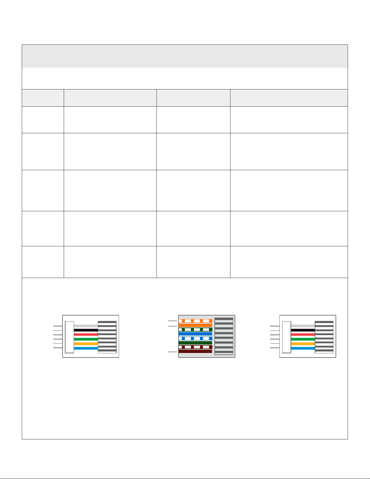
Refer to this table for your control options, pinouts and connections.
DCT RJ11 Pinout B
Closed
Stop
N/A
Ground
N/A
Open
DCT RJ11 Pinout A
Closed
Stop
+5V DC
Ground
IR Out (+)
Open
SDN (485) connection
Data +(WHT/ ORG)
Data - (ORG)
Ground - (BRWN)
485 port
Upto 200' max. CAT 5e or better
Control Wiring
CONTROL WIRING
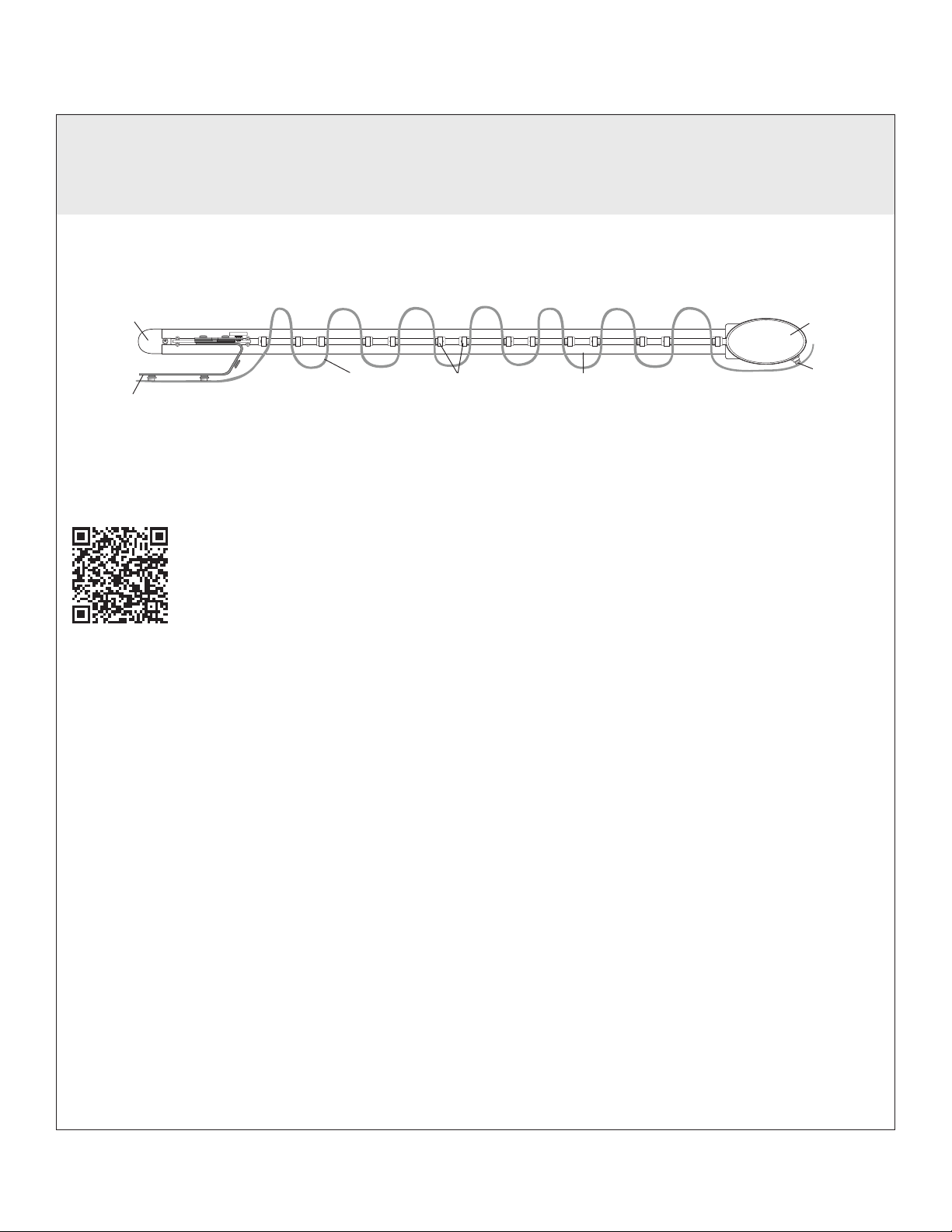
Glydea Ultra 35/60Irismo45Irismo35

9
Programming - RTS
Assign drapes to groups :
Next, program group controls. To pair with a permanent transmitter such as a multichannel Telis or
DecoFlex, follow these steps.
1. Press and hold the program button on the back of the installation remote until the drape jogs.
2. Select the channel where you want to create a group, then bump (do not hold down) the program
button on the back of the remote - the drape will jog.
3. Both remotes now control the drape.
4. Continue doing this with each drape until all drapes are programmed in the desired groups.
NOTE: Each RTS motor can be paired with 12 unique transmitters.
1. Download the TaHoma app.
2. Pair the grouped drapes with Link ProZ or TaHoma according to the instructions in the TaHoma app.
Pair Groups to control system (Link ProZ, TaHoma) :
hold the button until the
drape jogs
Installation
Remote
Permanent
Remote
Bump
(do not hold)
PROGRAMMING RTS

10
RS485 drapes can be programmed using the Screen Innovations SIFI via the web interface. This
programming can be done with a Windows or Mac computer either over LAN or wired directly to SIFI.
The following instructions are for a Windows computer, but the steps for programming on a Mac are very
similar. For a complete guide to program SIFI on a Mac, please visit our website. Before attempting to
program any motors with SIFI, verify that the rmware is up to date.
1. Launch Windows File Explorer
2. Click on the “Network” tab
3. Double click on the SIFI, the default web browser will launch
4. At the landing page, click the three lines in the top right corner, then click “Settings”
5. Select the “SDN” tab on the top left
6. Press the spyglass to auto discover motors on the 485 network (may have to press it more than once)
7. Click on the motor you want to program
8. Name the motor
Connect SIFI as shown below.
Data Pass-
through Input
Power/Data
Output
Bus Power
Supply
Data Hub
Device Device Device Device Device
SDN Wiring Pinout
Utilizing RJ-45 TIA-568B termination standard
Pin#
1
2
3
4
5
6
7
8
Color
Orange White
Orange
Green White
Blue
Blue White
Green
Brown White
Brown
Function
SDN RS485 (+)
SDN RS485 (-)
Reserved
Power 24v DC
Power 24v DC
Reserved
SDN RS485 Ground
SDN RS485 Ground
Pin 1
Pin 8
Stub length must not exceed 200’
SIFI
To IP Network/PC
Standard CAT - 5e
or higher cable
SDN / Power
c
c
c
c
c
PROGRAMMING 485
Programming - 485
SIFI
To IP Network
Standard CAT - 5e
or higher cable
SDN / Power c
c
012

11
PROGRAMMING ZIGBEE
STEP 2 - Assign drapes to groups:
All grouping of devices is completed within the TaHoma application:
1. Open the TaHoma application and navigate to the conguration tab.
2. Press the + symbol in the upper right corner.
3. Choose the Zigbee device type.
4. Select “Add Zigbee Group”.
5. Label the group.
6. Select the devices you would like to be included in this group.
STEP 3 - Pair devices or groups with a remote:
All pairing of devices and groups to remotes is completed within the TaHoma application. In
order to pair more than one shade to a channel, a group must be created rst.
1. Open the TaHoma application and navigate to the conguration tab.
2. Press the chain/link button next to the remote being congured.
3. Select the shade or group to pair from the list and deselect any other devices.
4. Quick press the programming button on the back of the remote and click OK in the application
to conrm.
NOTE: Each Zigbee Situo remote channel will be capable of pairing to a group containing up to 20 motors.
PROGRAMMING STEPS
(TaHoma/LinkPro Z must be plugged in and on the network)
1. Step 1: Pair each drape with TaHoma app.
2. Step 2: Assign drapes to groups and remotes.
3. Step 3: Pair devices and groups with remotes.
STEP 1 - Pair each drape with TaHoma app:
1. In the TaHoma app, press Add a device.
2. Select Zigbee, if this is 1st motor on the system, read the note and press “OK I understand”.
3. Scan the QR code, located on the Zigbee card, installed in the bottom of the motor.
4. Once the gateway identites the motor, name it by tapping “undened”, entering the name and
pressing OK to save the name.
5. Review the information related to the device and press “Next step”.
6. Verify if the name of the motor is correct and then press “Finish”.
Programming - RTS

12
For RTS
TROUBLESHOOTING 485 & RTS
Troubleshooting - 485
For 485
Problem Possible Cause Action to Take
Drapes won’t
operate.
Motor is not powered.
Please check AC connection, verify motor is plugged .
Incorrect or poor cable
termination.
Check the wire pinouts and termination. Look for broken, loose,
or damaged wires. Reterminate if necessary.
SIFI is not powered. To verify the si. is powered look for a green LED flashing on the
board, this light will either be steady on or flashing. If no light
is visible make sure power is available via the PoE injector or
check the power of your PoE switch.
SIFI is not on the local
network.
Use the service keypad (if available) to validate the 485 network
and motors are operating properly before troubleshooting SI.FI
network problems. Check that the SIFI is communicating on
the local network. Ping the device via the windows command
prompt, or make sure the device shows up in the network tab of
the Windows File Explorer.
Remote button presses
are too short.
When operating an RTS remote hold the buttons down for at
least 2 seconds.
The remote is being
used out of range.
Move within 30ft. of the shade. If the issue persists, adjust the
antenna to a new position, and make sure the antenna does not
touch metal.
The remote battery is
out of place or drained.
Check that the red LED on the remote flashes when buttons
are pressed. On the installation remote, pry off the back by
hand and ensure the battery is fully seated in the battery tray.
If the remote remains unresponsive, replace the battery with a
CR2430 3V lithium cell.
Tech Support: 512.832.6939

13
TROUBLESHOOTING ZIGBEE Tech Support: 512.832.6939
For Zigbee
Problem Possible Cause Action to Take
TaHoma LED is Red. No internet
connectivity.
Check network connection to the internet, and ensure the
TaHoma is properly connected via ethernet.
TaHoma LED if OFF. No power. Check if the USB dongle is properly seated into TaHoma.
Check the USB is connected to the included power supply
and that the AC is on.
Technical Support: 512.832.6939 s c re en i n n o v a t i o n s . c o m
Please use this QR Code
to access the updated
installation instructions
and related documents.
Troubleshooting - Zigbee

14
Low Voltage (24V DC) Lithium (12V DC)
Included controls Handheld Telis RTS remote Handheld Telis RTS remote
Optional handheld
controls
Telis Solaris RTS Pure
Decoflex wirefree tabletop
Telis 1/4 RTS Pure
Telis 1/4 RTS Patio
Telis 1/4 RTS Silver
Telis 1/4 RTS Lounge
Telis 16 RTS Pure/Silver
Veil IR Remote kit
Telis Solaris RTS Pure
Decoflex wirefree tabletop
Telis 1/4 RTS Pure
Telis 1/4 RTS Patio
Telis 1/4 RTS Silver
Telis 1/4 RTS Lounge
Telis 16 RTS Pure/Silver
Optional keypads Decoflex wirefree 1 - 5 channel
Smoove 1/4 RTS Pure
SDN Decoflex 8 button
Fontus keypad (with Fontus kits)
Decoflex wirefree 1 - 5 channel
Smoove 1/4 RTS Pure
Optional IP
controls
TaHoma
Link ProZ
Si-Fi (TRO.Y coming soon)
TaHoma
Link ProZ
Optional
infrastructure
Janus
Fontus
RTS Repeater
Connect
Somfy Data Hub
0 -10V interface
Smart Plug
Smart Light Switch
Smart Outlet
Smart Outdoor Plug
RTS Repeater
Connect
Note: The optional items above, may require additional RTS, 485 or Zigbee components to work
together. Consult SI Design Services for further assistance at 512.832.6939.
Irismo35
Glydea Ultra 35/60
Irismo45
CONTROL ACCESSORIES
Irismo45
Irismo35
Glydea Ultra 35/60
Control Accessories

Screen Innovations
9715-B Burnet Rd, Suite 400 Austin, TX 78758
512.832.6939
www.screeninnovations.com
400143 Ι v. 1.0 Ι 15 February 2021
Table of contents
Popular Garage Door Opener manuals by other brands

Security +
Security + LiftMaster Professional Security+ 3800 owner's manual

MyQ
MyQ LiftMaster 84504R user guide

Edison
Edison Autoslide installation manual

Wisniowski
Wisniowski INTRO 600 Assembly and operating instructions

Chamberlain
Chamberlain Security+ 3130M owner's manual

Chamberlain
Chamberlain WLED manual

MyQ
MyQ LiftMaster 84501 user guide

Aprimatic
Aprimatic S-MATIC AC500 Mechanical installation, Use and Maintenance instructions

Chamberlain
Chamberlain LM750EVGB Installation and operating instructions

Chamberlain
Chamberlain Power Drive Security+ PD752CDS owner's manual

Chamberlain
Chamberlain ATS 211 owner's manual

DTS
DTS 1000 installation manual